US9722698B2 - Channel performance monitoring and an optical communication system using same - Google Patents
Channel performance monitoring and an optical communication system using same Download PDFInfo
- Publication number
- US9722698B2 US9722698B2 US15/064,848 US201615064848A US9722698B2 US 9722698 B2 US9722698 B2 US 9722698B2 US 201615064848 A US201615064848 A US 201615064848A US 9722698 B2 US9722698 B2 US 9722698B2
- Authority
- US
- United States
- Prior art keywords
- optical
- optical channel
- performance parameter
- signal
- channel performance
- Prior art date
- Legal status (The legal status is an assumption and is not a legal conclusion. Google has not performed a legal analysis and makes no representation as to the accuracy of the status listed.)
- Active
Links
Images


Classifications
-
- H—ELECTRICITY
- H04—ELECTRIC COMMUNICATION TECHNIQUE
- H04B—TRANSMISSION
- H04B10/00—Transmission systems employing electromagnetic waves other than radio-waves, e.g. infrared, visible or ultraviolet light, or employing corpuscular radiation, e.g. quantum communication
- H04B10/07—Arrangements for monitoring or testing transmission systems; Arrangements for fault measurement of transmission systems
- H04B10/075—Arrangements for monitoring or testing transmission systems; Arrangements for fault measurement of transmission systems using an in-service signal
- H04B10/079—Arrangements for monitoring or testing transmission systems; Arrangements for fault measurement of transmission systems using an in-service signal using measurements of the data signal
- H04B10/0795—Performance monitoring; Measurement of transmission parameters
- H04B10/07953—Monitoring or measuring OSNR, BER or Q
-
- H—ELECTRICITY
- H04—ELECTRIC COMMUNICATION TECHNIQUE
- H04B—TRANSMISSION
- H04B10/00—Transmission systems employing electromagnetic waves other than radio-waves, e.g. infrared, visible or ultraviolet light, or employing corpuscular radiation, e.g. quantum communication
- H04B10/07—Arrangements for monitoring or testing transmission systems; Arrangements for fault measurement of transmission systems
- H04B10/075—Arrangements for monitoring or testing transmission systems; Arrangements for fault measurement of transmission systems using an in-service signal
- H04B10/079—Arrangements for monitoring or testing transmission systems; Arrangements for fault measurement of transmission systems using an in-service signal using measurements of the data signal
- H04B10/0795—Performance monitoring; Measurement of transmission parameters
-
- H—ELECTRICITY
- H04—ELECTRIC COMMUNICATION TECHNIQUE
- H04B—TRANSMISSION
- H04B10/00—Transmission systems employing electromagnetic waves other than radio-waves, e.g. infrared, visible or ultraviolet light, or employing corpuscular radiation, e.g. quantum communication
- H04B10/07—Arrangements for monitoring or testing transmission systems; Arrangements for fault measurement of transmission systems
- H04B10/075—Arrangements for monitoring or testing transmission systems; Arrangements for fault measurement of transmission systems using an in-service signal
- H04B10/079—Arrangements for monitoring or testing transmission systems; Arrangements for fault measurement of transmission systems using an in-service signal using measurements of the data signal
- H04B10/0793—Network aspects, e.g. central monitoring of transmission parameters
-
- H—ELECTRICITY
- H04—ELECTRIC COMMUNICATION TECHNIQUE
- H04B—TRANSMISSION
- H04B10/00—Transmission systems employing electromagnetic waves other than radio-waves, e.g. infrared, visible or ultraviolet light, or employing corpuscular radiation, e.g. quantum communication
- H04B10/07—Arrangements for monitoring or testing transmission systems; Arrangements for fault measurement of transmission systems
- H04B10/075—Arrangements for monitoring or testing transmission systems; Arrangements for fault measurement of transmission systems using an in-service signal
- H04B10/079—Arrangements for monitoring or testing transmission systems; Arrangements for fault measurement of transmission systems using an in-service signal using measurements of the data signal
- H04B10/0795—Performance monitoring; Measurement of transmission parameters
- H04B10/07951—Monitoring or measuring chromatic dispersion or PMD
-
- H—ELECTRICITY
- H04—ELECTRIC COMMUNICATION TECHNIQUE
- H04B—TRANSMISSION
- H04B10/00—Transmission systems employing electromagnetic waves other than radio-waves, e.g. infrared, visible or ultraviolet light, or employing corpuscular radiation, e.g. quantum communication
- H04B10/60—Receivers
-
- H—ELECTRICITY
- H04—ELECTRIC COMMUNICATION TECHNIQUE
- H04B—TRANSMISSION
- H04B10/00—Transmission systems employing electromagnetic waves other than radio-waves, e.g. infrared, visible or ultraviolet light, or employing corpuscular radiation, e.g. quantum communication
- H04B10/60—Receivers
- H04B10/61—Coherent receivers
- H04B10/616—Details of the electronic signal processing in coherent optical receivers
Definitions
- the present invention relates to a performance monitoring system and in particularly to a system and a method for digital performance monitoring in an optical communication system.
- CCM Channel Performance Monitoring
- CD Chromatic Dispersion
- PMD Polarization Mode Dispersion
- Current technologies enable compensation of up to +/ ⁇ 60 000 ps/nm accumulated CD and 30 ps of PMD. Consequently, the transmission reach is limited mainly by the Amplified Spontaneous Emission (“ASE”) noise generated by the optical amplifiers as well as the optical nonlinear effects.
- ASE Amplified Spontaneous Emission
- CPM is a requirement set in order to ensure satisfactory signal quality and to provide an in-traffic analysis of the “network health” for the Network Management System (“NMS”).
- NMS Network Management System
- CPM enables detecting, reporting and localizing potential failures at the transmission optical link.
- Exemplary performance parameters that a signal performance monitoring element may provide include (but are not limited to):
- US 20040213338 discloses a method to monitor the optical channel based on Analog to Digital Converter (“ADC”) samples before potential use of an equalizer.
- ADC Analog to Digital Converter
- the sampled data are conveyed to a DSP unit that may be located at the receiver card or at a remote location, in order to monitor at least one performance parameter of the channel.
- the publication describes the use of recovered decided data information following a FEC decoder block, in order to increase the signal monitoring capabilities by, for example, separating the histograms of “0” and “1” bits in order to calculate eye opening and signal noise histograms. Therefore, this disclosure relies on a priori knowledge of the characteristics of the specific Forward Error Correction (“FEC”) block that had been deployed, in order to provide channel performance parameters.
- FEC Forward Error Correction
- U.S. Pat. No. 8,824,902 describes methods for evaluating signal quality within the receiver along the path extending from the A/D convertor to the DSP or within the DSP, using an information extracting circuit, that is able to provide data for a determination means in order to detect Loss of Signal or signal deterioration, for example by analyzing histograms of the recovered constellation, with respect to a given threshold.
- this publication does not relate to the problem which the present invention faces, namely, that there are unknown proprietary techniques used to modulate/demodulate the optical channel.
- the recovered constellation is obtained in a non-agnostic way, by relying on known characteristics of the DSP blocks being used.
- the histogram analysis of the recovered constellation as described in this publication is not intended for estimating histograms of each constellation point separately, but instead, considers the constellation diagram histogram as a whole.
- US 20130236169 discloses dynamic performance monitoring systems and methods for optical networks to extract performance monitoring data in an optical networks based on the monitoring (via the use of a DSP device at the receiver) of existing channels or by using a probe channel with PRBS data before provisioning the service, in order to evaluate the optical path performances.
- the channel performance monitoring is carried out under real time traffic constraints. This disclosure pre-assumes that the network operator has a control/knowledge of the modulation techniques used for the channel and particularly for the probe channel, so that a known PRBS data stream may be relied upon.
- the DSP unit of a coherent receiver can provide information of the amount of CD, PMD and PDL that the optical signal has undergone.
- the ESNR level may also be estimated by comparing the recovered noisy symbols (after passing the DSP block stages before taking a decision) to the decided symbols (after decision has been taken and possible correction via the Forward Error Correction (“FEC”) decoder block was affected).
- FEC Forward Error Correction
- OSNR level of the signal is still not sufficient in order to monitor the overall OSNR system margin.
- Link induced physical degradations such as received optical power to the receiver, CD, PMD, PDL and more specifically nonlinear effects, might change significantly the OSNR level to be attained for a given BER target and therefore might cause difficulties in the estimation of the overall OSNR system margin.
- a method for OSNR system margin monitoring, robust to link impairments and based on the evaluation of the ESNR margin with a correction factor has been described in the Applicant's PCT application published under WO 2015132776.
- Optical coherent transceivers may be used to provide channel performance parameters derived from a real time DSP block at the receiver (referred to herein as in-line processing approach) that is primarily used to recover the transmitted data at the receiver side.
- in-line processing approach A conventional prior art method for inline processing CPM using DSP and FEC blocks of the coherent receiver is demonstrated in FIG. 1 , where the different channel performance monitors (for CD, PMD, PDL, OSNR, ESNR and OSNR margin) are derived from real time processing of the received channel signal, in order to recover the transmitted bit stream.
- the different channel performance monitors for CD, PMD, PDL, OSNR, ESNR and OSNR margin
- such an approach of relying on real time DSP may be appropriate at the link termination, and is not cost effective for channel performance monitoring purposes since in this case, recovery of real time transmitted data is not necessary.
- the cost of channel performance monitoring can therefore be reduced by the relaxing the requirement of in-line DSP block and using instead offline processing (at a lower processing rate than the channel symbol rate) of all or some of the DSP function blocks. This cost reduction allows deploying channel performance monitoring elements in strategic optical network nodes in order to get an in-traffic analysis of the “network health”.
- the DSP based channel performance monitoring should be independent from the DSP and FEC implementation used by a particular coherent transceiver manufacturer, in order to comply with a large number of different transceiver manufacturers.
- the DSP and FEC techniques that are used by the respective transceiver manufacturer are proprietary information than are not disclosed to network system vendors and/or to network operators.
- Information on the differential encoding mapping might not be disclosed to the network system vendor or network operator. If a pilot symbol approach is used to compensate the optical phase noise, information such as the pilot symbol word, overhead and period might not be known, making difficult to impossible for the network system vendor or for the operator to use a similar approach in order to extract channel performance parameters.
- Another example of unknown information might be the particular implementation of the FEC encoder and decoder, making very difficult for the network system vendor or operator to acquire the knowledge of the decided symbols after the FEC decoding for ESNR estimation without using the precise FEC algorithm.
- a partial knowledge could be for example one or more of the following:
- DSP and FEC blocks can be at least one of the following:
- the method provided by the present invention is applicable to all coherent modulation formats, for example, BPSK (Binary Phase shift Keying), M-ary PAM (Pulse Amplitude Modulation), QPSK (Quaternary Phase Shift Keying), M-ary QAM (Quadrature Amplitude Modulation), and the like.
- the method is also applicable for cases of dual polarization versions of the above modulation formats, with both single carrier (Orthogonal Frequency Division multiplexing) OFDM approaches.
- this method may also be applied to non-coherent modulation formats such as On-Off Keying (OOK), non-coherent M-PAM, Differential Phase Shift Keying (DPSK), Differential Quadrature Phase Shift Keying (DQPSK) and the like, since non-coherent modulation formats can also be detected while using a coherent receiver.
- non-coherent modulation formats such as On-Off Keying (OOK), non-coherent M-PAM, Differential Phase Shift Keying (DPSK), Differential Quadrature Phase Shift Keying (DQPSK) and the like, since non-coherent modulation formats can also be detected while using a coherent receiver.
- OOK On-Off Keying
- DPSK Differential Phase Shift Keying
- DQPSK Differential Quadrature Phase Shift Keying
- an optical communication system comprising:
- an optical transmitter configured to transmit an optical signal along at least one optical channel
- an optical receiver configured to receive the optical signal conveyed along the at least one optical channel
- one or more convertors being in communication with the optical receiver and operative to convert a received signal into digitized samples thereof;
- a first Digital Signal Processing (DSP) device being in communication with one or more convertors, and configured for in-line real time processing of at least one of the digitized samples, wherein the in-line real time processing includes performing at least partial recovery of digitized samples;
- DSP Digital Signal Processing
- a memory configured to store the at least partially recovered digitized samples
- a second DSP device being in communication with the optical receiver and/or with the memory and configured for offline processing of digitized samples of the optical signal and/or of the partially recovered stored samples;
- offline processing includes:
- the at least one optical channel performance parameter is estimated without a prior knowledge of information on a modulation format associated with the optical channel.
- a prior knowledge of information on a modulation format associated with the optical channel should be understood to denote information that relates to the type of modulation format, the implemented optical channel's symbol rate, the particular implementation of the modulation format at the transmitter (such as differential encoding, pilot symbols method, FEC encoding, etc.) as well as the particular implementation of the DSP chain at the optical receiver.
- the solution provided by the present invention enables the recovery of the noisy modulation constellation diagram related to the optical channel while using a blind DSP approach (i.e. without being aware of any information that relates to which bits or symbols were used while conveying the optical signal).
- a blind DSP approach is agnostic to the real application of the DSP and FEC blocks as implemented by the specific transceiver manufacturer at both sides, at the optical transmitter as well as at the optical receiver.
- the at least partial recovery of digitized samples is performed by the first DSP device without a prior knowledge of information on a modulation format associated with the optical channel.
- the at least one optical channel performance parameter which is either Electrical Signal-to-Noise Ratio (ESNR) and/or preFEC Bit Error Rate (BER) and a respective estimation thereof, is estimated (e.g. after having recovered the noisy constellation in a blind way) without a prior knowledge of information (i.e. without a prior knowledge obtained before carrying out the recovery of noisy constellation diagram and without a posterior knowledge) that relates to which symbols were used while conveying the optical signal.
- ESNR Electrical Signal-to-Noise Ratio
- BER Bit Error Rate
- the at least one optical channel performance parameter is either Electrical Signal-to-Noise Ratio (ESNR) and/or preFEC Bit Error Rate (BER), and a respective estimation of the performance parameter is carried out in a blind way (i.e. without being aware of any information that relates to which bits or symbols were used while conveying the optical signal).
- ESNR Electrical Signal-to-Noise Ratio
- BER Bit Error Rate
- the first DSP device is further operative to compensate for at least one impairment of an optical channel along which the optical signal has been conveyed.
- the first DSP device is further operative to estimate a value of at least one optical channel performance parameter characterizing the at least one optical channel, following the compensation provided for the at least one impairment of the optical channel.
- the first DSP device is installed at the optical receiver and the second DSP device is located separately therefrom (e.g. at a different electronic card of the same chassis).
- the first DSP device is installed at the optical receiver and the second DSP device is installed at a geographically remote location.
- the at least one optical channel performance parameter characterizing the at least one optical channel is a member of the group that consists of: modulation format, symbols rate, spectral shaping, and any combination thereof.
- the at least one optical channel performance parameter includes one or more of the following: Optical Signal to Noise Ratio (OSNR), Electrical Signal-to-Noise Ratio (ESNR), OSNR system margin, ESNR system margin, overall link impairment strength, Accumulated Chromatic Dispersion (ACD), Polarization Mode Dispersion (PMD), Polarization Dependent Loss (PDL), preFEC Bit Error Rate (BER).
- OSNR Optical Signal to Noise Ratio
- ESNR Electrical Signal-to-Noise Ratio
- OSNR system margin OSNR system margin
- overall link impairment strength Accumulated Chromatic Dispersion (ACD), Polarization Mode Dispersion (PMD), Polarization Dependent Loss (PDL), preFEC Bit Error Rate (BER).
- ACD Accumulated Chromatic Dispersion
- PMD Polarization Mode Dispersion
- PDL Polarization Dependent Loss
- BER preFEC Bit Error Rate
- a method for carrying out channel performance monitoring in an optical communication system comprising:
- the at least one optical channel performance parameter is estimated without a prior knowledge of information on a modulation format associated with the optical channel.
- the at least one optical channel performance parameter is either Electrical Signal-to-Noise Ratio (ESNR) and/or preFEC Bit Error Rate (BER) and a respective estimation thereof is carried out without any knowledge of information that relates to which symbols were used while conveying the optical signal.
- ESNR Electrical Signal-to-Noise Ratio
- BER Bit Error Rate
- the at least one optical channel performance parameter is either Electrical Signal-to-Noise Ratio (ESNR) and/or preFEC Bit Error Rate (BER) and a respective estimation thereof is carried out without any knowledge of information that relates to which bits were used while conveying the optical signal.
- ESNR Electrical Signal-to-Noise Ratio
- BER Bit Error Rate
- the method further comprises a step of compensating the optical signal for at least one impairment of an optical channel along which the optical signal has been conveyed.
- the method further comprises a step of estimating a value of at least one optical channel performance parameter characterizing the at least one optical channel following the compensation provided to the optical signal for the at least one impairment of the optical channel.
- the method further comprising:
- the at least one optical channel performance parameter includes one or more of the following: Optical Signal to Noise Ratio (OSNR), Electrical Signal-to-Noise Ratio (ESNR), OSNR system margin, ESNR system margin, overall link impairment strength, Accumulated Chromatic Dispersion (ACD), Polarization Mode Dispersion (PMD), Polarization Dependent Loss (PDL), preFEC Bit Error Rate (BER).
- OSNR Optical Signal to Noise Ratio
- ESNR Electrical Signal-to-Noise Ratio
- OSNR system margin OSNR system margin
- overall link impairment strength Accumulated Chromatic Dispersion (ACD), Polarization Mode Dispersion (PMD), Polarization Dependent Loss (PDL), preFEC Bit Error Rate (BER).
- ACD Accumulated Chromatic Dispersion
- PMD Polarization Mode Dispersion
- PDL Polarization Dependent Loss
- BER preFEC Bit Error Rate
- an apparatus configured to enable off-line digital performance monitoring, which comprises a digital signal processing (DSP) device configured to:
- DSP digital signal processing
- the at least one optical channel performance parameter is estimated without a prior knowledge of information on a modulation format associated with the optical channel.
- the at least one optical channel performance parameter is either Electrical Signal-to-Noise Ratio (ESNR) and/or preFEC Bit Error Rate (BER) and a respective estimation thereof is carried out without any knowledge of information that relates to which symbols were used while conveying the optical signal.
- ESNR Electrical Signal-to-Noise Ratio
- BER Bit Error Rate
- the at least one optical channel performance parameter is either Electrical Signal-to-Noise Ratio (ESNR) and/or preFEC Bit Error Rate (BER) and a respective estimation thereof is carried out without any knowledge of information that relates to which bits were used while conveying the optical signal.
- ESNR Electrical Signal-to-Noise Ratio
- BER Bit Error Rate
- the stored samples are at least partially recovered by another DSP device configured for carrying out an in-line processing.
- the at least one optical channel performance parameter includes one or more of the following: Optical Signal to Noise Ratio (OSNR Electrical Signal-to-Noise Ratio (ESNR), OSNR system margin, ESNR system margin, overall link impairment strength, Accumulated Chromatic Dispersion (ACD), Polarization Mode Dispersion (PMD), Polarization Dependent Loss (PDL), preFEC Bit Error Rate (BER).
- OSNR Electrical Signal-to-Noise Ratio ESNR
- OSNR system margin OSNR system margin
- ESNR system margin overall link impairment strength
- Accumulated Chromatic Dispersion ACD
- PMD Polarization Mode Dispersion
- PDL Polarization Dependent Loss
- BER bit Error Rate
- FIG. 1 illustrates a prior art CPM system that comprises a coherent receiver with inline DSP and FEC decoder blocks;
- FIG. 2 illustrates a schematic implementation of an embodiment of the present disclosure by which a CPM system comprises a coherent optical receiver front end followed by ADC blocks, a memory unit and an offline DSP block, for estimating channel performance parameters;
- FIG. 3 illustrates schematically an embodiment of the present disclosure of a DSP block and channel performance parameter estimation
- FIG. 4 exemplifies steps required according to an embodiment of the disclosure, to estimate the ESNR and the BER, based on a blind recovered constellation diagram analysis
- FIGS. 5A to 5D illustrate exemplary estimation results of ESNR and BER for a DP-QPSK signal using the blind recovered constellation diagram analysis
- FIG. 6 illustrates schematically another embodiment of the present disclosure of the DSP block and channel performance parameter estimation, in case that the modulation format of the channel is unknown;
- FIG. 7 illustrates schematically yet another embodiment of the present disclosure of the DSP block and channel performance parameter estimation, in case that the symbol rate of the channel is unknown;
- FIG. 8 illustrates schematically still another embodiment of the present disclosure of the DSP block and channel performance parameter estimation, in case that the symbol rate and the modulation format of the channel are unknown;
- FIG. 9 illustrates a schematic implementation of another embodiment of the present disclosure by which a CPM system comprises a coherent optical receiver front end followed by ADC blocks, an inline DSP block, a memory unit and an offline DSP block. Both inline and offline DSP blocks, providing the estimation of the channel performance parameters;
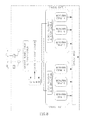
- FIG. 10 demonstrates a schematic implementation of another embodiment of the present disclosure by which a CPM system comprises two distinct units: a first unit, comprising a coherent optical receiver front end followed by ADC blocks, a memory unit and a data connectivity transmitter configured to send the stored signal samples towards a second remote unit that comprises a data connectivity receiver and an offline DSP block, for providing an estimation of the channel performance parameters; and
- FIG. 11 illustrates a schematic implementation of another embodiment of the present disclosure wherein a CPM system comprises two distinct units: a first unit, comprising a coherent optical receiver front end followed by ADC blocks, an inline DSP block, a memory unit and a data connectivity transmitter configured to send the stored signal samples towards a second remote unit that comprises a data connectivity receiver and an offline DSP block. Both inline and offline DSP blocks are used for providing an estimation of the channel performance parameters.
- the term “comprising” is intended to have an open-ended meaning so that when a first element is stated as comprising a second element, the first element may also include one or more other elements that are not necessarily identified or described herein, or recited in the claims.
- numerous specific details are set forth in order to provide a thorough understanding of the present invention. It should be apparent, however, that the present invention may be practiced without these specific details.
- FIG. 1 illustrates a prior art set-up of a CPM that relies on the use of the receiver part of a coherent transceiver which includes a coherent optical front end with an inline DSP and inline FEC decoder blocks, that provide the channel parameter estimations recovered under real time transmission of data.
- the optical signal After being conveyed along the optical network link, the optical signal arrives at its termination point and is forwarded to the coherent receiver.
- the optical signal Before the coherent detection, the optical signal may be optionally filtered using an optical filter (colored detection) or it can be detected without passing through an optical filter (colorless detection). In the latter case, all the optical signals conveyed via the channels present along the fiber, are forwarded to the optical receiver. Colorless detection is not harmful since it is the correct selection of the local oscillator (“LO”) frequency that determines which channel is coherently detected.
- LO local oscillator
- the signal is digitalized, using four high speed Analog to Digital converters (“ADCs”), and sent to a DSP device (block) in order to compensate for fiber impairments such as accumulated CD, polarization crosstalks, PMD, PDL, and the like.
- ADCs Analog to Digital converters
- DSP device block
- the impairment compensation algorithms may also provide the channel performance parameter such as accumulated CD, the PMD, PDL and OSNR levels. After applying these impairment compensation algorithms, the noisy symbols are recovered and symbol and bit decisions are performed using hard or soft detection techniques.
- the ESNR is estimated by measuring the average symbol power to average symbol noise power ratio.
- the symbol noise power is obtained by comparing the noisy symbol before the hard or soft decision and the decided symbol resulting from the output of the FEC decoder.
- the FEC decoder block has the ability to provide the pre FEC BER estimation. Based on the OSNR and ESNR parameters, the OSNR system margin and the overall impairment link impairment level can be estimated by using the method and systems such as those disclosed in the Applicant's PCT application, published under WO 2015132776.
- FIG. 2 illustrates a schematic view of an embodiment of the present disclosure of a CPM technique based on an offline processing of some stored samples of the detected optical signal.
- a portion of the signal conveyed along the optical channel is tapped off and forwarded to the coherent optical receiver front end.
- Optical to electrical conversion of the channel's signal can be done either in a colored or colorless manner.
- the detected signals from the four port outputs of the optical balanced receiver are then amplified and digitalized using four high speed ADCs.
- the ADCs do not necessarily operate in a continuous mode. They may be activated by a control signal, for example, upon requesting a channel performance monitoring by the network management system.
- the sampling rate of the ADC is set according to the symbol rate of the channel to be monitored. It can be chosen as greater or equal to the Nyquist sampling rate (known as twice the symbol rate), or as a sub-Nyquist rate.
- the sampled data are then stored in a memory unit when a control signal enables carrying out a writing process into the memory block.
- the size of the stored data will depend on the number of symbols to be recovered, to enable the channel performance parameter estimations and the quantization level of the ADCs. For example, in case of a sampling rate of 60 Gsamples/s with a 8 bit quantizer, in order to store 100,000 symbols arriving at baud rate of 30 Gbaud, it will be required to have a memory size of at least 400 MByte.
- Another control signal will then load the saved samples into the offline DSP block that estimates the channel performance parameters by recovering the noisy constellation diagram of the saved samples. It should be noted that since the processing is carried out in an offline mode, the processing rate may be much lower than the channel symbol rate. In addition, no FEC decoder is required in the CPM process in order to extract channel performance parameters such as ESNR and pre FEC BER. The resulting estimated parameters may be conveyed to a network management element for analyzing the channel quality and/or for taking other/further actions if needed.
- the DSP based channel performance monitoring should be independent from the DSP and FEC implementation used by a particular coherent transceiver manufacturer, in order for these implementations to comply with a large number of transceivers manufactured by different manufacturers, as in many cases, the DSP and FEC techniques used by the transceiver manufacturers are proprietary information that would not be disclosed to network system vendors or network operators.
- a differential encoding technique at the transmitter side with an appropriate carrier phase estimation and compensation technique at the receiver side (for example the Viterbi & Viterbi algorithm).
- Information on the differential encoding mapping might not be disclosed to the network system vendor or network operator. If a pilot symbol approach is applied in order to compensate the optical phase noise, information such as the pilot symbol word, overhead and period might be unknown, making difficult for the network system vendor or operator to implement a similar approach in order to extract channel performance parameters.
- non-disclosed information might be the particular implementation of the FEC encoder and decoder, making very difficult for the network system vendor or operator to have knowledge of the decided symbols after FEC decoding for ESNR estimation.
- FIG. 3 illustrates a schematic view of a DSP block configured to be used in an embodiment of the present disclosure of a CPM system.
- the DSP block enables recovering the noisy constellation diagram of the channel being monitored in a blind way (i.e. without the need to use known training sequence, pilot symbols or decided symbols at the receiver).
- a blind way i.e. without the need to use known training sequence, pilot symbols or decided symbols at the receiver.
- the Constant Modulus Algorithm (“CMA”) for QPSK modulation format or Multiple Modulus Algorithm (“MMA”) for QAM modulation formats and blind carrier recovery procedures to compensate the frequency offset and phase noise for example the Blind Phase Search, the Viterbi and Viterbi algorithm for QPSK modulation format and its derivation for QAM modulation formats.
- the blind impairment compensation algorithms also provide the channel performance parameters such as accumulated CD, the PMD, PDL and OSNR, ESNR, OSNR margin and the link impairment strength levels.
- all link impairment strength level used herein throughout the specification and claims, should be understood as the accumulated link impairment level that has not been compensated by the DSP, such as nonlinear impairments, channel crosstalks, channel spectral narrowing, residual uncompensated CD, residual uncompensated PMD, residual uncompensated PDL, etc. After applying these impairment compensation algorithms, the noisy symbols are recovered. It should be noted that since no FEC decoder block is required for implementing the CPM technique, the estimation of the ESNR level and the preFEC BER is done via a blind analysis of the modulation constellation diagram without requiring the knowledge of the decided symbols or bits after the FEC decoder.
- FIG. 4 illustrates schematically a flow chart that comprises the different steps required to estimate the ESNR and the BER, based on the blind recovered constellation diagram analysis.
- the noise power is evaluated by estimating the individual probability distribution function (“pdf”) of each noisy symbol of the constellation diagram (for example in the case of DP-QPSK modulation format, we have to estimate four pdfs of the four possible symbols of the modulation format at each polarization tributary).
- PDF probability distribution function
- the recovered noisy symbol pdfs can be estimated using statistical methods based on the knowledge of the noisy recovered constellation diagram (at both orthogonal polarization tributaries, if polarization multiplexing is used) obtained after passing the channel detected samples through the DSP block chain.
- Such a statistical method may for example be the Expectation and Maximization algorithm, applied to a mixture of multidimensional fit distribution functions.
- the basic fit distribution functions can be for example, Gaussian, Rayleigh, Ricean, Chi-Square or Lorentzian.
- the fitting pdf functions may be selected arbitrary or in an optimized way based on obtained recovered noisy constellation diagrams and assumptions relating to transmission link limitations (such as amplified spontaneous noise, nonlinear effects, optical phase noise, channel crosstalks).
- the multi-dimensional pdf of the overall recovered constellation diagram, p ⁇ right arrow over (r) ⁇ x ( ⁇ right arrow over (r) ⁇ ) ⁇ p ⁇ right arrow over (r) ⁇ x (r 1 , r 2 , . . . , r n ) is obtained from the multi-dimensional histograms of the recovered noisy diagram constellation.
- pdf of the symbol ⁇ right arrow over (S) ⁇ i [S i, 1 , S i,2 , . . .
- p x ( ⁇ right arrow over (S) ⁇ i ) is the probability of sending the symbol ⁇ right arrow over (S) ⁇ i on polarization x.
- N d,i the optimized number of basic distribution functions
- the statistical method that estimates p ⁇ right arrow over (r) ⁇ x ( ⁇ right arrow over (r) ⁇ / ⁇ right arrow over (S) ⁇ i ) for each symbol ⁇ right arrow over (S) ⁇ i at polarization tributary x, provides the full characteristics of p x ( ⁇ right arrow over (r) ⁇ / ⁇ right arrow over (S) ⁇ i ) and weights ⁇ tilde over (w) ⁇ i,j,x .
- the statistical method provides for each fit pdf f ⁇ right arrow over (r) ⁇ x ( ⁇ right arrow over (r) ⁇ / ⁇ right arrow over (S) ⁇ i ,j), the mean vector, the covariance matrix and the weight ⁇ tilde over (w) ⁇ i,j,x .
- the SER x,y at polarization x or y is given by:
- the pre FEC BER x/y is derived from the SER x/y according to known information about the symbol mapping concept used and not necessarily the exact symbol mapping itself. For example, when differential encoding is used to overcome the cycle slip problems after carrier phase recovery, it is known that the used symbol mapping should present some of bits invariance in the symbol word when proceeding to a constant degree rotation. When non-differential encoding is used, a Gray symbol mapping may be used.
- the ESNR x/y for polarization x or y is estimated as follows:
- ⁇ right arrow over ( ⁇ S) ⁇ i ⁇ 2 is the average symbol energy
- ⁇ right arrow over (e) ⁇ x/y ⁇ 2 is the average error vector energy
- N i,x/y ⁇ right arrow over (r) ⁇ right arrow over (S) ⁇ i ⁇ 2 is the average square distance of the recovered noisy symbols from the symbol ⁇ right arrow over (S) ⁇ i , assuming that ⁇ right arrow over (S) ⁇ i is sent on the x or y polarization.
- N i,x/y is estimated using p x ( ⁇ right
- p r k x (r k / ⁇ right arrow over (S) ⁇ i ) is the marginal pdf of p ⁇ right arrow over (r) ⁇ x ( ⁇ right arrow over (r) ⁇ / ⁇ right arrow over (S) ⁇ i ).
- the average SER, pre FEC BER and ESNR are obtained by averaging the calculated values of SER x/y , pre FEC BER x/y and ESNR x/y respectively, over the two polarization tributaries.
- FIGS. 5A to 5D illustrate exemplary estimation results of the ESNR and BER for a 120 Gb/s DP-QPSK channel using the blind recovered constellation recovering technique and blind constellation diagram analysis. It is assumed that the 120 G/s DP-QPSK channel is differential encoded and propagates over 100 km of standard single mode fiber.
- FIG. 5A represents the recovered noisy constellation diagram (on the polarization x tributary) of the channel after passing through the different stages of blind digital signal processing clocks to compensate the CD, polarization rotation, PMD, PDL frequency offset and carrier phase noise. 16384 noisy symbols are represented in the constellation diagram. Because of the detected optical noise and the soft differential decoding performed at the receiver, the noisy symbol distributions present correlated non-isotropic characteristics.
- Estimations for the preFEC BER and ESNR based on recovered noisy constellation diagram and Expectation and Maximization algorithm with bivariate Gaussian distributions as fit pdf, are presented in the following table, where the fit pdf function number per symbol, N d , varies from 1 to 3:
- FIGS. 5B, 5C and 5D demonstrate the isocontour levels of estimated pdfs over the original noisy constellation diagram when the fit pdf function number per symbol, N d , varies from 1 to 3, respectively. It can be seen that 1 fit function per symbol is not good enough to estimate correctly the preFEC BER, while the ESNR estimated is already satisfying. In this example, it requires 3 fit functions per symbol to reach satisfactory preFEC BER estimations.
- FIG. 6 illustrates schematically another embodiment of the present disclosure of the DSP block and channel performance parameter estimation, in a case where the modulation format of the channel is unknown. It is assumed that the channel modulation format can be selected from a set of known modulation formats, yet the currently applied modulation format is unknown.
- the signal samples may pass through blind DSP algorithms that are independent of the modulation format used. Data deskew, IQ imbalance, resampling, Coarse CD compensation and clock recovery, as well as an interpolation stage that may for example be carried out without the knowledge of the specific modulation format associated with the channel being monitored. Some blind algorithms may require the knowledge of the given modulation format.
- the CMA algorithm is fit for QPSK while the MMA algorithm with three radius is fit for rectangular 16-QAM.
- the sampled symbols are then sent to a bank of constellation dependent blind DSP sub-blocks, each being optimized for one of the modulation formats belonging to the modulation formats' set, that is suitable for the channel.
- FIG. 6 presents an exemplary embodiment in the case of selecting two possible modulation formats, but as will be appreciated by those skilled in the art, it may be further extended to a larger number of modulation formats by adding other constellation dependent blind DSP sub-blocks to the DSP bank.
- Channel performance parameter estimations such as OSNR, ESNR, preFEc BER, OSNR margin, overall link impairment are then derived for each sub-block.
- the sub-block that will provide the best recovered constellation diagram will be selected, and the estimated channel performance parameter derived from the selected sub-block will be selected.
- One possible criterion that can be used to select the best recovered constellation diagram is for example the estimated ESNR level.
- the information on the channel modulation format can be provided to the network management system.
- FIG. 7 illustrates schematically another embodiment of the present disclosure of the DSP block and channel performance parameter estimation, in a case where the symbol rate of the modulation format of the channel is unknown. It is assumed that the symbol rate of the channel modulation format can be selected from a set of known symbol rates but the currently used one for that channel modulation format is unknown.
- the signal samples may pass through blind DSP algorithms that are independent of the symbol rate of the channel. Data deskew, IQ imbalance, Coarse CD compensation for example, can be done without information on the specific symbol rate of the modulation format of the channel to be monitored.
- the resampling stage can be set to the one optimized to the maximum possible symbol rate. Some blind algorithms may require the information of the symbol rate.
- FIG. 7 demonstrates an exemplary embodiment in case of selecting two possible symbol rates, but as will be appreciated by those skilled in the art, it can be further extended to a large number of symbol rates by adding other symbol rate dependent blind DSP sub-blocks to the DSP bank.
- Channel performance parameter estimations such as OSNR, ESNR, preFEc BER, OSNR margin and overall link impairment, are then derived for each sub-block.
- the sub-block that provides the best recovered constellation diagram will be the selected one, and the estimated channel performance parameter derived from this sub-block, will be the selected one.
- One criterion to select the best recovered constellation diagram can be for example the estimated ESNR level.
- the information on the channel symbol rate can be provided to a network management element.
- FIG. 8 illustrates schematically yet another embodiment of the present disclosure of the DSP block and channel performance parameter estimation, in case neither the modulation format nor the symbol rate are known. It is assumed that the symbol rate and the modulation format of the channel can be selected from among a set of known symbol rates and modulation formats but the current ones used for the modulation format are unknown. In such a case, the signal samples may pass through blind DSP algorithms that are independent of the symbol rate and modulation format of the channel. Data deskew, IQ imbalance, Coarse CD compensation for example can be done without the information of the specific symbol rate and modulation format associated with the channel being monitored. The resampling stage can be set to the one optimized to the maximum possible symbol rate.
- the sampled symbols are then sent to a bank of symbol rate dependent blind DSP sub-block, each being optimized for one of the symbol rate belonging to the symbol rate set that are possible for the channel.
- symbol rate dependent sub-block there are modulation format dependent blind DSP sub-block with provides the estimated channel performance parameters according to a given symbol rate and modulation format.
- FIG. 8 demonstrates an exemplary embodiment in a case of selecting two possible symbol rates and three possible modulation formats for each symbol rate.
- this example may be further extended to a larger number of symbol rates and modulation formats, by adding other symbol rate dependent blind DSP sub-blocks to the DSP bank and modulation format dependent blind DSP sub-blocks in each symbol rate dependent blind DSP sub-block.
- Channel performance parameter estimations such as OSNR, ESNR, preFEc BER, OSNR margin, overall link impairment are then derived for each sub-block.
- the sub-block that provides the best recovered constellation diagram will be the selected one, and the estimated channel performance parameter of derived from this sub-block will be the one that will be used.
- One possible criterion for selecting the best recovered constellation diagram can be for example the estimated ESNR level.
- the information on the channel symbol rate and modulation format may be provided to the network management element/system.
- FIG. 9 is a schematic illustration of still another embodiment of the present disclosure of the CPM technique based on a combination of inline DSP and offline processing of some stored samples of the detected optical signal.
- the digitalized sampled are first sent to an inline DSP block that performs some tasks of the symbol constellation recovery process under real time conditions.
- This task can be related to the compensation of some impairments due to non-ideal detection processes, such as deskew, IQ imbalance, clock recovery and interpolation.
- the inline DSP block may also be used to compensate some of the link impairments such as accumulated CD, polarization recovery, PMD and PDL compensation. This compensation process will also enable estimating the related channel parameter performances.
- the partially recovered signal samples are stored at the memory block when the appropriate write control signal is provided to the memory block. Another control signal will then cause loading of the saved sampled to the offline DSP block that performs the compensation of the remaining impairments and estimates the remaining channel performance parameters by recovering the noisy constellation diagram of the saved samples. Once again, since the processing is carried out in an offline mode, the processing rate used, may be much lower than the channel symbol rate.
- the resulting estimated parameters may be sent to the network management system/element for analyzing the channel quality and/or for taking further actions if required.
- FIG. 10 is a schematic illustration of another embodiment of the present disclosure of the channel performance monitoring technique, where the channel performance monitor is divided into two distinct parts.
- the signals conveyed along the channel being monitored are forwarded to the coherent optical receiver front end.
- Optical to electrical conversion of the channel's signals may be carried out by using a colored or colorless method.
- the detected signals from the four port outputs of the optical balanced receiver are then amplified and digitalized using four high speed ADCs.
- the ADCs do not necessarily operate in a continuous mode. They may be activated by a control signal, for example while a channel performance monitoring is requested by the network management system.
- the signal samples are then stored at a memory unit when a control signal enables a writing process for storing these samples at the memory block.
- Another control signal will then cause loading the signal samples to a data connectivity transmitter that will allow forwarding the saved signal samples to the second part of the channel performance monitor.
- the second part of the channel performance monitor may be located at a different location. It may be another card connected to the chassis of the same network element platform. In such a case, the communication between the two cards can be done by implementing a backplane transmission protocol.
- the second part of the CPM can be located at a geographically remote location, e.g. at another network node, in order to perform a centralized processing of several optical network channels being monitored. In the latter case, the communication between the two CPM parts can be done by implementing a network communication protocol, for example via the Optical Supervisory Channel (“OSC”).
- OSC Optical Supervisory Channel
- the second part of the CPM consists of a data connectivity receiver that receives the signal samples sent by the first part of the CPM. These received signal samples are loaded to the offline DSP block that estimates the channel performance parameters by recovering the noisy constellation diagram of the saved samples
- FIG. 11 is a schematic illustration of another embodiment of the present disclosure of the channel performance monitoring technique where the channel performance monitor is divided into two distinct parts.
- the signals conveyed along a monitored channel are forwarded to a coherent optical receiver front end.
- Optical to electrical conversion of the channel's signals can be done in a colored or colorless manner.
- the detected signals from the four port outputs of the optical balanced receiver are then amplified and digitalized using four high speed ADCs, which do not necessarily operate in a continuous mode. They may be activated by a control signal, for example when a channel performance monitoring is requested by the network management system.
- the digitalized samples are first conveyed to an inline DSP block that executes some of the tasks involved with the symbol constellation recovery process under real time conditions.
- the inline DSP block can also be used to compensate some of the link impairments such as accumulated CD, polarization recovery, PMD and PDL compensation.
- This compensation process will also enable estimating the related channel parameter performances.
- the partially recovered signal samples are stored at the memory block upon receiving the appropriate write control signal at the memory block.
- Another control signal will then be used to initiate loading of the partially processed signal samples to a data connectivity transmitter that will enable forwarding the signal samples to the second part of the channel performance monitor.
- the second part of the channel performance monitor is located at a different location. This different location may be another card connected to the same chassis of the network element platform.
- the communication between the two cards can be done by implementing a backplane transmission protocol.
- the second part of the CPM can be located at a geographically remote location, such as another network node, in order to perform a centralized processing of several optical network channels being monitored.
- the communication between the two CPM parts can be done by implementing a network communication protocol, for example via the Optical Supervisory Channel (“OSC”).
- OSC Optical Supervisory Channel
- the second part of the CPM consists of a data connectivity receiver that receives the signal samples forwarded by the first part of the CPM. These received partially processed signal samples are loaded to the offline DSP block that performs the compensation of the remaining impairments and estimates the remaining channel performance parameters by recovering the noisy constellation diagram of the saved samples.
- the processing rate can be substantially lower than the channel symbol rate.
- the resulting estimated parameters can be forwarded to the network management system/element for analysis the channel quality and take further actions if needed.
- each of the verbs, “comprise” “include” and “have”, and conjugates thereof, are used to indicate that the object or objects of the verb are not necessarily a complete listing of members, components, elements or parts of the subject or subjects of the verb.
Landscapes
- Physics & Mathematics (AREA)
- Electromagnetism (AREA)
- Engineering & Computer Science (AREA)
- Computer Networks & Wireless Communication (AREA)
- Signal Processing (AREA)
- Optical Communication System (AREA)
Abstract
Description
-
- 1. Accumulated Chromatic Dispersion;
- 2. Polarization Mode Dispersion;
- 3. Polarization Dependent Loss (“PDL”);
- 4. Linear Crosstalk;
- 5. Nonlinear Crosstalk;
- 6. Optical Signal to noise Ratio (“OSNR”);
- 7. Electrical Signal to Noise Ratio (“ESNR”);
- 8. Optical Signal to noise Ratio Margin;
- 9. Electrical Signal to Noise Ratio Margin;
- 10. Overall link impairment strength;
- 11. Symbol Error Rate (“SER”); and
- 12. Bit Error Rate (“BER”).
-
- 1. Channel Modulation format or a set of possible modulation formats;
- 2. Channel symbol rate or a set of possible symbol rates; and
- 3. Channel spectral shaping or a set of possible spectral shaping.
-
- 1. The channel symbols are differential or non-differential encoded; and
- 2. Performance specifications of the transceivers' manufacturers, relating to the compensation of different link impairment via the DSP and FEC modules.
-
- using received samples to determine information characterizing the at least one optical channel used for conveying the optical signal;
- using the determined information to estimate a value of at least one optical channel performance parameter characterizing the at least one optical channel; and
- forwarding the value of the at least one optical channel performance parameter to a network management element; and
-
- using the digitized samples to determine information characterizing the at least one optical channel used for conveying the optical signal;
- using the determined information to estimate a value of at least one optical channel performance parameter characterizing the at least one optical channel; and
- forwarding the value of the at least one optical channel performance parameter to a network management element; and
-
- access a memory to retrieve stored samples of an optical signal;
- use the retrieved samples to determine information characterizing the at least one optical channel used for conveying the optical signal;
- use the determined information to estimate a value of at least one optical channel performance parameter characterizing the at least one optical channel; and
- forward the value of the at least one optical channel performance parameter to a network management element; and
Where px({right arrow over (S)}i) is the probability of sending the symbol {right arrow over (S)}i on polarization x.
and f{right arrow over (r)} x({right arrow over (r)}/{right arrow over (S)}i,j) is the jth fit probability density function is used to characterize the pdf of {right arrow over (S)}i at the x polarization tributary. Therefore, we get another expression for the pdf of overall diagram constellation:
Where Px/y(error/{right arrow over (S)}i) is the conditional symbol error probability when the symbol {right arrow over (S)}i is sent on polarization x or y and Px/y(error/{right arrow over (S)}i) is given by:
With D{{right arrow over (S)}i} being the decision region for symbol {right arrow over (S )}i.
Where
Where pr
| TABLE 1 | ||
| |
||
| 1 | 2 | 3 | ||
| BER [×10−3] | 2.5 | 3.68 | 3.97 | ||
| ESNR [dB] | 9.26 | 9.24 | 9.24 | ||
Claims (19)
Priority Applications (1)
| Application Number | Priority Date | Filing Date | Title |
|---|---|---|---|
| US15/064,848 US9722698B2 (en) | 2015-03-09 | 2016-03-09 | Channel performance monitoring and an optical communication system using same |
Applications Claiming Priority (2)
| Application Number | Priority Date | Filing Date | Title |
|---|---|---|---|
| US201562129979P | 2015-03-09 | 2015-03-09 | |
| US15/064,848 US9722698B2 (en) | 2015-03-09 | 2016-03-09 | Channel performance monitoring and an optical communication system using same |
Publications (2)
| Publication Number | Publication Date |
|---|---|
| US20160269110A1 US20160269110A1 (en) | 2016-09-15 |
| US9722698B2 true US9722698B2 (en) | 2017-08-01 |
Family
ID=55859033
Family Applications (1)
| Application Number | Title | Priority Date | Filing Date |
|---|---|---|---|
| US15/064,848 Active US9722698B2 (en) | 2015-03-09 | 2016-03-09 | Channel performance monitoring and an optical communication system using same |
Country Status (3)
| Country | Link |
|---|---|
| US (1) | US9722698B2 (en) |
| GB (1) | GB2538141B (en) |
| RU (1) | RU2696560C2 (en) |
Cited By (4)
| Publication number | Priority date | Publication date | Assignee | Title |
|---|---|---|---|---|
| US20170104529A1 (en) * | 2015-10-12 | 2017-04-13 | Fujitsu Limited | Monitoring apparatus for optical signal to noise ratio, signal transmission apparatus and receiver |
| US20170302372A1 (en) * | 2016-04-19 | 2017-10-19 | Fujitsu Limited | Network control apparatus and transmission quality margin calculation method |
| EP4007187A4 (en) * | 2019-08-26 | 2022-08-17 | Mitsubishi Electric Corporation | RECEIVER |
| US11962345B2 (en) | 2022-01-21 | 2024-04-16 | Precision Optical Technologies, Inc. | Configurable dispersion compensation in a pluggable optical transceiver |
Families Citing this family (17)
| Publication number | Priority date | Publication date | Assignee | Title |
|---|---|---|---|---|
| JP6325738B2 (en) * | 2014-03-27 | 2018-05-16 | 華為技術有限公司Huawei Technologies Co.,Ltd. | Apparatus and method for monitoring optical performance parameters, and optical transmission system |
| US9871582B2 (en) * | 2015-12-04 | 2018-01-16 | Cienna Corporation | Optical channel telemetry |
| JP6885093B2 (en) * | 2017-02-16 | 2021-06-09 | 富士通株式会社 | Transmission line monitoring device and transmission line monitoring method |
| CN106992835B (en) * | 2017-04-28 | 2019-04-02 | 中山大学 | The construction method of mode division multiplexing optical fiber telecommunications system and the optical fiber telecommunications system of building |
| US10951345B2 (en) * | 2017-08-28 | 2021-03-16 | Mitsubishi Electric Corporation | Optical communication device |
| CN109802723B (en) * | 2017-11-16 | 2022-03-08 | 富士通株式会社 | Method, device, receiver and communication system for monitoring optical signal to noise ratio |
| US10554309B2 (en) * | 2018-01-18 | 2020-02-04 | Mitsubishi Electric Research Laboratories, Inc. | Pilot-aided carrier phase estimation for optical communications |
| CN108880692B (en) * | 2018-06-05 | 2020-08-04 | 西南交通大学 | Modulation format recognition and optical signal-to-noise ratio monitoring method for coherent optical communication system |
| CN110971295B (en) * | 2018-09-28 | 2023-01-17 | 富士通株式会社 | Fiber optic nonlinear noise monitoring device and optical receiver |
| US10812183B2 (en) * | 2019-02-15 | 2020-10-20 | Viavi Solutions Inc. | Mitigating polarization dependent loss (PDL) by transforming frequency components to a ball |
| US10763968B1 (en) * | 2019-03-01 | 2020-09-01 | Google Llc | Coherent/IM-DD dual operation optical transceiver |
| CN113364519B (en) * | 2021-06-09 | 2023-02-24 | 聊城大学 | A light performance monitoring method, device, electronic equipment and storage medium |
| CN113452439B (en) * | 2021-06-28 | 2022-07-01 | 聊城大学 | Key parameter joint monitoring method in elastic optical network |
| CN113783611A (en) * | 2021-07-29 | 2021-12-10 | 香港理工大学深圳研究院 | A channel monitoring method, demodulation method, device, equipment and storage medium |
| CN114584212B (en) * | 2022-04-15 | 2023-12-08 | 中国电子科技集团公司第三十四研究所 | A modulation format and optical signal-to-noise ratio monitoring method for feature similarity analysis |
| CN115529094B (en) * | 2022-09-16 | 2025-03-25 | 西安邮电大学 | A method for determining the optimal threshold value based on energy difference detection algorithm |
| US12476712B2 (en) * | 2023-09-08 | 2025-11-18 | Huawei Technologies Co., Ltd. | Method and device for monitoring generalized optical signal-to-noise ratio, coherent receiver and network apparatus |
Citations (1)
| Publication number | Priority date | Publication date | Assignee | Title |
|---|---|---|---|---|
| US20160212747A1 (en) * | 2015-01-19 | 2016-07-21 | Futurewei Technologies, Inc. | Frequency-Division Multiplexing (FDM) Using Soft Clipping (SC) |
Family Cites Families (10)
| Publication number | Priority date | Publication date | Assignee | Title |
|---|---|---|---|---|
| JP3075200B2 (en) * | 1996-12-10 | 2000-08-07 | 日本電気株式会社 | Signal light monitor and optical amplifier using the same |
| US7457538B2 (en) * | 2002-05-15 | 2008-11-25 | Nortel Networks Limited | Digital performance monitoring for an optical communications system |
| US7623790B2 (en) * | 2005-09-24 | 2009-11-24 | Alcatel-Lucent Usa Inc. | Signal identification method |
| RU2328077C1 (en) * | 2006-11-30 | 2008-06-27 | Федеральное Государственное Унитарное Предприятие "Государственный Рязанский Приборный Завод" | Bidirectional optical coupler |
| US9490894B2 (en) * | 2008-12-08 | 2016-11-08 | Ciena Corporation | Coherent probe and optical service channel systems and methods for optical networks |
| US8660426B2 (en) * | 2009-06-23 | 2014-02-25 | Eci Telecom Ltd. | Optical signal to noise ratio monitoring technique and system |
| EP2372332B1 (en) * | 2010-03-31 | 2017-09-06 | Alcatel Lucent | Method for determining a chromatic dispersion of an optical channel |
| JP5598172B2 (en) * | 2010-08-30 | 2014-10-01 | 富士通株式会社 | Optical receiver, optical reception method, and optical transmission system |
| US8971701B2 (en) * | 2012-05-01 | 2015-03-03 | The Johns Hopkins University | Cueing system for universal optical receiver |
| GB2539123B (en) * | 2014-03-03 | 2020-10-28 | Eci Telecom Ltd | OSNR margin monitoring for optical coherent signals |
-
2016
- 2016-03-01 RU RU2016107439A patent/RU2696560C2/en active
- 2016-03-04 GB GB1603797.0A patent/GB2538141B/en active Active
- 2016-03-09 US US15/064,848 patent/US9722698B2/en active Active
Patent Citations (1)
| Publication number | Priority date | Publication date | Assignee | Title |
|---|---|---|---|---|
| US20160212747A1 (en) * | 2015-01-19 | 2016-07-21 | Futurewei Technologies, Inc. | Frequency-Division Multiplexing (FDM) Using Soft Clipping (SC) |
Cited By (7)
| Publication number | Priority date | Publication date | Assignee | Title |
|---|---|---|---|---|
| US20170104529A1 (en) * | 2015-10-12 | 2017-04-13 | Fujitsu Limited | Monitoring apparatus for optical signal to noise ratio, signal transmission apparatus and receiver |
| US10263698B2 (en) * | 2015-10-12 | 2019-04-16 | Fujitsu Limited | Monitoring apparatus for optical signal to noise ratio, signal transmission apparatus and receiver |
| US20170302372A1 (en) * | 2016-04-19 | 2017-10-19 | Fujitsu Limited | Network control apparatus and transmission quality margin calculation method |
| US10177843B2 (en) * | 2016-04-19 | 2019-01-08 | Fujitsu Limited | Network control apparatus and transmission quality margin calculation method |
| EP4007187A4 (en) * | 2019-08-26 | 2022-08-17 | Mitsubishi Electric Corporation | RECEIVER |
| US11705969B2 (en) | 2019-08-26 | 2023-07-18 | Mitsubishi Electric Corporation | Receiver |
| US11962345B2 (en) | 2022-01-21 | 2024-04-16 | Precision Optical Technologies, Inc. | Configurable dispersion compensation in a pluggable optical transceiver |
Also Published As
| Publication number | Publication date |
|---|---|
| US20160269110A1 (en) | 2016-09-15 |
| GB201603797D0 (en) | 2016-04-20 |
| RU2016107439A (en) | 2017-09-06 |
| GB2538141B (en) | 2021-06-02 |
| RU2016107439A3 (en) | 2019-06-03 |
| GB2538141A (en) | 2016-11-09 |
| RU2696560C2 (en) | 2019-08-05 |
Similar Documents
| Publication | Publication Date | Title |
|---|---|---|
| US9722698B2 (en) | Channel performance monitoring and an optical communication system using same | |
| US10720991B2 (en) | OSNR margin monitoring for optical coherent signals | |
| CN102656824B (en) | Carrier phase estimator for non-linear impairment monitoring and mitigation in coherent optical systems | |
| EP2975787B1 (en) | Adaptive post digital filter and inter-symbol interference equalizer for optical communication | |
| AU2016385470B2 (en) | In-band optical interference mitigation for direct-detection optical communication systems | |
| EP3207674B1 (en) | Chromatic dispersion estimation for digital coherent optical receivers | |
| EP2858272B1 (en) | Non-linear distortion compensator, method of compensating non-linear distortion, and optical receiver | |
| US20220321232A1 (en) | Frequency domain equalization method, equalizer, optical receiver, and system | |
| EP3367594B1 (en) | Coherent light-receiving device | |
| EP4046294A1 (en) | Device for compensating imperfections at a coherent optical receiver | |
| CN108476090B (en) | Adaptive coding and equalization apparatus and method for system matching | |
| Le et al. | Single-ended coherent receiver | |
| Di Rosa et al. | Blind radius directed equalizer with likelihood-based selection for probabilistically shaped and high order QAM | |
| CN116389207A (en) | A Modulation Format Identification Method Based on Signal Amplitude Histogram | |
| Anazawa et al. | Automatic modulation-format selection with white-box transponders: Design and field trial | |
| Faruk | Monitoring of OSNR using statistical moments of equalized signal in 16-QAM coherent optical receivers | |
| JP6550018B2 (en) | Multicarrier optical receiver and optical transmission system | |
| Torres-Ferrera et al. | Multi-format 800–1600 Gb/s coherent transceiver for inter-data centre interconnects over SMF | |
| Eriksson et al. | Nonlinear mitigation using probabilistically shaped real-valued modulation formats | |
| Yue et al. | Performance prediction for coherent optical transponder using accurate model | |
| Costa et al. | Influence of local oscillator-to-signal power ratio on the gaussianity of CP-QPSK signal statistics | |
| Hauske et al. | State Based OSNR Estimation in Amplitude Sampling Receivers | |
| Zhu et al. | Moments-based OSNR monitoring for QPSK and QAM coherent optical systems | |
| Wei et al. | Simultaneous optical signal to noise ratio and symbol rate estimation with blind chromatic dispersion compensation for auxiliary amplitude modulation optical signals | |
| Li et al. | Design and Implementation of Blind Equalization Algorithm for Multiband CAP Modulation in High Speed and High Spectral Efficiency Optical Data Link |
Legal Events
| Date | Code | Title | Description |
|---|---|---|---|
| AS | Assignment |
Owner name: ECI TELECOM LTD., ISRAEL Free format text: ASSIGNMENT OF ASSIGNORS INTEREST;ASSIGNORS:DAHAN, DAVID JIMMY;MELAMED, AMITAY;REEL/FRAME:037931/0583 Effective date: 20160225 |
|
| STCF | Information on status: patent grant |
Free format text: PATENTED CASE |
|
| MAFP | Maintenance fee payment |
Free format text: PAYMENT OF MAINTENANCE FEE, 4TH YEAR, LARGE ENTITY (ORIGINAL EVENT CODE: M1551); ENTITY STATUS OF PATENT OWNER: LARGE ENTITY Year of fee payment: 4 |
|
| AS | Assignment |
Owner name: HPS INVESTMENT PARTNERS, LLC, AS ADMINISTRATIVE AGENT, NEW YORK Free format text: SHORT-FORM PATENTS SECURITY AGREEMENT;ASSIGNOR:ECI TELECOM LTD.;REEL/FRAME:068857/0275 Effective date: 20240904 |
|
| MAFP | Maintenance fee payment |
Free format text: PAYMENT OF MAINTENANCE FEE, 8TH YEAR, LARGE ENTITY (ORIGINAL EVENT CODE: M1552); ENTITY STATUS OF PATENT OWNER: LARGE ENTITY Year of fee payment: 8 |