US972017A - Ore-concentrator. - Google Patents
Ore-concentrator. Download PDFInfo
- Publication number
- US972017A US972017A US54107010A US1910541070A US972017A US 972017 A US972017 A US 972017A US 54107010 A US54107010 A US 54107010A US 1910541070 A US1910541070 A US 1910541070A US 972017 A US972017 A US 972017A
- Authority
- US
- United States
- Prior art keywords
- frame
- belt
- strips
- ore
- supporting
- Prior art date
- Legal status (The legal status is an assumption and is not a legal conclusion. Google has not performed a legal analysis and makes no representation as to the accuracy of the status listed.)
- Expired - Lifetime
Links
- 238000009408 flooring Methods 0.000 description 7
- 229910052500 inorganic mineral Inorganic materials 0.000 description 5
- 239000000463 material Substances 0.000 description 5
- 239000011707 mineral Substances 0.000 description 5
- XLYOFNOQVPJJNP-UHFFFAOYSA-N water Substances O XLYOFNOQVPJJNP-UHFFFAOYSA-N 0.000 description 3
- XEEYBQQBJWHFJM-UHFFFAOYSA-N Iron Chemical compound [Fe] XEEYBQQBJWHFJM-UHFFFAOYSA-N 0.000 description 2
- 238000010276 construction Methods 0.000 description 2
- 241000202943 Hernandia sonora Species 0.000 description 1
- HCHKCACWOHOZIP-UHFFFAOYSA-N Zinc Chemical compound [Zn] HCHKCACWOHOZIP-UHFFFAOYSA-N 0.000 description 1
- 238000006073 displacement reaction Methods 0.000 description 1
- 229910052742 iron Inorganic materials 0.000 description 1
- 230000014759 maintenance of location Effects 0.000 description 1
- 230000000284 resting effect Effects 0.000 description 1
- 230000035939 shock Effects 0.000 description 1
- 239000011701 zinc Substances 0.000 description 1
- 229910052725 zinc Inorganic materials 0.000 description 1
Images


Classifications
-
- B—PERFORMING OPERATIONS; TRANSPORTING
- B03—SEPARATION OF SOLID MATERIALS USING LIQUIDS OR USING PNEUMATIC TABLES OR JIGS; MAGNETIC OR ELECTROSTATIC SEPARATION OF SOLID MATERIALS FROM SOLID MATERIALS OR FLUIDS; SEPARATION BY HIGH-VOLTAGE ELECTRIC FIELDS
- B03B—SEPARATING SOLID MATERIALS USING LIQUIDS OR USING PNEUMATIC TABLES OR JIGS
- B03B5/00—Washing granular, powdered or lumpy materials; Wet separating
- B03B5/02—Washing granular, powdered or lumpy materials; Wet separating using shaken, pulsated or stirred beds as the principal means of separation
Definitions
- This invention relates to improvements in ore concentrators.
- the principal object of this invention is to provide means for separating and saving the very line mineral which floats in the concentrating water and is ordinarily carried away and lost in the tailings.
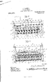
- Figure 1 is a side elevation of an ore concentrator embodying my improvements
- Fig. 2 is a central longitudinal section
- Fig. 3 is an end elevation
- Fig. 4 is a vertical transverse section taken on the line 4 4 of Fig'. l
- Fig. 5 is a horizontal section taken on the plane indicated by the dotted lines 5-5 of Fig. 4.
- the supporting frame comprises the bottom sills 1, top sills 2, vertical supports 3 and the cross pieces 4 and 5 for the bottom and top sills.
- the machine further comprises the usual oscillating agitator frame 6, which is suitably mounted for vibratory movement in the main frame and comprises the longitudinal or side pieces 7 the cross strips 8 extending between the side pieces and the rigid lflooring consisting of a longitudinal series of laterally spaced strips or boards 9, which are mounted upon the supporting strips 10, mounted upon the upper edges of the cross strips 8.
- the upper edges of the supporting strips 10 are inclined toward the discharge side of the machine to a suitable degree, say one-sixteenth of an inch to the foot.
- These supporting strips are held in position by retention screws 11 passing through the ends thereof at the discharge side of the machine and into the cross strips 8, and further by means of the dowel pins 12 carried by the cross pieces 8 and projecting into the supporting strips 10.
- the front ends of the supporting strips 1() may be held at different adjustments above the adjacent ends of the cross pieces 8 by the spacing blocks 13, and said supporting' strips are held in position after adjustment by the bolts and nuts 14 and 15, respectively, or other equivalent means.
- the flooring may be adjusted at different lateral inclinations, as may be found expedient in the concentration of the minerals.
- a pocket-forming belt 1G is mounted longitudinally in the main frame and passes over rollers 17 mounted at opposite ends of the oscillating' frame.
- This belt may be formed of alternate layers of rubber and canvas, or other like material, formed upon its face with a plurality of longitudinal iibs 17, which extend entirely around the belt and are spaced equi-distantly apart, formingpockets 18 for the reception of the mineral.
- the upper portion of this belt passes over the iiooring of the swinging frame, while the lower portion thereof passes around the drive roller 18, suitably mounted at one end of the main frame beneath the agitator frame, a tightening drum or roller 19 mounted in suitable brackets 20, and also over an idle roller 21 arranged intermediate of the ends of the main frame.
- the tightening roller 19 is for the purpose of holding the belt in iirm engagement with the roller 18, whereby the rotation of the latter will impart motion to the belt.
- the roller 18 may be turned at the proper speed by a worm and gear mechanism (not shown) for causing the belt to pass over the flooring of the agitator frame at the required speed.
- the agitator frame is intermittently moved in one direction by a cam 22 on the cam wheel 23, keyed to the transversevdrive shaft 24 provided with the cone pulley Q5, which may be connected by a belt with a second cone pulley overhead, whereby the drive shaft 24 will be rotated.
- the cam 22, at eac-h rotation of the cam wheel Q3, engages the cam block 25 adjustably mounted upon the bearing ⁇ plate 26.
- the bearing plate 26 is arranged upon the upper edge of the cross piece 27 which extends across the entire width of the agitator frame with its opposite ends bearing on the brackets Q8, which are mounted upon the side pieces T of the frame.
- the agitator frame is intermittently rocked in the opposite direction or returned into initial position by a resilient device which is shown in the present illustration as consisting of a flat resilient strip 29, attached to the horizontal supporting strip 30, mounted upon the top sills 2 of the main frame.
- the upper end of the strip 29 is connected by the link or rod 3l with a bearing bracket 32 suitably attached to one of the upper cross pieces 5.
- the lower end of the strip 29 is connected with the cross piece 27 by the rod 33, whereby the agitator frame is returned into initial position by the resilient strip 29.
- shock device which may be used to intermittently agitate the mineral on the upper portion of the belt each time the frame is returned to initial position.
- This device comprises a cross piece 34, which is mounted, by means of the bearings 35, upon one end of the agitator frame, and has attached to its inner face an inwardly curved resilient strip 3G, of suitable material.
- a rod 37 passes through a cross piece 38 extending between the standards 3 at the adjacent end of the main frame and also through the members 34 and 36. The inner end of this rod is provided with suitable cushioning means as 39, to modulate the jar induced in the agitator frame incident to the return of said frame to initial position.
- Bearing strips 40 are mounted upon the edges of the longitudinal brace bars 41 of the main frame and are provided with suitable guiding means, as 42, which engage opposite side edges of the belt and prevent any undue lateral movement or displacement thereof.
- Adjusting blocks 43 are countersunk in the adjustable ends of the supporting strips 10, whereby the adjacent side of the flooring or bed of the agitator frame and pocketforining belt may be raised to prevent the stock water or dressing water from splashing over that side of the belt.
- a tailing trough 44 is arranged at the discharge side of the frame to catch the overflow or tailings, said trough being connected by a tailing race 45 with the main race of the mill.
- the strip 46 at the extreme discharge edge of the flooring is suitably beveled upon its face or inclined to facilitate the passage of the tailings into the trough 44.
- the lead or high grade mineral will be caught in the pocket 47, while the second pocket 4S catches the second grade material or such material that passes over the pocket 47, while the pocket 49 catches the third grade material.
- the lead In treating a lead-iron-Zinc-ore, the lead will form in the first pocket, the iron in the second, and the Zinc in the third.
- a shaking frame consisting of side and cross pieces, adjustable supporting strips superimposed upon the cross pieces and extending under the first pocket of the belt at the feed side of the frame, a bed or flooring for the shaking frame consisting of a series of longitudinal spaced strips arranged on the supporting strips, spacing blocks insertible between the front ends of the supporting strips and the cross pieces for securing the required lateral slant to the floor, a flexible belt mounted in the main frame with its top portion passing over and resting upon the floor of the shaking frame, a plurality of continuous longitudinal ribs or riffles formed upon the exterior surface of the belt for dividing it into a number of laterally spaced pockets, and adjusting blocks in the front ends and upper edges of the supporting strips to ad-v just the strips of the flooring under the first pocket of the belt relative to the adjustment of the flooring as a whole.
Landscapes
- Crushing And Pulverization Processes (AREA)
Description
I. F. MONELL.
ORE CONGBNTRATOR.
APPLIoATIoN FILED JAN. a1, 1910.
Patented 0ct.4, 1910.
3 SHEETS-SHEET l.
MW mi QN A mi 1 L Il MM. 'wchJ FAU \\%M\ M. W W. WN MN 1 WN m @XML/wwwa Swag/,mago
I. F. MONELL.
ORE CONGENTRATOR.
APPLICATION :FILED 11111.31, 1910.
Patented 9013.4,1910
3 SHEETS-SHEET 3- after/umd;
nineN IRA F. MONELL, OF BOULDER, COLORADO.
ORE-CONCENTRATOR.
essere.
Specification of Letters Patent.
Patented Get. 4, 1910.
Application filed January 31, 1910. Serial No. 541,070.
To all whom it may concern.'
Be it known that I, IRA F. MONELL, a citizen of the United States, residing at Boulder, in the county of Boulder and State of Colorado, have invented certain new and useful Improvements in Ore-Concentrators; and I do declare the following to be a full, clear, and exact description of the invention, such as will enable others skilled in the art to which it appertains to make and use the same.
This invention relates to improvements in ore concentrators.
The principal object of this invention is to provide means for separating and saving the very line mineral which floats in the concentrating water and is ordinarily carried away and lost in the tailings. These objects I accomplish by means of the mechanism shown in the accompanying drawings, in which,
Figure 1 is a side elevation of an ore concentrator embodying my improvements; Fig. 2 is a central longitudinal section; Fig. 3 is an end elevation; Fig. 4 is a vertical transverse section taken on the line 4 4 of Fig'. l; Fig. 5 is a horizontal section taken on the plane indicated by the dotted lines 5-5 of Fig. 4.
Referring to the drawings, which are for illustrative purposes only, and are therefore not drawn to scale, the supporting frame comprises the bottom sills 1, top sills 2, vertical supports 3 and the cross pieces 4 and 5 for the bottom and top sills.
The machine further comprises the usual oscillating agitator frame 6, which is suitably mounted for vibratory movement in the main frame and comprises the longitudinal or side pieces 7 the cross strips 8 extending between the side pieces and the rigid lflooring consisting of a longitudinal series of laterally spaced strips or boards 9, which are mounted upon the supporting strips 10, mounted upon the upper edges of the cross strips 8. The upper edges of the supporting strips 10 are inclined toward the discharge side of the machine to a suitable degree, say one-sixteenth of an inch to the foot. These supporting strips are held in position by retention screws 11 passing through the ends thereof at the discharge side of the machine and into the cross strips 8, and further by means of the dowel pins 12 carried by the cross pieces 8 and projecting into the supporting strips 10. The front ends of the supporting strips 1() may be held at different adjustments above the adjacent ends of the cross pieces 8 by the spacing blocks 13, and said supporting' strips are held in position after adjustment by the bolts and nuts 14 and 15, respectively, or other equivalent means. By adjusting the front ends of the supporting' strips as above specified, it will be obvious that the flooring may be adjusted at different lateral inclinations, as may be found expedient in the concentration of the minerals.
A pocket-forming belt 1G is mounted longitudinally in the main frame and passes over rollers 17 mounted at opposite ends of the oscillating' frame. This belt may be formed of alternate layers of rubber and canvas, or other like material, formed upon its face with a plurality of longitudinal iibs 17, which extend entirely around the belt and are spaced equi-distantly apart, formingpockets 18 for the reception of the mineral. The upper portion of this belt passes over the iiooring of the swinging frame, while the lower portion thereof passes around the drive roller 18, suitably mounted at one end of the main frame beneath the agitator frame, a tightening drum or roller 19 mounted in suitable brackets 20, and also over an idle roller 21 arranged intermediate of the ends of the main frame. The tightening roller 19 is for the purpose of holding the belt in iirm engagement with the roller 18, whereby the rotation of the latter will impart motion to the belt. The roller 18 may be turned at the proper speed by a worm and gear mechanism (not shown) for causing the belt to pass over the flooring of the agitator frame at the required speed. The agitator frame is intermittently moved in one direction by a cam 22 on the cam wheel 23, keyed to the transversevdrive shaft 24 provided with the cone pulley Q5, which may be connected by a belt with a second cone pulley overhead, whereby the drive shaft 24 will be rotated. The cam 22, at eac-h rotation of the cam wheel Q3, engages the cam block 25 adjustably mounted upon the bearing` plate 26. The bearing plate 26 is arranged upon the upper edge of the cross piece 27 which extends across the entire width of the agitator frame with its opposite ends bearing on the brackets Q8, which are mounted upon the side pieces T of the frame. The agitator frame is intermittently rocked in the opposite direction or returned into initial position by a resilient device which is shown in the present illustration as consisting of a flat resilient strip 29, attached to the horizontal supporting strip 30, mounted upon the top sills 2 of the main frame. The upper end of the strip 29 is connected by the link or rod 3l with a bearing bracket 32 suitably attached to one of the upper cross pieces 5. The lower end of the strip 29 is connected with the cross piece 27 by the rod 33, whereby the agitator frame is returned into initial position by the resilient strip 29.
I will now describe a form of shock device which may be used to intermittently agitate the mineral on the upper portion of the belt each time the frame is returned to initial position. This device comprises a cross piece 34, which is mounted, by means of the bearings 35, upon one end of the agitator frame, and has attached to its inner face an inwardly curved resilient strip 3G, of suitable material. A rod 37 passes through a cross piece 38 extending between the standards 3 at the adjacent end of the main frame and also through the members 34 and 36. The inner end of this rod is provided with suitable cushioning means as 39, to modulate the jar induced in the agitator frame incident to the return of said frame to initial position. Bearing strips 40 are mounted upon the edges of the longitudinal brace bars 41 of the main frame and are provided with suitable guiding means, as 42, which engage opposite side edges of the belt and prevent any undue lateral movement or displacement thereof. Adjusting blocks 43 are countersunk in the adjustable ends of the supporting strips 10, whereby the adjacent side of the flooring or bed of the agitator frame and pocketforining belt may be raised to prevent the stock water or dressing water from splashing over that side of the belt. A tailing trough 44 is arranged at the discharge side of the frame to catch the overflow or tailings, said trough being connected by a tailing race 45 with the main race of the mill. The strip 46 at the extreme discharge edge of the flooring is suitably beveled upon its face or inclined to facilitate the passage of the tailings into the trough 44.
In practice, the lead or high grade mineral will be caught in the pocket 47, while the second pocket 4S catches the second grade material or such material that passes over the pocket 47, while the pocket 49 catches the third grade material. In treating a lead-iron-Zinc-ore, the lead will form in the first pocket, the iron in the second, and the Zinc in the third.
From the foregoing description taken in connection with the accompanying drawings, the construction and operation of the invention will be readily understood without requiring a more extended explanation.
Various changes in the form, proportion and the minor details of construction may be resorted to without departing from the principle or sacrificing any of the advantages of the invention, as defined in the appended claim.
lVhat is claimed as new is In an ore concentrator, a shaking frame consisting of side and cross pieces, adjustable supporting strips superimposed upon the cross pieces and extending under the first pocket of the belt at the feed side of the frame, a bed or flooring for the shaking frame consisting of a series of longitudinal spaced strips arranged on the supporting strips, spacing blocks insertible between the front ends of the supporting strips and the cross pieces for securing the required lateral slant to the floor, a flexible belt mounted in the main frame with its top portion passing over and resting upon the floor of the shaking frame, a plurality of continuous longitudinal ribs or riffles formed upon the exterior surface of the belt for dividing it into a number of laterally spaced pockets, and adjusting blocks in the front ends and upper edges of the supporting strips to ad-v just the strips of the flooring under the first pocket of the belt relative to the adjustment of the flooring as a whole.
In testimony whereof I have hereunto set my hand in presence of two subscribing witnesses.
IRA F. MONELL.
TWitnesses I?. IV. KoHLnR, L. HERMON.
Priority Applications (1)
| Application Number | Priority Date | Filing Date | Title |
|---|---|---|---|
| US54107010A US972017A (en) | 1910-01-31 | 1910-01-31 | Ore-concentrator. |
Applications Claiming Priority (1)
| Application Number | Priority Date | Filing Date | Title |
|---|---|---|---|
| US54107010A US972017A (en) | 1910-01-31 | 1910-01-31 | Ore-concentrator. |
Publications (1)
| Publication Number | Publication Date |
|---|---|
| US972017A true US972017A (en) | 1910-10-04 |
Family
ID=3040401
Family Applications (1)
| Application Number | Title | Priority Date | Filing Date |
|---|---|---|---|
| US54107010A Expired - Lifetime US972017A (en) | 1910-01-31 | 1910-01-31 | Ore-concentrator. |
Country Status (1)
| Country | Link |
|---|---|
| US (1) | US972017A (en) |
-
1910
- 1910-01-31 US US54107010A patent/US972017A/en not_active Expired - Lifetime
Similar Documents
| Publication | Publication Date | Title |
|---|---|---|
| US2314542A (en) | Apparatus for separating materials | |
| US682749A (en) | Ore-concentrator. | |
| US1033219A (en) | Endless-belt ore-concentrator. | |
| US1813303A (en) | Dry separator | |
| US970283A (en) | Concentrating-table. | |
| US898020A (en) | Separating-table. | |
| US1999000A (en) | Apparatus for the concentration and/or sizing of mineral particles | |
| US798385A (en) | Separating-machine. | |
| US744021A (en) | Concentrator for fine ores. | |
| US2103663A (en) | Means for concentrating minerals | |
| US490850A (en) | Ore-concentrator | |
| US964083A (en) | Ore-concentrator. | |
| US1605752A (en) | Concentrator or jigger | |
| US997843A (en) | Ore-concentrator. | |
| US1041842A (en) | Ore concentrator or slimer. | |
| US261177A (en) | Chaeles d | |
| US820234A (en) | Ore-slimer. | |
| US552519A (en) | Ore-concentrator | |
| US333322A (en) | monell | |
| US1060323A (en) | Apparatus for concentrating ore. | |
| US1685644A (en) | Ore-concentrating device | |
| US325429A (en) | Tereitoey | |
| US786799A (en) | Ore-concentrator. | |
| US2341662A (en) | Apparatus for separating loose masses | |
| US688567A (en) | Ore-concentrator. |