CROSS-REFERENCE TO RELATED APPLICATION
This application claims the benefit of Taiwan Patent Application No. 103103913, filed on Feb. 6, 2014, in the Taiwan Intellectual Property Office, the disclosure of which is incorporated herein in its entirety by reference.
BACKGROUND
Technical Field
The present invention relates to a light switching module for switching the state of the incident light to transparent state or opaque state according to the principle of light refraction.
Description of Related Art
With the developments of the smart glass and smart window, various applications of light adjusting device or light switching device are thereby on the increase. The technical principle of conventional electronically controlled liquid crystal type smart windows is to sandwich polymer-dispersed liquid crystals between two sheets of glass, and to control the alignment directions of the liquid crystals of ordered or disordered arrangement with electric field for adjusting the transmittance. The polymer-dispersed liquid crystals are liquid crystal droplets dispersed into a polymer matrix and aligned in a continuous power supply to maintain a transparent state; however, it usually has some problems of uneven dispersion of the liquid crystals, and power consumption under continuous power supply.
SUMMARY OF THE INVENTION
Accordingly, the present disclosure is to provide a novel, inventive and useful light switching module for switching the transmitting light to transparent state or opaque state.
An aspect of the present disclosure is to provide a light switching module comprising a first refractive element comprising a first substrate with a first refractive index comprising a plurality of first micro-lens structures on a side thereof; a first patterned retardation microstructure disposed on the plurality of first micro-lens structures; and a first birefringent layer disposed on the first patterned retardation microstructure for forming a first optical axis region with a first optical axis and a second optical axis region with a second optical axis; wherein the first optical axis region has an extraordinary refractive index in the direction parallel to the first optical axis and an ordinary refractive index in the direction perpendicular to the first optical axis; the second optical axis region has an extraordinary refractive index in the direction parallel to the second optical axis and an ordinary refractive index in the direction perpendicular to the second optical axis; wherein the first optical axis region and the second optical axis region are interleaved arrangement; the first optical axis and the second axis are perpendicular to each other; a second refractive element adjacent to a side of the first refractive element comprising a second substrate with a second refractive index comprising a plurality of second micro-lens structures on a side thereof; a second patterned retardation microstructure disposed on the plurality of second micro-lens structures; and a second birefringent layer disposed on the second patterned retardation microstructure for forming a third optical axis region with a third optical axis and a fourth optical axis region with a fourth optical axis; wherein the third optical axis region has an extraordinary refractive index in the direction parallel to the third optical axis and an ordinary refractive index in the direction perpendicular to the third optical axis; the fourth optical axis region has an extraordinary refractive index in the direction parallel to the fourth optical axis and an ordinary refractive index in the direction perpendicular to the fourth optical axis; wherein the third optical axis region and the fourth optical axis region are interleaved arrangement; the third optical axis and the fourth axis are perpendicular to each other; and a shifting means connected to the first refractive element or the second refractive element for adjusting the relative position of the first refractive element and the second refractive element; wherein the first refractive index of the first substrate is the same as one of the extraordinary refractive index and the ordinary refractive index of the first birefringent layer; the second refractive index of the second substrate is the same as one of the extraordinary refractive index and the ordinary refractive index of the second birefringent layer; one of the first optical axis and the second optical axis is parallel to one of the third optical axis and the fourth optical axis.
In a light switching module of a preferred embodiment of the present invention, the curvatures of the micro-lens of the first micro-lens structures of the first refractive element and the corresponding second micro-lens structures of the second refractive element are the same.
In a light switching module of another preferred embodiment of the present invention, each of the micro-lens of the first micro-lens structures and the second micro-lens structures is concave-lens or convex-lens.
In a light switching module of another preferred embodiment of the present invention, the plurality of first micro-lens structures and the plurality of second micro-lens structures are continuously or discontinuously arranged in one-dimension or two-dimension.
In a light switching module of another preferred embodiment of the present invention, wherein the areas of the first optical axis region and the second optical axis region of the first birefringent layer and the areas of the third optical axis region and the fourth optical axis region of the second birefringent layer are the same.
In a light switching module of another preferred embodiment of the present invention, when the directions of the first optical axis of the first optical axis region and the second optical axis of the second optical axis region and the directions of the respectively corresponding third optical axis of the third optical axis region and the fourth optical axis of the fourth optical axis region are all parallel to each other, the light switching module is in transparent state; when the directions of the first optical axis of the first optical axis region and the second optical axis of the second optical axis region and the directions of the respectively corresponding third optical axis of the third optical axis region and the fourth optical axis of the fourth optical axis region are all perpendicular to each other, the light switching module is in opaque state.
In a light switching module of another preferred embodiment of the present invention, the pitch of the first micro-lens structures is in a range of 0 μm to 1000 μm; the pitch of the second micro-lens structures is in a range of 0 μm to 1000 μm; the width of each of the first micro-lens structures is in a range of 10 μm to 1000 μm; the width of each of the second micro-lens structures is in a range of 10 μm to 1000 μm; the height of each of the first micro-lens structures is in a range of 10 μm to 1000 μm; the height of each of the second micro-lens structures is in a range of 10 μm to 1000 μm.
In a light switching module of another preferred embodiment of the present invention, the material of the birefringent layer is liquid crystal, birefringent crystal or birefringent resin.
BRIEF DESCRIPTION OF THE DRAWINGS
The accompanying drawings, which are incorporated herein and constitute part of this specification, illustrate example embodiments of the invention, and together with the general description given above and the detailed description given below, serve to explain the features of the invention.
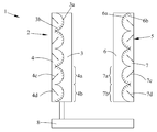
FIG. 1 is a perspective view of the light switching module of an aspect of the present invention;
FIG. 2-1 and FIG. 2-2 are perspective views illustrating the principle of transparent state and opaque state of the light switching module of an embodiment of the present invention;
FIG. 3 is a perspective view illustrating the first refractive element and the second refractive element of the light switching module of another embodiment of the present invention.
DESCRIPTION OF EMBODIMENTS OF THE INVENTION
To describe the technical features of the present invention in greater detail, preferred embodiments of the present invention are provided below along with the accompanied drawings accordingly as follows. The various embodiments will be described in detail with reference to the accompanying drawings. References made to particular examples and implementations are for illustrative purposes, and are not intended to limit the scope of the invention or the claims.
The light switching module of the present invention will be described along with the accompanied drawings accordingly as follows. It is appreciated that the same reference numbers will be used throughout the drawings to refer to the same or like parts.
Referring to FIG. 1, an aspect of the present disclosure is to provide a light switching module 1 comprising a first refractive element 2 comprising a first substrate 3 with a first refractive index comprising a plurality of first micro-lens structures 3 a on a side thereof; a first patterned retardation microstructure 3 b disposed on the plurality of first micro-lens structures 3 a; and a first birefringent layer 4 disposed on the first patterned retardation microstructure 3 b for forming a first optical axis region 4 a with a first optical axis 4 c and a second optical axis region 4 b with a second optical axis 4 d; wherein the first optical axis region 4 a has an extraordinary refractive index in the direction parallel to the first optical axis 4 c and an ordinary refractive index in the direction perpendicular to the first optical axis 4 c; the second optical axis region 4 b has an extraordinary refractive index in the direction parallel to the second optical axis 4 d and an ordinary refractive index in the direction perpendicular to the second optical axis 4 d; wherein the first optical axis region 4 a and the second optical axis region 4 b are interleaved arrangement; the first optical axis 4 c and the second axis 4 d are perpendicular to each other; a second refractive element 5 adjacent to a side of the first refractive element 2 comprising a second substrate 6 with a second refractive index comprising a plurality of second micro-lens structures 6 a on a side thereof; a second patterned retardation microstructure 6 b disposed on the plurality of second micro-lens structures 6 a; and a second birefringent layer 7 disposed on the second patterned retardation microstructure 6 b for forming a third optical axis region 7 a with a third optical axis 7 c and a fourth optical axis region 7 b with a fourth optical axis 7 d; wherein the third optical axis region 7 a has an extraordinary refractive index in the direction parallel to the third optical axis 7 c and an ordinary refractive index in the direction perpendicular to the third optical axis 7 c; the fourth optical axis region 7 b has an extraordinary refractive index in the direction parallel to the fourth optical axis 7 d and an ordinary refractive index in the direction perpendicular to the fourth optical axis 7 d; wherein the third optical axis region 7 a and the fourth optical axis region 7 b are interleaved arrangement; the third optical axis 7 c and the fourth optical axis 7 d are perpendicular to each other; and a shifting means 8 connected to the first refractive element 2 or the second refractive element 5 for adjusting the relative position of the first refractive element 2 and the second refractive element 5; wherein the first refractive index of the first substrate 3 is the same as one of the extraordinary refractive index and the ordinary refractive index of the first birefringent layer 4; the second refractive index of the second substrate 6 is the same as one of the extraordinary refractive index and the ordinary refractive index of the second birefringent layer 7; one of the first optical axis 4 c and the second optical axis 4 d is parallel to one of the third optical axis 7 c and the fourth optical axis 7 d.
In a light switching module of a preferred embodiment of the present invention, the absolute value of radius of curvature of the micro-lens of the first micro-lens structures of the first refractive element and the corresponding second micro-lens structures of the second refractive element are the same; therefore, each of the micro-lenses can be concave-lens or convex-lens of same curvature.
In a light switching module of another preferred embodiment of the present invention, the plurality of first micro-lens structures and the plurality of second micro-lens structures are continuously or discontinuously arranged in one-dimension or two-dimension for enhancing the effect and uniformity of the opaque state of the light switching module with incident light in different directions.
In a light switching module of another preferred embodiment of the present invention, wherein the areas of the first optical axis region and the second optical axis region of the first birefringent layer and the areas of the third optical axis region and the fourth optical axis region of the second birefringent layer are the same.
In a light switching module of another preferred embodiment of the present invention, as shown in
FIG. 2-1, the first
birefringent layer 41 has a first
optical axis region 41 a and a second
optical axis region 41 b in the presence of a first patterned retardation microstructure (not shown in the figure); the second
birefringent layer 71 has a third
optical axis region 71 a and a fourth
optical axis region 71 b in the presence of a second patterned retardation microstructure (not shown in the figure); the incident light can be considered as combined light of two directional component; in this schematic,
incident light component 10 a is perpendicular to the first
optical axis 41 c of the first
optical axis region 41 a of the first
birefringent layer 41;
incident light component 10 b is parallel to the first
optical axis 41 c of the first
optical axis region 41 a of the first
birefringent layer 41;
incident light component 11 a is perpendicular to the second
optical axis 41 d of the second
optical axis region 41 b of the first
birefringent layer 41;
incident light component 11 b is parallel to the second
optical axis 41 d of the second
optical axis region 41 b of the first
birefringent layer 41; in a condition of that the first refractive index of the
first substrate 31 and the ordinary refractive index of the first
birefringent layer 41 are the same, and the second refractive index of the
second substrate 61 and the ordinary refractive index of the second
birefringent layer 71 are the same, and the directions of the first
optical axis 41 c of the first
optical axis region 41 a and the directions of the corresponding third
optical axis 71 c of the third
optical axis region 71 a and the second
optical axis 41 d of the second
optical axis region 41 b and the corresponding fourth
optical axis 71 d of the fourth
optical axis region 71 b are respectively parallel to each other, the
incident component 10 a 11 a can induce the same ordinary refractive index of the first
birefringent layer 41 and the second
birefringent layer 71, and therefore, the substrate and the birefringent layer are the same media to the
incident light component 10 a 11 a, and do not occur refraction phenomenon at the interface; accordingly, the
incident light component 10 a 11 a can directly pass through the light switching module; as for the
incident light component 10 b 11 b, the
incident light component 10 b 11 b can induce the same extraordinary refractive index of the first
birefringent layer 41 and the second
birefringent layer 71, and therefore, the substrate and the birefringent layer are the different media to the
incident light component 10 b 11 b, and occur refraction phenomenon at the interface; however, the direction of the
incident light component 10 b 11 b can be adjusted to the original direction with the first
micro-lenses structures 31 a and the second
micro-lens structures 61 a of same curvature; accordingly, the light switching module is in transparent state.
As shown in
FIG. 2-2, the first
birefringent layer 42 has a first
optical axis region 42 a and a second
optical axis region 42 b in the presence of a first patterned retardation microstructure (not shown in the figure); the second
birefringent layer 72 has a third
optical axis region 72 a and a fourth
optical axis region 72 b in the presence of a second patterned retardation microstructure (not shown in the figure); the incident light can still be considered as combined light of two directional component; in this schematic,
incident light component 20 a is perpendicular to the first
optical axis 42 c of the first
optical axis region 42 a of the first
birefringent layer 42;
incident light component 20 b is parallel to the first
optical axis 42 c of the first
optical axis region 42 a of the first
birefringent layer 42;
incident light component 21 a is perpendicular to the second
optical axis 42 d of the second
optical axis region 42 b of the first
birefringent layer 42;
incident light component 21 b is parallel to the second
optical axis 42 d of the second
optical axis region 42 b of the first
birefringent layer 42; in a condition of that the first refractive index of the
first substrate 32 and the ordinary refractive index of the first
birefringent layer 42 are the same, and the second refractive index of the
second substrate 62 and the ordinary refractive index of the second
birefringent layer 72 are the same, and the directions of the first
optical axis 42 c of the first
optical axis region 42 a and the directions of the corresponding fourth
optical axis 72 d of the fourth
optical axis region 72 b and the second
optical axis 42 d of the second
optical axis region 42 b and the corresponding third
optical axis 72 c of the third
optical axis region 72 a are respectively perpendicular to each other, the
incident light component 20 a 21 a can induce the ordinary refractive index of the first
birefringent layer 42 and the extraordinary refractive index of the second
birefringent layer 72, and therefore, the
second substrate 62 and the second
birefringent layer 72 are the different media to the
incident light component 20 a 21 a, and occur refraction phenomenon at the interface; accordingly, the
incident light component 20 a 21 a cannot directly pass through the light switching module; as for the
incident light component 20 b 21 b, the
incident light component 20 b 21 b can induce the extraordinary refractive index of the first
birefringent layer 42 and the ordinary refractive index of the second
birefringent layer 72, and therefore, the
first substrate 32 and the first
birefringent layer 42 are the different media to the
incident light component 20 b 21 b, and occur refraction phenomenon at the interface, and cannot directly pass through the light switching module; accordingly, the light switching module is in opaque state.
Referring to FIG. 3, in a light switching module of another preferred embodiment of the present invention, the pitch S1 of the first micro-lens structures 33 a between the first substrate 33 and the first birefringent layer 43 is in a range of 0 μm to 1000 μm; the pitch S2 of the second micro-lens structures 63 a between the first substrate 63 and the first birefringent layer 73 is in a range of 0 μm to 1000 μm; the width W1 of each of the first micro-lens structures 33 a is in a range of 10 μm to 1000 μm; the width W2 of each of the second micro-lens structures 63 a is in a range of 10 μm to 1000 μm; the height H1 of each of the first micro-lens structures 33 a is in a range of 10 μm to 1000 μm; the height H2 of each of the second micro-lens structures 63 a is in a range of 10 μm to 1000 μm.
In a light switching module of another preferred embodiment of the present invention, the material of the birefringent layer is liquid crystal, birefringent crystal or birefringent resin.
The foregoing description of the exemplary embodiments of the invention has been presented only for the purposes of illustration and description and is not intended to be exhaustive or to limit the invention to the precise forms disclosed. Many modifications and variations are possible in light of the above teaching.
The embodiments were chosen and described in order to explain the principles of the invention and their practical application so as to activate others skilled in the art to utilize the invention and various embodiments and with various modifications as are suited to the particular use contemplated. Alternative embodiments will become apparent to those skilled in the art to which the present invention pertains without departing from its spirit and scope. Accordingly, the scope of the present invention is defined by the appended claims rather than the foregoing description and the exemplary embodiments described therein.