US9705205B2 - Bi-polarized broadband annular radiation unit and array antenna - Google Patents
Bi-polarized broadband annular radiation unit and array antenna Download PDFInfo
- Publication number
- US9705205B2 US9705205B2 US14/401,529 US201314401529A US9705205B2 US 9705205 B2 US9705205 B2 US 9705205B2 US 201314401529 A US201314401529 A US 201314401529A US 9705205 B2 US9705205 B2 US 9705205B2
- Authority
- US
- United States
- Prior art keywords
- unit
- dipoles
- balun
- arm
- arms
- Prior art date
- Legal status (The legal status is an assumption and is not a legal conclusion. Google has not performed a legal analysis and makes no representation as to the accuracy of the status listed.)
- Expired - Fee Related
Links
Images


Classifications
-
- H—ELECTRICITY
- H01—ELECTRIC ELEMENTS
- H01Q—ANTENNAS, i.e. RADIO AERIALS
- H01Q21/00—Antenna arrays or systems
- H01Q21/24—Combinations of antenna units polarised in different directions for transmitting or receiving circularly and elliptically polarised waves or waves linearly polarised in any direction
- H01Q21/26—Turnstile or like antennas comprising arrangements of three or more elongated elements disposed radially and symmetrically in a horizontal plane about a common centre
-
- H—ELECTRICITY
- H01—ELECTRIC ELEMENTS
- H01Q—ANTENNAS, i.e. RADIO AERIALS
- H01Q1/00—Details of, or arrangements associated with, antennas
- H01Q1/12—Supports; Mounting means
- H01Q1/22—Supports; Mounting means by structural association with other equipment or articles
- H01Q1/24—Supports; Mounting means by structural association with other equipment or articles with receiving set
- H01Q1/241—Supports; Mounting means by structural association with other equipment or articles with receiving set used in mobile communications, e.g. GSM
- H01Q1/246—Supports; Mounting means by structural association with other equipment or articles with receiving set used in mobile communications, e.g. GSM specially adapted for base stations
-
- H—ELECTRICITY
- H01—ELECTRIC ELEMENTS
- H01Q—ANTENNAS, i.e. RADIO AERIALS
- H01Q19/00—Combinations of primary active antenna elements and units with secondary devices, e.g. with quasi-optical devices, for giving the antenna a desired directional characteristic
- H01Q19/10—Combinations of primary active antenna elements and units with secondary devices, e.g. with quasi-optical devices, for giving the antenna a desired directional characteristic using reflecting surfaces
- H01Q19/108—Combination of a dipole with a plane reflecting surface
-
- H—ELECTRICITY
- H01—ELECTRIC ELEMENTS
- H01Q—ANTENNAS, i.e. RADIO AERIALS
- H01Q21/00—Antenna arrays or systems
- H01Q21/24—Combinations of antenna units polarised in different directions for transmitting or receiving circularly and elliptically polarised waves or waves linearly polarised in any direction
-
- H—ELECTRICITY
- H01—ELECTRIC ELEMENTS
- H01Q—ANTENNAS, i.e. RADIO AERIALS
- H01Q25/00—Antennas or antenna systems providing at least two radiating patterns
- H01Q25/001—Crossed polarisation dual antennas
-
- H—ELECTRICITY
- H01—ELECTRIC ELEMENTS
- H01Q—ANTENNAS, i.e. RADIO AERIALS
- H01Q21/00—Antenna arrays or systems
- H01Q21/06—Arrays of individually energised antenna units similarly polarised and spaced apart
- H01Q21/08—Arrays of individually energised antenna units similarly polarised and spaced apart the units being spaced along or adjacent to a rectilinear path
-
- H—ELECTRICITY
- H01—ELECTRIC ELEMENTS
- H01Q—ANTENNAS, i.e. RADIO AERIALS
- H01Q5/00—Arrangements for simultaneous operation of antennas on two or more different wavebands, e.g. dual-band or multi-band arrangements
- H01Q5/40—Imbricated or interleaved structures; Combined or electromagnetically coupled arrangements, e.g. comprising two or more non-connected fed radiating elements
- H01Q5/42—Imbricated or interleaved structures; Combined or electromagnetically coupled arrangements, e.g. comprising two or more non-connected fed radiating elements using two or more imbricated arrays
Definitions
- the invention relates to antennae used in mobile communications and more particularly, relates to a bi-polarized broadband annular radiation unit and a single frequency and dual frequency broadband array antennae incorporating the radiation unit.
- bi-polarized broadband annular radiation unit is mainly formed by casting of zinc alloy.
- Chinese Patent Application No.: CN101425626A filed by the present applicant Comba communication system (China) Ltd. and published on May 6, 2009 discloses bi-polarized broadband annular radiation unit. It includes the following parts: two pairs of orthogonally polarized dipoles for transmitting or receiving communication signals; and a balancer corresponding to each dipole for feeding power to the dipole in a balanced manner.
- Each dipole includes two unit arms symmetrically mounted on the respective balancer. Two arms are linearly symmetrical about the balancer. One end of each unit arm is secured onto the balancer, while the other end thereof is provided with a loading line extending vertically downwardly.
- One object of the invention is to overcome drawbacks aforementioned and provide a bi-polarized broadband annular radiation unit formed by sheet metal stamping which eliminates problems such as complex forming process, heavy weight and huge cost caused during course of forming a bi-polarized broadband annular radiation unit using casting method.
- Another object of the invention is to provide a broadband array antenna employing the above radiation unit.
- the bi-polarized broadband annular radiation unit of the instant invention is intended to be installed on a metal reflective plate thus constituting a communication antenna and defining an annular construction by two pairs of orthogonally polarized dipoles. It includes:
- each dipole comprising two symmetrical unit arms of a single line sheet shape, one end of a unit arm being facing to a corresponding end of the other unit arm, and a distal end of each unit arm of at least one pair of dipoles is provided with a loading line;
- each balun arm including two parallel balun lines, and the top ends of the two balun lines being connected with corresponding ends of the two unit arms of a corresponding dipole.
- Each unit arm and the balun line and/or loading line connected to the same unit arm are made by sheet metal stamping forming process or casting process.
- the respective balun arm are mounted onto a common base by bottom ends of their respective balun lines, and the entire radiation unit is integrally formed by sheet metal stamping process or casting process.
- the arrangement of the loading lines may be implemented by one of the following manners.
- All the dipoles are provided with loading lines, and adjacent loading lines of the adjacent dipoles are orthogonally arranged.
- the two loading lines of one of the two pairs of dipoles are all vertically downwardly orientated, while the other pair of the dipoles has their two loading lines all horizontally inwardly orientated; and adjacent loading lines of the adjacent dipoles are orthogonally arranged.
- the two loading lines of one of the two pairs of dipoles are all vertically downwardly orientated, while the other pair of the dipoles has their two loading lines all horizontally outardly orientated; and adjacent loading lines of the adjacent dipoles are orthogonally arranged.
- One of two unit arms of each pair of dipoles is provided with a vertically downwardly orientated loading line, while the other unit arm thereof is provided with a horizontally inwardly orientated loading line; and adjacent loading lines of the adjacent dipoles are arranged at a same direction.
- All the unit arms are provided with vertically downward or upward loading lines.
- All the unit arms are provided with downwardly or upwardly inclined loading lines.
- All the unit arms are provided with horizontally inward or outward loading lines.
- All the unit arms are provided with inwardly or outwardly inclined loading lines.
- each unit arm is equipped with an adjusting block of uniform shape for adjusting matching performance of the entire radiation unit.
- a plastic holding clip is placed between each unit arm of the respective dipoles and a corresponding balun arm for connection of the all vibrator arms with balun arms of the entire radiation unit, thus maintaining relative location between the vibrator arm and balun arm.
- this significantly enhances entire structural strength of the radiation unit and ensures uniformity of radiation units in batch production.
- a broadband array antenna includes a metal reflective plate operating as a reflector, wherein at least two radiation units as described above are linearly arranged on the metal reflective plate.
- the bi-polarized broadband annular radiation unit of the invention has simple structure and may be fabricated using aluminum by sheet metal stamping forming process or casting process and therefore it has good stability. Moreover, the weight of the product is further reduced such that uniformity is maintained for the product.
- the bi-polarized broadband annular radiation unit of the invention is made using sheet metal stamping forming process or casting process both of which are simple and inexpensive due to radiation unit of a single line sheet design.
- FIG. 1 shows a structural view of a first embodiment of a bi-polarized broadband annular radiation unit of the invention
- FIG. 2 shows an expanded view of a metal sheet of a first embodiment of a bi-polarized broadband annular radiation unit of the invention
- FIG. 3 shows structure of a first embodiment of a bi-polarized broadband annular radiation unit of the invention in which a plastic holding clip is used for holding purpose;
- FIG. 4 shows a structural view of a second embodiment of a bi-polarized broadband annular radiation unit of the invention
- FIG. 5 shows a structural view of a third embodiment of a bi-polarized broadband annular radiation unit of the invention
- FIG. 6 shows a structural view of a fourth embodiment of a bi-polarized broadband annular radiation unit of the invention.
- FIG. 7 shows a structural view of a fifth embodiment of a bi-polarized broadband annular radiation unit of the invention.
- FIG. 8 shows a structural view of a sixth embodiment of a bi-polarized broadband annular radiation unit of the invention.
- FIG. 9 shows a structural view of a seventh embodiment of a bi-polarized broadband annular radiation unit of the invention.
- FIG. 10 shows a structural view of an eighth embodiment of a bi-polarized broadband annular radiation unit of the invention.
- FIG. 11 shows a structural view of a ninth embodiment of a bi-polarized broadband annular radiation unit of the invention.
- FIG. 12 shows a structural view of a tenth embodiment of a bi-polarized broadband annular radiation unit of the invention
- FIG. 13 shows a structural view of an eleventh embodiment of a bi-polarized broadband annular radiation unit of the invention
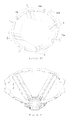
- FIGS. 14 and 15 respectively show structural views of a twelfth embodiment of a bi-polarized broadband annular radiation unit of the invention illustrating from different perspectives;
- FIG. 16 shows a perspective view of a single frequency broadband array antenna formed by the radiation units of the invention.
- FIG. 17 shows a perspective view of a dual frequency broadband array antenna formed by the radiation units of the invention.
- a radiation unit 100 includes two pairs of dipoles. Each pair of the dipoles includes two dipoles which are symmetrically and oppositely arranged. Each dipole is a vibrator unit and therefore, there are totally four vibrator units 1 , 2 , 3 , and 4 .
- the vibrator units 1 and 3 are symmetrical about each other, and vibrator units 2 and 4 are also symmetrical about each other, thus achieving assembling of the radiation unit in a polarization-orthogonal manner.
- each vibrator unit includes two unit arms one end of each unit arm is opposite to and separated from one end of the other unit arm.
- Each unit arm is of a single line sheet design.
- a distal end of each unit arm of the vibrator unit is provided with a loading line. The distal end of one unit arm is far away from a corresponding distal end of the other unit arm.
- the vibrator units 1 - 4 are held on balun arms 5 a , 5 b , 5 c , and 5 d respectively.
- the vibrator unit 1 includes two unit arms 11 a and 11 b .
- a loading line 12 a is disposed on the unit arm 11 a and a loading line 12 b is disposed on the unit arm 11 b .
- the two unit arms 11 a and 11 b are secured on the balun arm 5 b .
- the vibrator unit 2 includes two unit arms 21 a and 21 b .
- a loading line 22 a is disposed on the unit arm 21 a and a loading line 22 b is disposed on the unit arm 21 b .
- the two unit arms 21 a and 21 b are secured on the balun arm 5 b .
- the vibrator unit 3 includes two unit arms 31 a and 31 b .
- a loading line 32 a is disposed on the unit arm 31 a and a loading line 32 b is disposed on the unit arm 31 b .
- the two unit arms 31 a and 31 b are secured on the balun arm 5 c .
- the vibrator unit 4 includes two unit arms 41 a and 41 b .
- a loading line 42 a is disposed on the unit arm 41 a and a loading line 42 b is disposed on the unit arm 41 b .
- the two unit arms 41 a and 41 b are secured on the balun arm 5 d . Based on orthogonal polarization design, all the unit arms of the entire radiation unit are annularly and symmetrically distributed.
- a first pair of dipoles i.e., the vibrator units 1 and 3
- a second pair of dipoles i.e., the vibrator units 2 and 4
- the adjacent loading lines of the adjacent vibrator units are orthogonally arranged.
- the loading line 12 a is orthogonal to the loading line 42 b
- the loading line 12 b is orthogonal to the loading line 22 a
- the loading line 22 b is orthogonal to the loading line 32 a
- the loading line 32 b is orthogonal to the loading line 42 a
- the vibrator units 1 - 4 share a common base 6 .
- the loading lines of the adjacent vibrator units may be angled to each other for example the lines may be suitable inclined such as inwardly or outwardly.
- the orthogonal solution is the first consideration, vertical downward and horizontal inward configuration is employed.
- Each balun arm includes a pair of parallel balun lines 51 and 52 .
- a bottom end of each balun line is installed on the base 6 , while the other end thereof is connected to one end of a unit arm facing a corresponding end of the other unit arm.
- top ends of the two balun lines 51 and 52 are connected with the ends, which are facing to each other, of the two unit arms of the same vibrator units.
- all the balun arms are arranged on the base 6 and take the shape of horn.
- the entire radiation unit 100 including the vibrator units 1 - 4 , balun arms 5 a - 5 d , and base 6 are integrally formed of preferably aluminum by sheet metal stamping forming process.
- the radiation units 100 prepared by sheet metal stamping forming method, together with orthogonal design of the adjacent loading lines of adjacent vibrator units, might improve irrelevancy between two polarizations of the radiation unit 100 , enhance separation and radiation characteristics between two polarizations such as cross polarization resolution and the like.
- all its component including all vibrator arms and balun arms are suitable held in place by eight plastic holding clips 7 a , 7 b , 7 c , 7 d , 7 e , 7 f , 7 g , and 7 h , thus all the vibrator arms and balun arms of the radiation unit being formed as an entity, maintaining relative locations among these vibrator arms and balun arms, and dramatically improving structural strength of the radiation unit.
- FIG. 4 According to a second embodiment of a bi-polarized broadband annular radiation unit of the invention, the same construction as that disclosed in aforementioned embodiment is employed. There is also difference in this embodiment.
- a component consisted of a vibrator unit 1 and a corresponding balun arm (such as balun arm 5 a ), in other word, consisted of two unit arms (for example arms 11 a and 11 b ) of the same vibrator unit (such as unit 1 ) and two balun lines 51 and 52 of the same balun arm, is an integral and independent component, and it may be assembled together with a separate base.
- FIG. 5 According to a third embodiment of a bi-polarized broadband annular radiation unit of the invention, the same construction as that disclosed in aforementioned embodiments is employed. The difference lies in implementation of respective unit arm. All the unit arms of the entire radiation unit 100 (such as unit arms 11 a and 11 b ) each have an adjusting block 110 at a corresponding symmetrical location. In this embodiment, the adjusting block 110 is of a disk shape.
- FIG. 6 According to a fourth embodiment of a bi-polarized broadband annular radiation unit of the invention, the same base and balun arm are used as those disclosed in the first or second embodiment of the invention. The difference lies in implementation of the vibrator loading lines.
- the loading lines (such as those labeled 12 a and 12 b ) of a pair of dipoles 1 and 3 are vertically downwardly orientated, while the loading lines (such as those labeled 42 a and 42 b ) of another pair of dipoles 2 and 4 are horizontally outwardly orientated.
- the adjacent loading lines of the adjacent dipoles are still orthogonal to each other.
- FIG. 7 According to a fifth embodiment of a bi-polarized broadband annular radiation unit of the invention, the same base and balun arm are used as those disclosed in the first or second embodiment of the invention. The difference lies in implementation of the vibrator loading lines.
- the loading lines (such as those labeled 12 a and 12 b ) disposed two distal ends of the two unit arms (such as those labeled 11 a and 11 b ) respectively of each vibrator unit (for example one labeled 1 ) are asymmetrically arranged.
- the loading line 12 a on one unit arm 11 a is horizontally arranged
- the loading line 12 b on the another unit arm 11 b is vertically downwardly arranged.
- the adjacent loading lines of the adjacent dipoles are symmetrical and oriented in the same direction.
- FIG. 8 According to a sixth embodiment of a bi-polarized broadband annular radiation unit of the invention, the same construction as that of the fifth embodiment is employed and the difference lies in implementation of the unit arm.
- the entire unit arms (such as those labeled 11 a and 11 b ) of the entire radiation unit each have an adjusting block 110 at a corresponding symmetrical location.
- the adjusting block 110 is of a disk shape.
- FIG. 9 According to a seventh embodiment of a bi-polarized broadband annular radiation unit of the invention, the same base and balun arm are used as those disclosed in the first or second embodiment of the invention. The difference lies in implementation of the vibrator loading lines.
- all the loading lines (e.g. 12 a and 12 b ) of the unit arms (such as 11 a and 11 b ) are vertically downwardly arranged.
- FIG. 10 According to an eighth embodiment of a bi-polarized broadband annular radiation unit of the invention, the same construction is used as that of the seventh embodiment. The difference lies in implementation of the unit arms of the dipole.
- the entire unit arms (such as those labeled 11 a and 11 b ) of the entire radiation unit each have an adjusting block 110 at corresponding symmetrical locations.
- the adjusting block 110 is of a disk shape.
- FIG. 11 According to a ninth embodiment of a bi-polarized broadband annular radiation unit of the invention, the same base and balun arm are used as those disclosed in the first or second embodiment of the invention. The difference lies in implementation of the loading lines.
- the loading lines (such as those labeled 12 a and 12 b ) disposed on the unit arms (such as those labeled 11 a and 11 b ) respectively of entire radiation unit are horizontally inwardly orientated.
- FIG. 12 According to a tenth embodiment of a bi-polarized broadband annular radiation unit of the invention, the same construction is used as that of the ninth embodiment. The difference lies in implementation of the unit arms of the dipole.
- the entire unit arms (such as those labeled 11 a and 11 b ) of the entire radiation unit each have an adjusting block 110 at a corresponding symmetrical location.
- the adjusting block 110 is of a disk shape.
- FIG. 13 According to an eleventh embodiment of a bi-polarized broadband annular radiation unit of the invention, the same base and balun arm are used as those disclosed in the first or second embodiment of the invention. The difference lies in implementation of the vibrator loading lines.
- the loading lines (such as those labeled 12 a and 12 b ) of a pair of dipoles 1 and 3 are vertically downwardly orientated, while those (such as ones labeled 42 a and 42 b ) of another pair of dipoles 2 and 4 are horizontally outwardly orientated.
- the adjacent loading lines of the adjacent dipoles are still orthogonal to each other. Please refer to FIGS.
- the unit arm is designed to have a single line sheet configuration thus further simplifying structure and making it easy to form the unit arm integrally.
- the design of the loading lines may be flexibly adjusted by a person of the art in light of the designs contained in above embodiments.
- tilt of the loading lines may be suitable adjusted and, it is unnecessary to limit orientation of the loading lines to vertically downward orientation or horizontally inward or outward orientation.
- the bi-polarized broadband annular radiation unit of the invention is majorly used to form a base station antenna of a mobile communication system for example an array antenna shown in FIGS. 16 and 17 together.
- the array antenna includes a metal reflective plate, a number of separation plats 9 , and a number of radiation units 100 as described above.
- the radiation units are linearly arranged on the metal reflective plate so as to realize power feeding in a parallel manner.
- This kind of array antenna is a single frequency broadband array antenna.
- FIG. 17 illustrates a dual frequency broadband array antenna. Different from that shown in FIG. 16 , the array antenna in this case is realized by disposing plural high frequency radiation units 10 on the arrange axis of the radiation unit of the invention.
- the radiation unit of the invention works as a low frequency radiation unit. At least one high frequency radiation unit 10 is placed in the radiation units of the invention.
- the high frequency radiation unit 10 is not limited to that shown in FIG. 17 .
- the application of the radiation unit of the invention is by no means limited to array antenna and therefore, it in fact may also be used in other publicly known antenna which incorporating a bi-polarized radiation unit.
- the metal reflective plate 8 is a threshold condition for obtain specific radiation property.
- the construction of the plate should be consistent to the vibrator arms of the antenna radiation unit, and configuration and size thereof should also be optimized for example by means of antenna simulation software.
- the antenna made according to the invention has the benefits of simple and compact construction, high performance, easy formation, low cost and simple assembling process.
Landscapes
- Engineering & Computer Science (AREA)
- Computer Networks & Wireless Communication (AREA)
- Variable-Direction Aerials And Aerial Arrays (AREA)
Abstract
Description
Claims (5)
Applications Claiming Priority (4)
| Application Number | Priority Date | Filing Date | Title |
|---|---|---|---|
| CN201210157756.8 | 2012-05-18 | ||
| CN201210157756 | 2012-05-18 | ||
| CN201210157756.8A CN102723577B (en) | 2012-05-18 | 2012-05-18 | Wide-band annular dual polarized radiating element and array antenna |
| PCT/CN2013/071655 WO2013170647A1 (en) | 2012-05-18 | 2013-02-19 | Annular wideband dual-polarization radiation unit and array antenna |
Publications (2)
| Publication Number | Publication Date |
|---|---|
| US20150102971A1 US20150102971A1 (en) | 2015-04-16 |
| US9705205B2 true US9705205B2 (en) | 2017-07-11 |
Family
ID=46949281
Family Applications (1)
| Application Number | Title | Priority Date | Filing Date |
|---|---|---|---|
| US14/401,529 Expired - Fee Related US9705205B2 (en) | 2012-05-18 | 2013-02-19 | Bi-polarized broadband annular radiation unit and array antenna |
Country Status (5)
| Country | Link |
|---|---|
| US (1) | US9705205B2 (en) |
| EP (1) | EP2851996B1 (en) |
| CN (1) | CN102723577B (en) |
| BR (1) | BR112014028740B1 (en) |
| WO (1) | WO2013170647A1 (en) |
Cited By (2)
| Publication number | Priority date | Publication date | Assignee | Title |
|---|---|---|---|---|
| US11962102B2 (en) | 2021-06-17 | 2024-04-16 | Neptune Technology Group Inc. | Multi-band stamped sheet metal antenna |
| US20240222874A1 (en) * | 2021-06-24 | 2024-07-04 | Huawei Technologies Co., Ltd. | Broadside antenna, antenna in package, and communication device |
Families Citing this family (22)
| Publication number | Priority date | Publication date | Assignee | Title |
|---|---|---|---|---|
| CN102723577B (en) * | 2012-05-18 | 2014-08-13 | 京信通信系统(中国)有限公司 | Wide-band annular dual polarized radiating element and array antenna |
| US10490908B2 (en) * | 2013-03-15 | 2019-11-26 | SeeScan, Inc. | Dual antenna systems with variable polarization |
| CN103311652B (en) * | 2013-05-17 | 2016-01-20 | 广东通宇通讯股份有限公司 | Ultra-wideband wide-beam dual-polarized antenna unit |
| CN103715519B (en) * | 2013-06-09 | 2016-12-28 | 京信通信技术(广州)有限公司 | Double polarization array antenna and radiating element thereof |
| CN103618135B (en) * | 2013-11-27 | 2017-05-24 | 广州杰赛科技股份有限公司 | Broadband miniaturization radiating element and base station antenna with same |
| KR102172187B1 (en) * | 2014-08-22 | 2020-10-30 | 주식회사 케이엠더블유 | Omni-directional antenna for mobile communication service |
| CN104868230B (en) * | 2015-04-03 | 2018-05-04 | 京信通信技术(广州)有限公司 | Mobile communication antenna and its radiating element |
| CN104953253A (en) * | 2015-07-07 | 2015-09-30 | 董玉良 | Dual-polarized loop antenna |
| TWI568079B (en) * | 2015-07-17 | 2017-01-21 | 緯創資通股份有限公司 | Antenna array |
| DE102015011426A1 (en) * | 2015-09-01 | 2017-03-02 | Kathrein-Werke Kg | Dual polarized antenna |
| WO2017178037A1 (en) * | 2016-04-12 | 2017-10-19 | Huawei Technologies Co., Ltd. | Antenna and radiating element for antenna |
| US10056701B2 (en) * | 2016-04-29 | 2018-08-21 | Laird Technologies, Inc. | Multiband WiFi directional antennas |
| CN106129596A (en) * | 2016-07-27 | 2016-11-16 | 京信通信技术(广州)有限公司 | Antenna radiation unit and multiple frequency broad band antenna for base station |
| KR101798628B1 (en) | 2016-10-25 | 2017-11-16 | (주)에이티앤에스 | Array Antenna for a base station |
| WO2018211597A1 (en) * | 2017-05-16 | 2018-11-22 | 日本電業工作株式会社 | Antenna, array antenna, sector antenna, and dipole antenna |
| CN111129773B (en) * | 2019-09-30 | 2021-05-28 | 京信通信技术(广州)有限公司 | Deviation adjusting device and radiation unit |
| CN110957569B (en) * | 2019-12-30 | 2022-11-04 | 京信通信技术(广州)有限公司 | Broadband radiation unit and antenna |
| US11456545B2 (en) * | 2020-01-27 | 2022-09-27 | Kroks Plus LLC | Broadband directed dual-band antenna with double polarization |
| US12316011B2 (en) * | 2020-03-26 | 2025-05-27 | Outdoor Wireless Networks LLC | Cloaked radiating elements having asymmetric dipole radiators and multiband base station antennas including such radiating elements |
| CN111987438A (en) * | 2020-07-23 | 2020-11-24 | 嘉兴美泰通讯技术有限公司 | Plane dual-polarization oscillator plate, antenna oscillator unit and multi-frequency antenna array unit |
| JP7597909B2 (en) * | 2020-07-27 | 2024-12-10 | ケーエムダブリュ・インコーポレーテッド | Antenna Device |
| CN111969304B (en) * | 2020-08-18 | 2023-04-25 | 维沃移动通信有限公司 | Antenna structure and electronic equipment |
Citations (3)
| Publication number | Priority date | Publication date | Assignee | Title |
|---|---|---|---|---|
| US20070229385A1 (en) * | 2006-03-30 | 2007-10-04 | Gang Yi Deng | Broadband dual polarized base station antenna |
| CN101425626A (en) | 2007-10-30 | 2009-05-06 | 京信通信系统(中国)有限公司 | Wide-band annular dual polarized radiating element and linear array antenna |
| CN102176536A (en) | 2011-01-28 | 2011-09-07 | 京信通信技术(广州)有限公司 | Dual-polarization radiating element and broadband base station antenna |
Family Cites Families (9)
| Publication number | Priority date | Publication date | Assignee | Title |
|---|---|---|---|---|
| US4031536A (en) * | 1975-11-03 | 1977-06-21 | Andrew Alford | Stacked arrays for broadcasting elliptically polarized waves |
| US4434425A (en) * | 1982-02-02 | 1984-02-28 | Gte Products Corporation | Multiple ring dipole array |
| DE19823749C2 (en) * | 1998-05-27 | 2002-07-11 | Kathrein Werke Kg | Dual polarized multi-range antenna |
| FR2841391B3 (en) * | 2002-06-25 | 2004-09-24 | Jacquelot Technologies | DUAL POLARIZATION TWO-BAND RADIATION DEVICE |
| US7688271B2 (en) * | 2006-04-18 | 2010-03-30 | Andrew Llc | Dipole antenna |
| CN101271997B (en) * | 2008-04-30 | 2012-09-05 | 广东盛路通信科技股份有限公司 | Integral dual polarization aerial oscillator |
| CN102013560B (en) * | 2010-09-25 | 2013-07-24 | 广东通宇通讯股份有限公司 | Broadband high-performance dual-polarized radiation unit and antenna |
| CN202662774U (en) * | 2012-05-18 | 2013-01-09 | 京信通信系统(中国)有限公司 | Broadband annular dual polarized radiation unit and array antenna |
| CN102723577B (en) * | 2012-05-18 | 2014-08-13 | 京信通信系统(中国)有限公司 | Wide-band annular dual polarized radiating element and array antenna |
-
2012
- 2012-05-18 CN CN201210157756.8A patent/CN102723577B/en active Active
-
2013
- 2013-02-19 EP EP13790522.0A patent/EP2851996B1/en active Active
- 2013-02-19 BR BR112014028740-6A patent/BR112014028740B1/en not_active IP Right Cessation
- 2013-02-19 WO PCT/CN2013/071655 patent/WO2013170647A1/en not_active Ceased
- 2013-02-19 US US14/401,529 patent/US9705205B2/en not_active Expired - Fee Related
Patent Citations (4)
| Publication number | Priority date | Publication date | Assignee | Title |
|---|---|---|---|---|
| US20070229385A1 (en) * | 2006-03-30 | 2007-10-04 | Gang Yi Deng | Broadband dual polarized base station antenna |
| CN101425626A (en) | 2007-10-30 | 2009-05-06 | 京信通信系统(中国)有限公司 | Wide-band annular dual polarized radiating element and linear array antenna |
| US20100309084A1 (en) * | 2007-10-30 | 2010-12-09 | Comba Telecom System (China) Ltd. | Bi-Polarized Broadband Radiation Unit of Annular Type and Linear Array Antenna |
| CN102176536A (en) | 2011-01-28 | 2011-09-07 | 京信通信技术(广州)有限公司 | Dual-polarization radiating element and broadband base station antenna |
Cited By (3)
| Publication number | Priority date | Publication date | Assignee | Title |
|---|---|---|---|---|
| US11962102B2 (en) | 2021-06-17 | 2024-04-16 | Neptune Technology Group Inc. | Multi-band stamped sheet metal antenna |
| US20240222874A1 (en) * | 2021-06-24 | 2024-07-04 | Huawei Technologies Co., Ltd. | Broadside antenna, antenna in package, and communication device |
| US12548914B2 (en) * | 2021-06-24 | 2026-02-10 | Huawei Technologies Co., Ltd. | Broadside antenna, antenna in package, and communication device |
Also Published As
| Publication number | Publication date |
|---|---|
| BR112014028740A2 (en) | 2017-06-27 |
| WO2013170647A1 (en) | 2013-11-21 |
| US20150102971A1 (en) | 2015-04-16 |
| CN102723577B (en) | 2014-08-13 |
| EP2851996B1 (en) | 2020-04-01 |
| BR112014028740B1 (en) | 2021-11-16 |
| EP2851996A4 (en) | 2016-01-13 |
| EP2851996A1 (en) | 2015-03-25 |
| CN102723577A (en) | 2012-10-10 |
Similar Documents
| Publication | Publication Date | Title |
|---|---|---|
| US9705205B2 (en) | Bi-polarized broadband annular radiation unit and array antenna | |
| CN106450691B (en) | Low-frequency radiation unit, antenna and multi-frequency shared antenna | |
| KR100883408B1 (en) | Dual Band Dual Polarization Antenna for Mobile Communication Base Station | |
| CN111786081B (en) | Multi-band base station antenna with integrated array | |
| US8760356B2 (en) | Bi-polarized broadband radiation unit of annular type and linear array antenna | |
| US9385432B2 (en) | Wideband dual-polarized radiation element and antenna of same | |
| CN206225553U (en) | Bipolar radiator, antenna assembly and base station system | |
| CN105379006B (en) | Dual-polarization omnidirectional antenna | |
| US11916284B2 (en) | Small cell antenna assembly and module for same | |
| CN103280626B (en) | Two band dual polarization all-around top absorbing antenna | |
| CN106356630B (en) | Ultra-wideband radiating element and antenna | |
| KR102001519B1 (en) | Wireless communication antenna with narrow beam-width | |
| CN106961010A (en) | A kind of three frequency Bipolarization antenna for base station | |
| CN105706298A (en) | Antenna radiation element and multiband antenna | |
| CN102983416A (en) | Indoor dual-polarization omnidirectional ceiling antenna | |
| CN102074781A (en) | TD-LTE dual-polarization radiation unit | |
| EP1667278A1 (en) | Base station panel antenna with dual-polarized radiating elements and shaped reflector | |
| CN103682594A (en) | Low-frequency radiation unit and double-frequency antenna | |
| CN107508036B (en) | 5G integrated shrapnel antenna | |
| CN220604987U (en) | Multi-band ceiling array antenna | |
| CN115663445B (en) | Ceiling antenna | |
| CN117748121A (en) | Radiating element and antenna | |
| CN211150776U (en) | Ten-port high-frequency electric tuning antenna | |
| CN210926309U (en) | Low-frequency radiation unit and MIMO antenna | |
| CN106229638A (en) | Aerial array and antenna |
Legal Events
| Date | Code | Title | Description |
|---|---|---|---|
| AS | Assignment |
Owner name: COMBA TELECOM SYSTEM (CHINA) LTD, CHINA Free format text: ASSIGNMENT OF ASSIGNORS INTEREST;ASSIGNORS:PEITAO, LIU;WANG, QINYUAN;SUN, SHAN QUI;AND OTHERS;REEL/FRAME:034246/0433 Effective date: 20141106 Owner name: ANHUI MOBILE COMMUNICATION CO., LTD., CHINA Free format text: ASSIGNMENT OF ASSIGNORS INTEREST;ASSIGNORS:PEITAO, LIU;WANG, QINYUAN;SUN, SHAN QUI;AND OTHERS;REEL/FRAME:034246/0433 Effective date: 20141106 |
|
| STCF | Information on status: patent grant |
Free format text: PATENTED CASE |
|
| AS | Assignment |
Owner name: COMBA TELECOM TECHNOLOGY (GUANGZHOU) LIMITED, CHINA Free format text: ASSIGNMENT OF ASSIGNORS INTEREST;ASSIGNOR:COMBA TELECOM SYSTEMS (CHINA) LIMITED;REEL/FRAME:052770/0075 Effective date: 20200519 |
|
| MAFP | Maintenance fee payment |
Free format text: PAYMENT OF MAINTENANCE FEE, 4TH YEAR, LARGE ENTITY (ORIGINAL EVENT CODE: M1551); ENTITY STATUS OF PATENT OWNER: LARGE ENTITY Year of fee payment: 4 |
|
| FEPP | Fee payment procedure |
Free format text: MAINTENANCE FEE REMINDER MAILED (ORIGINAL EVENT CODE: REM.); ENTITY STATUS OF PATENT OWNER: LARGE ENTITY |
|
| LAPS | Lapse for failure to pay maintenance fees |
Free format text: PATENT EXPIRED FOR FAILURE TO PAY MAINTENANCE FEES (ORIGINAL EVENT CODE: EXP.); ENTITY STATUS OF PATENT OWNER: LARGE ENTITY |
|
| STCH | Information on status: patent discontinuation |
Free format text: PATENT EXPIRED DUE TO NONPAYMENT OF MAINTENANCE FEES UNDER 37 CFR 1.362 |
|
| FP | Lapsed due to failure to pay maintenance fee |
Effective date: 20250711 |