US9704504B2 - Voice analysis device and voice analysis system - Google Patents
Voice analysis device and voice analysis system Download PDFInfo
- Publication number
- US9704504B2 US9704504B2 US14/791,794 US201514791794A US9704504B2 US 9704504 B2 US9704504 B2 US 9704504B2 US 201514791794 A US201514791794 A US 201514791794A US 9704504 B2 US9704504 B2 US 9704504B2
- Authority
- US
- United States
- Prior art keywords
- voice
- speaker
- waveform
- enhanced
- speaking
- Prior art date
- Legal status (The legal status is an assumption and is not a legal conclusion. Google has not performed a legal analysis and makes no representation as to the accuracy of the status listed.)
- Expired - Fee Related, expires
Links
Images


Classifications
-
- G—PHYSICS
- G10—MUSICAL INSTRUMENTS; ACOUSTICS
- G10L—SPEECH ANALYSIS TECHNIQUES OR SPEECH SYNTHESIS; SPEECH RECOGNITION; SPEECH OR VOICE PROCESSING TECHNIQUES; SPEECH OR AUDIO CODING OR DECODING
- G10L21/00—Speech or voice signal processing techniques to produce another audible or non-audible signal, e.g. visual or tactile, in order to modify its quality or its intelligibility
- G10L21/02—Speech enhancement, e.g. noise reduction or echo cancellation
-
- G—PHYSICS
- G10—MUSICAL INSTRUMENTS; ACOUSTICS
- G10L—SPEECH ANALYSIS TECHNIQUES OR SPEECH SYNTHESIS; SPEECH RECOGNITION; SPEECH OR VOICE PROCESSING TECHNIQUES; SPEECH OR AUDIO CODING OR DECODING
- G10L17/00—Speaker identification or verification techniques
-
- G—PHYSICS
- G10—MUSICAL INSTRUMENTS; ACOUSTICS
- G10L—SPEECH ANALYSIS TECHNIQUES OR SPEECH SYNTHESIS; SPEECH RECOGNITION; SPEECH OR VOICE PROCESSING TECHNIQUES; SPEECH OR AUDIO CODING OR DECODING
- G10L25/00—Speech or voice analysis techniques not restricted to a single one of groups G10L15/00 - G10L21/00
- G10L25/03—Speech or voice analysis techniques not restricted to a single one of groups G10L15/00 - G10L21/00 characterised by the type of extracted parameters
- G10L25/21—Speech or voice analysis techniques not restricted to a single one of groups G10L15/00 - G10L21/00 characterised by the type of extracted parameters the extracted parameters being power information
-
- G—PHYSICS
- G10—MUSICAL INSTRUMENTS; ACOUSTICS
- G10L—SPEECH ANALYSIS TECHNIQUES OR SPEECH SYNTHESIS; SPEECH RECOGNITION; SPEECH OR VOICE PROCESSING TECHNIQUES; SPEECH OR AUDIO CODING OR DECODING
- G10L17/00—Speaker identification or verification techniques
- G10L17/06—Decision making techniques; Pattern matching strategies
-
- G—PHYSICS
- G10—MUSICAL INSTRUMENTS; ACOUSTICS
- G10L—SPEECH ANALYSIS TECHNIQUES OR SPEECH SYNTHESIS; SPEECH RECOGNITION; SPEECH OR VOICE PROCESSING TECHNIQUES; SPEECH OR AUDIO CODING OR DECODING
- G10L25/00—Speech or voice analysis techniques not restricted to a single one of groups G10L15/00 - G10L21/00
- G10L25/03—Speech or voice analysis techniques not restricted to a single one of groups G10L15/00 - G10L21/00 characterised by the type of extracted parameters
- G10L25/18—Speech or voice analysis techniques not restricted to a single one of groups G10L15/00 - G10L21/00 characterised by the type of extracted parameters the extracted parameters being spectral information of each sub-band
Definitions
- the present invention relates to a voice analysis device, and a voice analysis system.
- a voice analysis device including: a voice information acquiring unit that acquires a voice signal generated by plural voice acquiring units disposed at different distances from a speaking section of a speaker and acquiring voice of the speaker; and an identification unit that identifies the speaker corresponding to the voice having been acquired, on the basis of intensities of respective peaks in a frequency spectrum of a first enhanced waveform and a frequency spectrum of a second enhanced waveform.
- the first enhanced waveform is a waveform where a voice signal of a predetermined target speaker has been enhanced
- the second enhanced waveform is a waveform where a voice signal of a speaker other than the target speaker has been enhanced.
- FIG. 1 is a diagram showing an example of a configuration of a sound analysis system according to the exemplary embodiment
- FIG. 2 is a diagram showing an example of a functional configuration of the terminal device and the host device in the exemplary embodiment
- FIG. 3 is a diagram showing a positional relationship between the terminal device and each of mouths (speaking sections) of speakers;
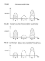
- FIG. 4A is a graph showing waveforms of the voice signals used for obtaining the target-sound enhancement waveforms and the nontarget-sound enhancement waveforms;
- FIG. 4B is a graph of the target-sound enhancement waveforms obtained on the basis of the voice signals shown in FIG. 4A ;
- FIG. 4C is a graph of the nontarget-sound enhancement waveforms obtained on the basis of the voice signals shown in FIG. 4A ;
- FIG. 5 is a graph showing the ratio between the intensity of the target-sound enhancement waveform and the intensity of the nontarget-sound enhancement waveform
- FIGS. 6A to 6C are graphs showing frequency spectra obtained by the Fourier transform performed on the original waveform, the target-sound enhancement waveform, and the nontarget-sound enhancement waveform, which are shown in FIGS. 4A to 4C ;
- FIG. 7 is a graph showing the time frame
- FIG. 8 is a flowchart showing the operation of the terminal device in the exemplary embodiment
- FIG. 9 is a flowchart further specifically describing the determination of the speaker, which is performed at step 107 in FIG. 8 ;
- FIG. 10 is a flowchart further specifically describing the determination of the speaker, which is performed at the step 107 in FIG. 8 , in cases of the other speakers not less than two;
- FIGS. 11A and 11B are graphs showing an example of the speaking information in a conversational situation.
- FIG. 1 is a diagram showing an example of a configuration of a sound analysis system according to the exemplary embodiment.
- a voice analysis system 1 of the exemplary embodiment includes a terminal device 10 as one example of a voice analysis device, and a host device 20 as one example of a sound analysis device.
- the terminal device 10 and the host device 20 are connected through a predetermined communication line.
- This communication line may be a wired communication line or a wireless communication line. If the wireless communication line is used, a line on which a known method such as Wi-Fi (Wireless Fidelity), Bluetooth (registered trademark in Japan), ZigBee, or UWB (Ultra Wideband) is employed may be Used. Note that, although only one terminal device 10 is shown in FIG. 1 , plural terminal devices 10 may be installed.
- FIG. 2 is a diagram showing an example of a functional configuration of the terminal device 10 and the host device 20 in the exemplary embodiment.
- the terminal device 10 includes plural microphones 11 , 12 , and 13 (a first microphone 11 , a second microphone 12 , and a third microphone 13 ) as voice acquiring units that acquire voice of a speaker, and an amplifier 14 .
- the terminal device 10 further includes a voice analysis unit 15 analyzing the acquired voice, a data transmitting unit 16 for transmitting the analysis result to the host device 20 , and a power source 17 .
- the first microphone 11 , the second microphone 12 , and the third microphone 13 are disposed at peak positions of a regular triangle, which will be described in detail with reference to FIG. 3 .
- the first microphone 11 , the second microphone 12 , and the third microphone 13 are arranged along the horizontal plane, for example.
- the microphones used as the first microphone 11 , the second microphone 12 , and the third microphone 13 of the exemplary embodiment may be chosen from existing microphones of various types such as a dynamic type and a condenser type.
- an omnidirectional microphone of micro electro mechanical systems (MEMS) may be chosen.
- the amplifier 14 amplifies electric signals (voice signals) which are output from the first microphone 11 , the second microphone 12 , and the third microphone 13 in response to the acquired sound.
- An amplifier such as an existing operational amplifier may be used as the amplifier 14 in the exemplary embodiment.
- the voice analysis unit 15 analyzes the voice signals output from the amplifier 14 .
- the voice analysis unit 15 identifies which speaker has speaking voice corresponding to the voice acquired by the first microphone 11 , the second microphone 12 , and the third microphone 13 . Specific contents of the processing for the voice identification will be described later.
- the voice analysis unit 15 functions as one example of a voice information acquiring unit and an identification unit.
- the data transmitting unit 16 transmits the acquired data including the analysis result from the voice analysis unit 15 , to the host device 20 via the aforementioned wireless communication line or a wired communication line such as the Internet in addition to the wireless communication line.
- the information transmitted to the host device 20 may include information such as time when the voice is acquired by the first microphone 11 , the second microphone 12 and the third microphone 13 , and the pressure of the acquired voice in addition to the aforementioned analysis result, depending on the contents of the processing performed by the host device 20 .
- a data storage unit for storing the analysis result from the voice analysis unit 15 may be provided in the terminal device 10 to collectively transmit the data stored in a certain period. Note that the information may be transmitted via only the wired communication line.
- the power source 17 supplies electric power to the first microphone 11 , the second microphone 12 , the third microphone 13 , the amplifier 14 , the voice analysis unit 15 , and the data transmitting unit 16 , which have been described above.
- a known power source such as a dry-cell battery or a rechargeable battery is used as the power source.
- the power source 17 includes a known circuit such as a voltage conversion circuit or a recharge control circuit, if necessary.
- the host device 20 includes a data receiving unit 21 that receives the data transmitted from the terminal device 10 , a data storage unit 22 in which the received data is stored, a data analysis unit 23 that analyzes the stored data, and an output unit 24 that outputs the analysis result.
- the host device 20 is realized by, for example, an information processor such as a personal computer. If the plural terminal devices 10 are used in the exemplary embodiment, the host device 20 receives data from the plural terminal devices 10 .
- a relay device that relays data transfer may be provided between the terminal device 10 and the host device 20 . In this case, the relay device may have a function for performing analysis and calculation, and adding data such as time, and the ID of the relay server.
- the data receiving unit 21 receives data from the respective terminal devices 10 or the relay device, and transmits the data to the data storage unit 22 .
- the data storage unit 22 is realized by, for example, a memory such as a magnetic disk drive of a personal computer, and the received data acquired from the data receiving unit 21 is stored in the data storage unit 22 .
- the data analysis unit 23 is realized by, for example, a CPU controlled by a program in a personal computer, and the data analysis unit 23 analyzes the data stored in the data storage unit 22 .
- the specific contents and technique of the analysis may be chosen from various contents and techniques, depending on the utilization purpose or configuration of the system in the exemplary embodiment. For example, a frequency of conversation between speakers or tendency of a speaker regarding a conversation partner may be analyzed, or relationship with a conversation partner may be estimated on the basis of the length of each speaking in the conversation and information of sound pressure.
- the data analysis unit 23 determines the conversational relationship between a target speaker and the other speaker in the exemplary embodiment, which will be described in detail below.
- the output unit 24 outputs analysis result from the data analysis unit 23 , and outputs data based on the analysis result.
- the unit outputting the analysis result and the like may be chosen from various units using a web display, display, print output by a printer, and audio output, depending on the utilization purpose and configuration of the system, the contents and format of the analysis result, and the like.
- FIG. 3 is a diagram showing a positional relationship between the terminal device 10 and each of mouths (speaking sections) of speakers.
- one speaker is chosen as a target speaker.
- the terminal device 10 identifies whether the voice of the speaker acquired by the microphones 11 , 12 and 13 corresponds to the speaking voice of the target speaker or speaking voice of a speaker other than the target speaker.
- FIG. 3 shows a situation where the target speaker X and a speaker Y other than the target speaker make a conversation around the terminal device 10 .
- Positional relationships between the first microphone 11 , the second microphone 12 , a sound source a as the speaking section of the target speaker X and a sound source b as the speaking section of the speaker Y will be assessed under the situation.
- the distance between the sound source a and the first microphone 11 is set at La 1
- the distance between the sound source a and the second microphone 12 is set at La 2 in the relationship shown in FIG. 3 .
- the distance between the sound source b and the first microphone 11 is set at Lb 1
- the distance between the sound source b and the second microphone 12 is set at Lb 2 .
- the speaking voice of the target speaker X from the sound source a travels to and reaches each of the first microphone 11 and the second microphone 12 through the air at the speed of sound. If La 1 and La 2 are different from each other, time difference between the time when the speaking voice reaches the first microphone 11 and the time when the speaking voice reaches the second microphone 12 is caused in accordance with the difference between the distances. The same is true in the case of the speaker Y. That is, the time difference between the time when the voice of the speaker Y from the sound source b reaches the first microphone 11 and the time when the voice of the speaker Y from the sound source b reaches the second microphone 12 is caused in accordance with the difference between the distance Lb 1 and the distance Lb 2 .
- the voice signals output from the first microphone 11 and the second microphone 12 have approximately the same waveform for each of the target speaker X and the speaker Y, the phase difference between the voice signals is generated in accordance with the time difference.
- the phase difference between the voice signals is used to identify which speaker has the speaking voice corresponding to the voice of the speaker acquired by the microphones 11 , 12 and 13 in the exemplary embodiment.
- a target-sound enhancement waveform in which the voice signal of the target speaker X has been enhanced and a nontarget-sound enhancement waveform (a second enhanced waveform) in which the voice signal of the speaker Y other than the target speaker X has been enhanced are firstly calculated.
- Examples of enhancing the target sound include amplification of a signal from a certain direction (direction where the target sound is produced), amplification of a signal from the certain direction and suppression of signals from the other directions, suppression of signals from the other directions without processing the signal from the certain direction, and extraction of the voice only from the certain direction.
- the target-sound enhancement waveform and the nontarget-sound enhancement waveform may be calculated by a known method. Specifically, they may be calculated by a method using a spatial filter utilizing the aforementioned phase difference, for example.
- FIG. 4A is a graph showing waveforms of the voice signals used for obtaining the target-sound enhancement waveforms and the nontarget-sound enhancement waveforms.
- the horizontal axis indicates time
- the vertical axis indicates the intensity of the voice signals.
- the figure shows the waveforms of the voice signals output from any of the first microphone 11 and the second microphone 12 , and they are referred to as original waveforms. Note that the actual waveforms of the voice signals have a saw-tooth shape. However, illustration thereof is simplified by using a spindle shape to make the description easier.
- FIG. 4A shows the voice signals in the case where the target speaker X speaks first, the speaker Y speaks next, and then the target speaker X and the speaker Y speak at the same time.
- the speaking period of the target speaker X is firstly shown, and then the speaking period of the target speaker Y is shown in FIG. 4A .
- the simultaneous speaking period which is the speaking period of the target speaker X and is also the speaking period of the speaker Y is lastly shown.
- FIG. 4B is a graph of the target-sound enhancement waveforms obtained on the basis of the voice signals shown in FIG. 4A .
- the intensity of the voice signal at the speaking period of the target speaker X is increased, whereas the intensity of the voice signal at the speaking period of the speaker Y is decreased in comparison with the case in FIG. 4A . That is, the waveforms in which the voice of the target speaker X has been enhanced are obtained.
- the voice signal at the simultaneous speaking period of the target speaker X and the speaker Y is expressed by a synchronized waveform in which the increased voice signal of the target speaker X and the decreased voice signal of the speaker Y have been synchronized.
- FIG. 4C is a graph of the nontarget-sound enhancement waveforms obtained on the basis of the voice signals shown in FIG. 4A .
- the intensity of the voice signal at the speaking period of the target speaker X is decreased, whereas the intensity of the voice signal at the speaking period of the speaker Y is increased in comparison with the case in FIG. 4A . That is, the waveforms in which the voice of the speaker Y has been enhanced are obtained.
- the voice signal at the simultaneous speaking period of the target speaker X and the speaker Y is expressed by a synchronized waveform in which the decreased voice signal of the target speaker X and the increased voice signal of the speaker Y have been synchronized.
- FIG. 5 is a graph showing the ratio between the intensity of the target-sound enhancement waveform and the intensity of the nontarget-sound enhancement waveform.
- the ratio between the intensities is obtained by (the intensity of the target-sound enhancement waveform in FIG. 4B )/(the intensity of the nontarget-sound enhancement waveform in FIG. 4C ).
- the intensity of the voice signal in the target-sound enhancement waveform is increased whereas the intensity of the voice signal in the nontarget-sound enhancement waveform is decreased, at the speaking period of the target speaker X.
- the ratio between the intensities is larger than 1.
- the intensity of the voice signal in the target-sound enhancement waveform is decreased whereas the intensity of the voice signal in the nontarget-sound enhancement waveform is increased, at the speaking period of the speaker Y.
- the ratio between the intensities is less than 1.
- the speaking voice is determined to correspond to the target speaker X when the ratio between the intensities is larger than the threshold, and the speaking voice is determined to correspond to the speaker Y when the ratio between the intensities is less than the threshold.
- the threshold is set around 1.2 in FIG. 5 .
- the ratio between the intensities at the simultaneous speaking period of the target speaker X and the speaker Y is the value between the value at the speaking period of the target speaker X and the value at the speaking period of the target speaker Y.
- the ratio between the intensities is unstable in comparison with the case where only the target speaker X or the speaker Y speaks.
- the value thereof tends to vary considerably, and the simultaneous speaking is difficult to be determined by the method in which the threshold is set.
- the period is determined to be the speaking period of any one of the target speaker X and the speaker Y, and incorrect determination is caused.
- the above problem may be reduced by a following method for discriminating between the speaking voice of the target speaker X and the speaking voice of the speaker Y.
- the Fourier transform is performed on each of the target-sound enhancement waveform and the nontarget-sound enhancement waveform, and the frequency spectra are obtained. Then, the speaker corresponding to the acquired voice is identified on the basis of the intensity of the peak in each of the frequency spectra.
- FIGS. 6A to 6C are graphs showing frequency spectra obtained by the Fourier transform performed on the original waveform, the target-sound enhancement waveform, and the nontarget-sound enhancement waveform, which are shown in FIGS. 4A to 4C .
- the horizontal axis indicates the frequency
- the vertical axis indicates the intensity. Note that a time frame F is set in the simultaneous speaking period of the target speaker X and the speaker Y as shown in FIG. 7 , and the Fourier transform is performed on each of the original waveform, the target-sound enhancement waveform and the nontarget-sound enhancement waveform in the time frame F.
- peaks are detected in the waveforms of the frequency spectra in FIGS. 6A to 6C .
- the detected peaks are denoted by I to VII.
- the peaks I to III, and V are common in FIG. 6A and FIG. 6B .
- the peaks V to VII are common in FIG. 6A and FIG. 6C . Note that, since the peak IV is not common, it is excluded from the detection.
- the ratio between the intensities of the peaks at the same frequency is calculated.
- the acquired voice is determined to be the speaking voice of the target speaker X.
- the first threshold is exceeded at any of the peaks I to III and V.
- the acquired voice is determined to be the speaking voice of the target speaker X.
- the first threshold is exceeded at the peaks I to III.
- the acquired voice is determined to be the speaking voice of the speaker Y.
- the second threshold is exceeded at any of the peaks V to VII.
- the acquired voice is determined to be the speaking voice of the speaker Y.
- the second threshold is exceeded at all of the peaks V to VII.
- the section at the time frame F is determined to be the speaking period of the target speaker X and the speaking period of the speaker Y. That is, it is determined to be the simultaneous speaking period of the target speaker X and the speaker Y.
- the determination of which speaker has made the speaking voice is performed on the basis of each ratio between the intensities of the peaks at the same frequency in this example.
- the determination is not limited to the above, and may be performed on the basis of the difference between the intensities.
- the peaks at the same frequencies in at least two of the frequency spectra containing a frequency spectrum of the original waveform, the target-sound enhancement waveform, and the nontarget-sound enhancement waveform are found in the exemplary embodiment.
- the intensities of the peaks at the same frequencies are used to identify which speaker has the speaking voice corresponding to the acquired voice. More specifically, the magnitude relationship between the intensities of the peaks at the same frequencies is used to identify which speaker has the speaking voice corresponding to the acquired voice.
- the frequency spectrum differs between speakers, and the frequencies at which the peaks in the frequency spectrum are located also differ between speakers.
- the peaks are distinguished in the frequency spectrum even in the case of the simultaneous speaking. Consequently, a speaker who has spoken may be identified on the basis of the frequencies at which the peaks are located.
- the frequencies at which the peaks corresponding to the speaking voice of the target speaker X in the frequency spectrum are located do not change between the frequency spectrum of the original waveform and the frequency spectrum of the target-sound enhancement waveform.
- the intensity of the frequency spectrum of the target-sound enhancement waveform is enhanced in comparison with the intensity of the frequency spectrum of the original waveform. Note that the peaks are lowered in the frequency spectrum of the nontarget-sound enhancement waveform.
- whether the target speaker X has spoken is determined on the basis of comparison between the intensities of the peaks in the frequency spectrum of the target-sound enhancement waveform and the intensities of the peaks in the frequency spectrum of the original waveform.
- the frequencies at which the peaks corresponding to the speaking voice of the speaker Y in the frequency spectrum are located do not change between the frequency spectrum of the original waveform and the frequency spectrum of the nontarget-sound enhancement waveform.
- the intensity in the frequency spectrum of the nontarget-sound enhancement waveform is enhanced in comparison with the intensity in the frequency spectrum of the original waveform. Note that the peaks are lowered in the frequency spectrum of the target-sound enhancement waveform.
- This method is available to determine if the target speaker X speaks or not and if the speaker Y speaks or not even in the case of the simultaneous speaking of the target speaker X and the speaker Y, in addition to the cases where any one of the target speaker X and the speaker Y speaks.
- FIG. 8 is a flowchart showing the operation of the terminal device 10 in the exemplary embodiment.
- step 101 if the microphones 11 , 12 and 13 of the terminal device 10 acquire voice (step 101 ), electric signals (voice signals) according to the acquired voice are transmitted to the amplifier 14 from the microphones 11 , 12 and 13 .
- the amplifier 14 Upon receiving the voice signals from the microphones 11 , 12 and 13 , the amplifier 14 amplifies the voice signals, and transmits the resultant signals to the voice analysis unit 15 (step 102 ).
- the voice analysis unit 15 calculates the target-sound enhancement waveform and the nontarget-sound enhancement waveform on the basis of the transmitted voice signals (original waveforms), by using a spatial filter utilizing a phase difference (step 103 ).
- the voice analysis unit 15 sets the time frame F for each certain time unit (for example, one several tenths seconds to one several hundredths seconds), the Fourier transform is performed on the original waveform, the target-sound enhancement waveform, and the nontarget-sound enhancement waveform to obtain the frequency spectra (step 104 ).
- the voice analysis unit 15 detects peaks from the respective waveforms of the frequency spectra (step 105 ).
- step 107 the determination of which speaker has spoken at the speaking period corresponding to the section at the time frame F is performed on the basis of the intensities of the peaks at the same frequencies.
- the voice analysis unit 15 transmits the information obtained in the processing from step 103 to step 107 (presence or absence of speaking, information on the speaker) as the analysis result to the host device 20 through the data transmitting unit 16 (step 108 ).
- the length of the speaking time of each speaker or additional information may be transmitted to the host device 20 together with the analysis result.
- FIG. 9 is a flowchart further specifically describing the determination of the speaker, which is performed at step 107 in FIG. 8 .
- the voice analysis unit 15 firstly sets 1 in the counter i (step 201 ).
- the voice analysis unit 15 determines if a i >c i >b i is satisfied or not (step 202 ). In other words, determination of which speaker has made speaking voice is performed on the basis of the difference between the intensities.
- the speaking flag f i is set as the “target speaker” (step 203 ).
- the voice analysis unit 15 determines if b i >c i >a i is satisfied or not (step 204 ).
- the speaking flag f i is set as “the other speaker” (step 205 ).
- the voice analysis unit 15 adds 1 to the counter i (step 206 ). Then, the voice analysis unit 15 determines if i>n is satisfied (step 207 ). If i>n is not satisfied (No at step 207 ), the process goes back to the step 202 .
- the voice analysis unit 15 determines that the section at the time frame F is the simultaneous speaking period of the target speaker X and the speaker Y (step 210 ).
- the voice analysis unit 15 determines that the section at the time frame F is the speaking period of only the target speaker X (step 211 ).
- the voice analysis unit 15 determines that the section at the time frame F is the speaking period of only the speaker Y (step 213 ).
- the voice analysis unit 15 determines that the section at the time frame F is the period where no one, none of the target speaker X and the speaker Y, speaks (step 214 ).
- the speakers are not limited to the above, and the number of the speakers may be three or more.
- “the other speakers” are two or more speakers.
- the nontarget-sound enhancement waveforms are calculated in addition to the target-sound enhancement waveform at step 103 . Then, by performing the similar processing in steps 104 to 107 , the determination of which speaker has spoken at the speaking period corresponding to the section at the time frame F is performed.
- the determination of the speaker which is performed at the step 107 , is performed as follows.
- FIG. 10 is a flowchart further specifically describing the determination of the speaker, which is performed at the step 107 in FIG. 8 , in cases of the other speakers not less than two.
- the total number of the target speaker X and the other speakers is m. That is, the number of the other speakers is regarded as m ⁇ 1.
- the intensities of the n peaks at the frequencies ⁇ in the frequency spectra of the nontarget-sound enhancement waveforms are expressed by ⁇ a 21 , a 22 , a 23 , . . . , a 2n ⁇ , ⁇ a 31 , a 32 , a 33 , . . . , a 3n ⁇ , . . . , and ⁇ a m1 , a m2 , a m3 , . . . , a mn ⁇ .
- the intensity A obtained by summing up the above intensities is given as below. Note that it may be recognized as a matrix composed of m rows and n columns.
- A ⁇ a 11 , a 12 , a 13 , ... ⁇ , a 1 ⁇ n , a 21 , a 22 , a 23 , ... ⁇ , a 2 ⁇ n , a 31 , a 32 , a 33 , ... ⁇ , a 3 ⁇ n , ... ⁇ ⁇ a m ⁇ ⁇ 1 , a m ⁇ ⁇ 2 , a m ⁇ ⁇ 3 , ... ⁇ , a mn ⁇
- the voice analysis unit 15 firstly sets 1 in the counter i (step 301 ).
- T ⁇ a 1i a 3i a ni ⁇ is obtained.
- step 303 whether the number of the elements of T is not less than one is determined.
- f 1 is set at 1, 3 and n.
- step 303 If the number of the elements in T is less than one (that is, zero) (No at step 303 ), the process goes to step 305 .
- the voice analysis unit 15 adds one to the counter i (step 305 ). Then, the voice analysis unit 15 determines if i>n is satisfied or not (step 306 ). If i>n is not satisfied (No at step 306 ), the process goes back to step 302 .
- the voice analysis unit 15 determines that the speakers corresponding to the extracted row numbers have spoken at the time frame F. For example, if 1 is extracted as the row number, the target speaker X has spoken. Alternatively, if m is extracted for example, the speaker corresponding to this number has spoken. The voice analysis unit 15 performs determination of which speaker has spoken at the speaking period corresponding to the section at the time frame F, on the basis of the extracted row numbers (step 308 ).
- the aforementioned terminal device 10 may identifies the simultaneous speaking even in the case where plural speakers speak at the same time, and identifies which speaker has spoken. Thus, the accuracy of identification of speakers is less likely to be reduced.
- the data analysis unit 23 analyses the voice transmitted from the plural terminal devices 10 , and determines the conversational relationship between users.
- FIGS. 11A and 11B are graphs showing an example of the speaking information in a conversational situation.
- the speaking information indicates that pieces of information indicating a speaking situation, such as the length of the speaking time and the timing when the speaker changes to the other are similar, and the pieces of the information are synchronized, as shown in FIGS. 11A and 11B .
- the host device 20 of this example analyses the pieces of information acquired from the terminal devices 10 to determine the synchronization, and thereby determines that the pieces of the information indicate the same speaking situation. Consequently, conversation between the target speaker X and the speaker Y is recognized.
- Temporal information on the speaking at least including the length of the each speaking time of the aforementioned speakers, start time and end time of each speaking, and time (timing) when the speaker changes is used as the pieces of the information indicating the speaking situation. Note that part of the temporal information on the speaking may be used, or another information may be additionally used, to determine the speaking situation of specific conversation.
- the identification of the speaker corresponding to the voice is performed by the terminal device 10 in the above example, it is not limited to the above, and may be performed by the host device 20 .
- the voice analysis system 1 in this case performs the identification of the speaker corresponding to the voice signal, by using, for example, the data analysis unit 23 of the host device 20 instead of the voice analysis unit 15 in FIG. 1 .
- the data analysis unit 23 functions as a voice information acquiring unit and an identification unit.
- the determination of the conversational situation described in FIGS. 11A and 11B may be performed by the voice analysis unit 15 of the terminal device 10 instead of the data analysis unit 23 .
- the identification of the speaker is performed by using the first microphone 11 and the second microphone 12 in the above example, it is not limited to the above, and the third microphone 13 may be used. Alternatively, appropriate two of the first microphone 11 , the second microphone 12 , and the third microphone 13 may be chosen.
- the processing performed by the terminal device 10 in the exemplary embodiment is achieved by causing the software and a hardware resource to work together. That is, the CPU placed on the inside of the control computer in the terminal device 10 , which is not shown, executes a program for achieving respective functions of the terminal device 10 , and enables the respective functions to be achieved.
- the processing performed by the terminal device 10 may be taken as a program for enabling a computer to achieve a voice information acquiring function that acquires a voice signal generated by plural voice acquiring units disposed at different distances from a speaking section of a speaker and acquiring voice of the speaker, and an identification function that identifies the speaker corresponding to the voice having been acquired, on the basis of intensities of respective peaks in frequency spectra of a target-sound enhancement waveform and a nontarget-sound enhancement waveform, the target-sound enhancement waveform being a waveform where a voice signal of a predetermined target speaker has been enhanced, the nontarget-sound enhancement waveform being a waveform where a voice signal of a speaker other than the target speaker has been enhanced.
Landscapes
- Engineering & Computer Science (AREA)
- Physics & Mathematics (AREA)
- Health & Medical Sciences (AREA)
- Audiology, Speech & Language Pathology (AREA)
- Human Computer Interaction (AREA)
- Acoustics & Sound (AREA)
- Multimedia (AREA)
- Signal Processing (AREA)
- Computational Linguistics (AREA)
- Quality & Reliability (AREA)
- Circuit For Audible Band Transducer (AREA)
- Obtaining Desirable Characteristics In Audible-Bandwidth Transducers (AREA)
- Telephone Function (AREA)
- Business, Economics & Management (AREA)
- Computer Vision & Pattern Recognition (AREA)
- Game Theory and Decision Science (AREA)
- Spectroscopy & Molecular Physics (AREA)
Abstract
Description
Claims (9)
Applications Claiming Priority (2)
| Application Number | Priority Date | Filing Date | Title |
|---|---|---|---|
| JP2015-041710 | 2015-03-03 | ||
| JP2015041710A JP6515591B2 (en) | 2015-03-03 | 2015-03-03 | Speech analysis device, speech analysis system and program |
Publications (2)
| Publication Number | Publication Date |
|---|---|
| US20160260439A1 US20160260439A1 (en) | 2016-09-08 |
| US9704504B2 true US9704504B2 (en) | 2017-07-11 |
Family
ID=56847318
Family Applications (1)
| Application Number | Title | Priority Date | Filing Date |
|---|---|---|---|
| US14/791,794 Expired - Fee Related US9704504B2 (en) | 2015-03-03 | 2015-07-06 | Voice analysis device and voice analysis system |
Country Status (2)
| Country | Link |
|---|---|
| US (1) | US9704504B2 (en) |
| JP (1) | JP6515591B2 (en) |
Families Citing this family (2)
| Publication number | Priority date | Publication date | Assignee | Title |
|---|---|---|---|---|
| US10564925B2 (en) * | 2017-02-07 | 2020-02-18 | Avnera Corporation | User voice activity detection methods, devices, assemblies, and components |
| US20190267009A1 (en) * | 2018-02-27 | 2019-08-29 | Cirrus Logic International Semiconductor Ltd. | Detection of a malicious attack |
Citations (2)
| Publication number | Priority date | Publication date | Assignee | Title |
|---|---|---|---|---|
| US20090296526A1 (en) | 2008-06-02 | 2009-12-03 | Kabushiki Kaisha Toshiba | Acoustic treatment apparatus and method thereof |
| JP2014191069A (en) * | 2013-03-26 | 2014-10-06 | Fuji Xerox Co Ltd | Voice analysis device, voice analysis system, and program |
Family Cites Families (4)
| Publication number | Priority date | Publication date | Assignee | Title |
|---|---|---|---|---|
| JP2005173007A (en) * | 2003-12-09 | 2005-06-30 | Canon Inc | Speech analysis processing and speech processing apparatus and medium using the same |
| JP2013135325A (en) * | 2011-12-26 | 2013-07-08 | Fuji Xerox Co Ltd | Voice analysis device |
| JP6003472B2 (en) * | 2012-09-25 | 2016-10-05 | 富士ゼロックス株式会社 | Speech analysis apparatus, speech analysis system and program |
| JP6056544B2 (en) * | 2013-02-26 | 2017-01-11 | 富士ゼロックス株式会社 | Speech analysis device, signal analysis device, speech analysis system, and program |
-
2015
- 2015-03-03 JP JP2015041710A patent/JP6515591B2/en not_active Expired - Fee Related
- 2015-07-06 US US14/791,794 patent/US9704504B2/en not_active Expired - Fee Related
Patent Citations (3)
| Publication number | Priority date | Publication date | Assignee | Title |
|---|---|---|---|---|
| US20090296526A1 (en) | 2008-06-02 | 2009-12-03 | Kabushiki Kaisha Toshiba | Acoustic treatment apparatus and method thereof |
| JP2009288215A (en) | 2008-06-02 | 2009-12-10 | Toshiba Corp | Acoustic processing device and method therefor |
| JP2014191069A (en) * | 2013-03-26 | 2014-10-06 | Fuji Xerox Co Ltd | Voice analysis device, voice analysis system, and program |
Also Published As
| Publication number | Publication date |
|---|---|
| JP2016163230A (en) | 2016-09-05 |
| US20160260439A1 (en) | 2016-09-08 |
| JP6515591B2 (en) | 2019-05-22 |
Similar Documents
| Publication | Publication Date | Title |
|---|---|---|
| US8892424B2 (en) | Audio analysis terminal and system for emotion estimation of a conversation that discriminates utterance of a user and another person | |
| EP2541543B1 (en) | Signal processing apparatus and signal processing method | |
| JP6003472B2 (en) | Speech analysis apparatus, speech analysis system and program | |
| JP6031761B2 (en) | Speech analysis apparatus and speech analysis system | |
| EP2355097B1 (en) | Signal separation system and method | |
| KR20120080409A (en) | Apparatus and method for estimating noise level by noise section discrimination | |
| JP6276132B2 (en) | Utterance section detection device, speech processing system, utterance section detection method, and program | |
| JP6003510B2 (en) | Speech analysis apparatus, speech analysis system and program | |
| JPWO2018037643A1 (en) | INFORMATION PROCESSING APPARATUS, INFORMATION PROCESSING METHOD, AND PROGRAM | |
| JP5867066B2 (en) | Speech analyzer | |
| US9704504B2 (en) | Voice analysis device and voice analysis system | |
| US20170309293A1 (en) | Method and apparatus for processing audio signal including noise | |
| CN109997186A (en) | A kind of device and method for acoustic environment of classifying | |
| CN111415678B (en) | Classifying open or closed space environments for mobile or wearable devices | |
| JP6165046B2 (en) | Sound source position estimation method, estimation apparatus, and estimation program | |
| JP2013142843A (en) | Operation analyzer, voice acquisition device, and operation analysis system | |
| JP6476938B2 (en) | Speech analysis apparatus, speech analysis system and program | |
| JP6007487B2 (en) | Information processing apparatus, information processing system, and program | |
| JP2014164164A (en) | Voice analysis device, signal analyzer, voice analysis system and program | |
| US9140774B2 (en) | Voice analyzer, voice analysis system, and non-transitory computer readable medium storing a program | |
| JP6191747B2 (en) | Speech analysis apparatus and speech analysis system | |
| JP5929810B2 (en) | Voice analysis system, voice terminal apparatus and program | |
| JP2017040752A (en) | Voice determining device, method, and program, and voice signal processor | |
| JP2013140534A (en) | Voice analysis device, voice analysis system, and program | |
| JP6051996B2 (en) | Speech analysis apparatus, speech analysis system and program |
Legal Events
| Date | Code | Title | Description |
|---|---|---|---|
| AS | Assignment |
Owner name: FUJI XEROX CO., LTD., JAPAN Free format text: ASSIGNMENT OF ASSIGNORS INTEREST;ASSIGNORS:INAGI, SEIYA;HARADA, HARUO;YONEYAMA, HIROHITO;AND OTHERS;REEL/FRAME:035982/0037 Effective date: 20150701 |
|
| STCF | Information on status: patent grant |
Free format text: PATENTED CASE |
|
| MAFP | Maintenance fee payment |
Free format text: PAYMENT OF MAINTENANCE FEE, 4TH YEAR, LARGE ENTITY (ORIGINAL EVENT CODE: M1551); ENTITY STATUS OF PATENT OWNER: LARGE ENTITY Year of fee payment: 4 |
|
| AS | Assignment |
Owner name: FUJIFILM BUSINESS INNOVATION CORP., JAPAN Free format text: CHANGE OF NAME;ASSIGNOR:FUJI XEROX CO., LTD.;REEL/FRAME:058287/0056 Effective date: 20210401 |
|
| FEPP | Fee payment procedure |
Free format text: MAINTENANCE FEE REMINDER MAILED (ORIGINAL EVENT CODE: REM.); ENTITY STATUS OF PATENT OWNER: LARGE ENTITY |
|
| LAPS | Lapse for failure to pay maintenance fees |
Free format text: PATENT EXPIRED FOR FAILURE TO PAY MAINTENANCE FEES (ORIGINAL EVENT CODE: EXP.); ENTITY STATUS OF PATENT OWNER: LARGE ENTITY |
|
| STCH | Information on status: patent discontinuation |
Free format text: PATENT EXPIRED DUE TO NONPAYMENT OF MAINTENANCE FEES UNDER 37 CFR 1.362 |
|
| FP | Lapsed due to failure to pay maintenance fee |
Effective date: 20250711 |