US969802A - Corliss valve-gear. - Google Patents
Corliss valve-gear. Download PDFInfo
- Publication number
- US969802A US969802A US44064008A US1908440640A US969802A US 969802 A US969802 A US 969802A US 44064008 A US44064008 A US 44064008A US 1908440640 A US1908440640 A US 1908440640A US 969802 A US969802 A US 969802A
- Authority
- US
- United States
- Prior art keywords
- plate
- hook
- latch
- valve
- block
- Prior art date
- Legal status (The legal status is an assumption and is not a legal conclusion. Google has not performed a legal analysis and makes no representation as to the accuracy of the status listed.)
- Expired - Lifetime
Links
- 238000010276 construction Methods 0.000 description 6
- 230000009514 concussion Effects 0.000 description 2
- 229910000831 Steel Inorganic materials 0.000 description 1
- 238000006073 displacement reaction Methods 0.000 description 1
- 230000000694 effects Effects 0.000 description 1
- 239000010985 leather Substances 0.000 description 1
- 230000010355 oscillation Effects 0.000 description 1
- 230000000284 resting effect Effects 0.000 description 1
- 239000010959 steel Substances 0.000 description 1
Images

Classifications
-
- H—ELECTRICITY
- H03—ELECTRONIC CIRCUITRY
- H03H—IMPEDANCE NETWORKS, e.g. RESONANT CIRCUITS; RESONATORS
- H03H3/00—Apparatus or processes specially adapted for the manufacture of impedance networks, resonating circuits, resonators
- H03H3/007—Apparatus or processes specially adapted for the manufacture of impedance networks, resonating circuits, resonators for the manufacture of electromechanical resonators or networks
- H03H3/0072—Apparatus or processes specially adapted for the manufacture of impedance networks, resonating circuits, resonators for the manufacture of electromechanical resonators or networks of microelectro-mechanical resonators or networks
- H03H3/0076—Apparatus or processes specially adapted for the manufacture of impedance networks, resonating circuits, resonators for the manufacture of electromechanical resonators or networks of microelectro-mechanical resonators or networks for obtaining desired frequency or temperature coefficients
-
- Y—GENERAL TAGGING OF NEW TECHNOLOGICAL DEVELOPMENTS; GENERAL TAGGING OF CROSS-SECTIONAL TECHNOLOGIES SPANNING OVER SEVERAL SECTIONS OF THE IPC; TECHNICAL SUBJECTS COVERED BY FORMER USPC CROSS-REFERENCE ART COLLECTIONS [XRACs] AND DIGESTS
- Y10—TECHNICAL SUBJECTS COVERED BY FORMER USPC
- Y10T—TECHNICAL SUBJECTS COVERED BY FORMER US CLASSIFICATION
- Y10T74/00—Machine element or mechanism
- Y10T74/11—Tripping mechanism
- Y10T74/111—Speed controlled
- Y10T74/113—Valve gear trips [e.g., steam engine "Corliss" type]
Definitions
- the present invention relates to the cutoff valve gear for the oscillating steamva-lve used in Corliss engines.
- Corliss valve-gear it has been common to mount upon the valve-stem an arm carrying a catch-block and to mount a rocker-plate upon the bearing of the valve-stem with a latch pivoted upon such rocker-plate to engage thecatch-block.
- a cam has been mounted to oscillate between the arm of the catch-block and the rockerplate, and the catch-block has been projected over such cam in line with the same, and the latch formed with two arms in the same plane, one the hook-arm carrying a hook to engage the catch-block and one, the leverarm extended inwardly over the cam to be actuated thereby.
- the catch-block and the cam are brought in line with one another by projecting the catch-block from the arm which carries it toward the rocker-plate.
- the objectof the present invention is to simplify the construction by dispensing with a separate lever arm upon the latch to be actuated by the cam-plate, and this is effected as follows.
- I substitute a so-called hook-plate for the valve-moving or catch-block arm, placing the catch-block upon the edge of such hook-plate.
- the latch lies directly over the edge of such hook-plate and carries a socalled hook to engage the ca.tch-block.
- a cam-plate is journaled to move close to the side of the catch-block upon the hook-plate, and the latch is formed with an offset finger projected laterally over the edge of the camplate to be actuated thereby. The cam thus operates upon the latch itself.
- the invention includes certain details of construction which facilitate the operation of the latch and its actuation by the camplate, and reduces the wear upon the offset finger which engages the cam-plate.
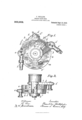
- FIG. l is a front elevation of the valvean edge view of the gear and the valve-stem bracket viewed from the left side of Fig. 3;
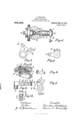
- Flg. 5 is a side elevation of the bracket and valvc-stem with the hook-plate upon the end of the stem;
- Fig. 6 is a front view of the rocker-plate;
- Fig. 7 is a front View of the hook-plate;
- Fig. 8 is a plan of the latch, and
- Fig. 9 is a front view of the latch and cam-plate.
- Fig. 10 shows the latch and part of the hook-plate in section lengthwise of the latch;
- Fig. 11 shows the under side of the latch, and
- Fig. 12 is a cross section of the latch and margin of the hookplate with the tooth in the mortise.
- a designates the valve-stem, and b the bracket-bearing in which the stem is commonly ournaled upon the end of the valve chest.
- 0 designates the hook-plate attached to the valve-stem a and having the catch-block d fitted radially thereon to engage the latch, and provided as shown in Fig. 1, with an arm a and rod f for connecting it to the dash-pot as usual.
- the bracket-bearing b as shown in Fig. 5, 1s formed adjacent to the end of the valvestem with two journals 9 and h which support, respectively, the cam-plate i and the I rocker-plate j.
- the rocker-plate has the arm I) for the usual eccentric connect-ion f.
- the cam-plate lies clOSe by the side of the hook-plate, between the same and the rocker-plate.
- the rocker-plate has a boss is projecting over the edge of the cam-plate, and the latch in is pivoted upon the said boss, in line with the edge of the hook-plate, by a pivot 7.5-, and is provided with the usual steel block or hook Z to engage the catch-block (Z.
- the working face of the cam i is of segmental form and it projects from the cam-plate upon the same side of the valve-stem as the catch-block, so as to move closely adjacent to the catch-block when actuated by the governor through the arm g connected to the governor-rod m.
- the segmental edge of the cam-plate is provided at one end with a raised seat 11, and the latch is provided with a laterally projecting or offset finger 0 having a renewable wearing piece p in line with the edge of the cam-plate and thus adapted to collide with the seat a and lift the latch from the catch-block, as required to close the valve.
- the end of the cam-face opposite to that formed with the seat a is provided with a safety-dog g which operates to detach the latch from the catch-block if the governor collapses, and thus permits the steam-valve to close at once in such event.
- a safety-dog g which operates to detach the latch from the catch-block if the governor collapses, and thus permits the steam-valve to close at once in such event.
- the tooth 1 has a shoulder 1" formed concentric with the pivot k of the latch and one end of the mortise s is similarly curved and so disposed that the tooth may drop into the mortise by a noiseless sliding movement exactly when the hook Z contacts with the catchblock d.
- the contact of the tooth with the end of the slot thus occurs at the same time as the contact of the hook with the catchblock and produces only a single click or concussion, thus avoiding any Lmnecessary multiplication of noises in the operation of the valve-gear.
- the spring '0 holds the tooth r normally in its operative position, but permits the tooth to slide slightly if the hook or catch-block become worn at their point of contact so as to throw any pressure upon the end 1" of the tooth.
- the tooth holds the latch normally raised during the oscillations of the rocker-plate as shown in Fig. 3, except when the hook is in the exact position to engage the catch-block, thus preserving the hook entirely from rubbing upon the face of the hook-plate.
- a leather facing-block w is shown upon the under side of the latch to soften its concussion with the edge of the hook-plate when the tooth falls into the mortise.
- the catch-block on the edge of a hookplate and projecting the segmental face of the cam-plate at the side of the catch-block upon such hook-plate; so that the end of the latch may be constructed to lie over both, and contact directly therewith.
- the catch-block and the cam-face of the cam plate are both projected at the same side of the valve-stem and movable close to one another, and the rocker-plate is movable at the side of the cam-plate to carry the latch in the proper relation to both the hookplate and the cam-plate.
- the latch By forming the boss 70' on the rockerplate to project over the edge of the camplate the latch is brought into line with the catch-block, so that its pull in opening the valve may be directly in line with its own pivot, and the engagement or cooperation of the latch with the cam-face being, in
Landscapes
- Engineering & Computer Science (AREA)
- Manufacturing & Machinery (AREA)
- Mechanically-Actuated Valves (AREA)
Description
F. PHILLIPS. GORLISS VALVE GEAR. APPLIOATION FILED JUNE 21, 1908.
Patented Sept. 13, 1910.
3 SHEETS-SHEET 1.
F. PHILLIPS. GORLISS VALVE GEAR. APPLICATION FILED JUNE 27,1908.
m 9 E A 3 4 L Wm Sm d e t n m a P ull F. PHILLIPS.
GORLISS VALVE GEAR,
APPLIUATION FILED mm". 21, 1908.
969,802. Patented Sept. 13, 1910.
3 SHEETS-SHEET 3.
MINNIE! 2311- Y FRANKLIN PHILLIPS, 0E NEWARK, NEW JERSEY.
CORLISS VALVE-GEAR.
Specification of Letters Patent.
Patented Sept. 13, 1910.
Application filed June 27, 1908. Serial No. 440,640.
T 0 all whom it may concern:
Be it known that I, FRANKLIN PHILLIPS, a citizen of the United States, residing at 539 Mount Prospect avenue, Newark, county of Essex, and State of New Jersey, have invented certain new and useful Improvements in Corliss Valve-Gear, fully described and represented in the following specification and the accompanying drawings, forming a part of the same.
The present invention relates to the cutoff valve gear for the oscillating steamva-lve used in Corliss engines. In such Corliss valve-gear, it has been common to mount upon the valve-stem an arm carrying a catch-block and to mount a rocker-plate upon the bearing of the valve-stem with a latch pivoted upon such rocker-plate to engage thecatch-block. In such construction, a cam has been mounted to oscillate between the arm of the catch-block and the rockerplate, and the catch-block has been projected over such cam in line with the same, and the latch formed with two arms in the same plane, one the hook-arm carrying a hook to engage the catch-block and one, the leverarm extended inwardly over the cam to be actuated thereby. The catch-block and the cam are brought in line with one another by projecting the catch-block from the arm which carries it toward the rocker-plate.
The objectof the present invention is to simplify the construction by dispensing with a separate lever arm upon the latch to be actuated by the cam-plate, and this is effected as follows. To carry the catchblock, I substitute a so-called hook-plate for the valve-moving or catch-block arm, placing the catch-block upon the edge of such hook-plate. The latch lies directly over the edge of such hook-plate and carries a socalled hook to engage the ca.tch-block. A cam-plate is journaled to move close to the side of the catch-block upon the hook-plate, and the latch is formed with an offset finger projected laterally over the edge of the camplate to be actuated thereby. The cam thus operates upon the latch itself.
The invention includes certain details of construction which facilitate the operation of the latch and its actuation by the camplate, and reduces the wear upon the offset finger which engages the cam-plate.
The invention will be understood by reference to the annexed drawing, in which- Figure l is a front elevation of the valvean edge view of the gear and the valve-stem bracket viewed from the left side of Fig. 3; Flg. 5 is a side elevation of the bracket and valvc-stem with the hook-plate upon the end of the stem; Fig. 6 is a front view of the rocker-plate; Fig. 7 is a front View of the hook-plate; Fig. 8 is a plan of the latch, and Fig. 9 is a front view of the latch and cam-plate. Fig. 10 shows the latch and part of the hook-plate in section lengthwise of the latch; Fig. 11 shows the under side of the latch, and Fig. 12 is a cross section of the latch and margin of the hookplate with the tooth in the mortise.
a designates the valve-stem, and b the bracket-bearing in which the stem is commonly ournaled upon the end of the valve chest.
0 designates the hook-plate attached to the valve-stem a and having the catch-block d fitted radially thereon to engage the latch, and provided as shown in Fig. 1, with an arm a and rod f for connecting it to the dash-pot as usual.
I The bracket-bearing b, as shown in Fig. 5, 1s formed adjacent to the end of the valvestem with two journals 9 and h which support, respectively, the cam-plate i and the I rocker-plate j. The rocker-plate has the arm I) for the usual eccentric connect-ion f. The cam-plate lies clOSe by the side of the hook-plate, between the same and the rocker-plate. The rocker-plate has a boss is projecting over the edge of the cam-plate, and the latch in is pivoted upon the said boss, in line with the edge of the hook-plate, by a pivot 7.5-, and is provided with the usual steel block or hook Z to engage the catch-block (Z. The working face of the cam i is of segmental form and it projects from the cam-plate upon the same side of the valve-stem as the catch-block, so as to move closely adjacent to the catch-block when actuated by the governor through the arm g connected to the governor-rod m. To actuate the latch at the desired point of cut-off, the segmental edge of the cam-plate is provided at one end with a raised seat 11, and the latch is provided with a laterally projecting or offset finger 0 having a renewable wearing piece p in line with the edge of the cam-plate and thus adapted to collide with the seat a and lift the latch from the catch-block, as required to close the valve. The end of the cam-face opposite to that formed with the seat a is provided with a safety-dog g which operates to detach the latch from the catch-block if the governor collapses, and thus permits the steam-valve to close at once in such event. In order that the camseat n and the dog 9 may operate upon the finger with equal facility, the wearing piece p upon the finger is beveled in opposite directions, so as to present a rounding face to the oppositely inclined projections 91 and g.
To preserve the face of the hook Z from wear when the hook-plate c is moved beneath it, I furnish a tooth 1" upon the bottom of the latch to sustain all the wear by resting upon the hook-plate until the hook is in position to engage the catch-block.-. At that instant the tooth falls into a mortise s in the margin of the hook-plate and remains therein until the latch is lifted by the cam-seat n. The tooth r is attached to a side 25 which is dovetailed into the under side of the latch, as shown in Figs. 10 to 12 inclusive, and held from displacement by a stop-piece a. A spring a; presses the slide constantly toward the stop -piece. The tooth 1 has a shoulder 1" formed concentric with the pivot k of the latch and one end of the mortise s is similarly curved and so disposed that the tooth may drop into the mortise by a noiseless sliding movement exactly when the hook Z contacts with the catchblock d. The contact of the tooth with the end of the slot thus occurs at the same time as the contact of the hook with the catchblock and produces only a single click or concussion, thus avoiding any Lmnecessary multiplication of noises in the operation of the valve-gear. The spring '0 holds the tooth r normally in its operative position, but permits the tooth to slide slightly if the hook or catch-block become worn at their point of contact so as to throw any pressure upon the end 1" of the tooth. It will be understood that the tooth holds the latch normally raised during the oscillations of the rocker-plate as shown in Fig. 3, except when the hook is in the exact position to engage the catch-block, thus preserving the hook entirely from rubbing upon the face of the hook-plate. A leather facing-block w is shown upon the under side of the latch to soften its concussion with the edge of the hook-plate when the tooth falls into the mortise.
With the use of a hook-plate, and a latch operating directly upon the hook-plate and of the segment 0 of the hook-plate just when the valve is closed. So long as the Valve is closed by the dash-pot this lug performs no function, but upon any failure of j the dash-pot to close the valve promptly the lug or post 71/ effects such closure positively.
It will be observed that the use of a leverarm extended from the pivot of'the latch to cooperate with the edge of a cam, is
avoided in the present construction by placing the catch-block on the edge of a hookplate and projecting the segmental face of the cam-plate at the side of the catch-block upon such hook-plate; so that the end of the latch may be constructed to lie over both, and contact directly therewith. To secure such an operation of the latch, the catch-block and the cam-face of the cam plate are both projected at the same side of the valve-stem and movable close to one another, and the rocker-plate is movable at the side of the cam-plate to carry the latch in the proper relation to both the hookplate and the cam-plate.
By forming the boss 70' on the rockerplate to project over the edge of the camplate the latch is brought into line with the catch-block, so that its pull in opening the valve may be directly in line with its own pivot, and the engagement or cooperation of the latch with the cam-face being, in
such construction easily effected by projecting the offset finger 0 laterally from the side of the latch.
Having thus set forth the nature of the invention what is claimed herein is:
1. In a Corliss valve-gear, the combination, with a segmental hook-plate attached to the valve-stem and a rocker-plate oscillated by theside of the same, of the post ,or lug h projected from the rocker-plate past the rear edge of the hook-plate and disposed to positively close the valve when required, by pressure upon the edge of the hook-plate.
2. In a Corliss valve-gear, the combination, with a segmental hook-plate having the catch-block d upon its forward edge and mortise 8 adjacent thereto, and a rockerplate oscillated by the side of such hookplate, of a latch pivoted uponv the rockerplate and movable in line with the edge of the hookplate, and having the hook Z to engage the catch-block, and the tooth r to rest upon the face of the hook-plate and adapted to enter the mortise when the hook engages the catch-block.
3. In a Corliss valve-gear, the combination, with a segmental hook-plate having the catch-block d upon its forward edge and mortise 8 adjacent thereto and a rocker plate oscillated by the side of such hookplate, of a latch pivoted upon the rockerplate and movable in line with the edge of the hook-plate, and having the hook Z to engage the catch-block, the slide t movable in the under side of the latch with tooth 0" projected therefrom, the spring 2) to press the slide endwise, and the stop u to limit such end movement, the construction operating to relieve the tooth from any longitudinal pressure.
In testimony whereof I have hereunto set my hand in the presence of two subscribing witnesses.
FRANKLIN PHILLIPS. WVitnesses:
L. LEE, THOMAS S. CRANE.
Priority Applications (1)
| Application Number | Priority Date | Filing Date | Title |
|---|---|---|---|
| US44064008A US969802A (en) | 1908-06-27 | 1908-06-27 | Corliss valve-gear. |
Applications Claiming Priority (1)
| Application Number | Priority Date | Filing Date | Title |
|---|---|---|---|
| US44064008A US969802A (en) | 1908-06-27 | 1908-06-27 | Corliss valve-gear. |
Publications (1)
| Publication Number | Publication Date |
|---|---|
| US969802A true US969802A (en) | 1910-09-13 |
Family
ID=3038192
Family Applications (1)
| Application Number | Title | Priority Date | Filing Date |
|---|---|---|---|
| US44064008A Expired - Lifetime US969802A (en) | 1908-06-27 | 1908-06-27 | Corliss valve-gear. |
Country Status (1)
| Country | Link |
|---|---|
| US (1) | US969802A (en) |
-
1908
- 1908-06-27 US US44064008A patent/US969802A/en not_active Expired - Lifetime
Similar Documents
| Publication | Publication Date | Title |
|---|---|---|
| US439619A (en) | Island | |
| US1078305A (en) | Motor or engine. | |
| US483328A (en) | Valve-gear for steam-engines | |
| US31272A (en) | Steam-engine | |
| US1003165A (en) | Valve-release mechanism for steam-engines. | |
| US526267A (en) | Island | |
| US1077898A (en) | Valve-gear for steam-engines. | |
| US815833A (en) | Governing mechanism for turbines. | |
| US1419435A (en) | Signal-governing apparatus | |
| US215797A (en) | Improvement in valve-gears for steam-engines | |
| US210059A (en) | Improvement in valve-gears for engines | |
| US649407A (en) | Safety-stop for steam-engines. | |
| US1475123A (en) | Valve-actuating means | |
| US250729A (en) | hayward | |
| US1050618A (en) | Valve-gear for steam-engines. | |
| US475691A (en) | krotz | |
| US473085A (en) | Island | |
| US1005741A (en) | Valve trip-gear for steam and other motive-power engines. | |
| US406904A (en) | Geoege ii | |
| US485433A (en) | Steam-engine valve-gear | |
| US1096259A (en) | Valve mechanism for engines. | |
| US764490A (en) | Valve-gear. | |
| US954011A (en) | Turbine-governing mechanism. | |
| US2383534A (en) | Locomotive drifting control mechanism | |
| USRE761E (en) | Island |