US9694997B2 - Delivery ramp with an adjustable, rotatable pivot - Google Patents
Delivery ramp with an adjustable, rotatable pivot Download PDFInfo
- Publication number
- US9694997B2 US9694997B2 US14/990,549 US201614990549A US9694997B2 US 9694997 B2 US9694997 B2 US 9694997B2 US 201614990549 A US201614990549 A US 201614990549A US 9694997 B2 US9694997 B2 US 9694997B2
- Authority
- US
- United States
- Prior art keywords
- segment
- ramp
- pivot
- rotation
- axis
- Prior art date
- Legal status (The legal status is an assumption and is not a legal conclusion. Google has not performed a legal analysis and makes no representation as to the accuracy of the status listed.)
- Expired - Fee Related, expires
Links
Images


Classifications
-
- B—PERFORMING OPERATIONS; TRANSPORTING
- B65—CONVEYING; PACKING; STORING; HANDLING THIN OR FILAMENTARY MATERIAL
- B65G—TRANSPORT OR STORAGE DEVICES, e.g. CONVEYORS FOR LOADING OR TIPPING, SHOP CONVEYOR SYSTEMS OR PNEUMATIC TUBE CONVEYORS
- B65G69/00—Auxiliary measures taken, or devices used, in connection with loading or unloading
- B65G69/28—Loading ramps; Loading docks
- B65G69/30—Non-permanently installed loading ramps, e.g. transportable
-
- B—PERFORMING OPERATIONS; TRANSPORTING
- B60—VEHICLES IN GENERAL
- B60P—VEHICLES ADAPTED FOR LOAD TRANSPORTATION OR TO TRANSPORT, TO CARRY, OR TO COMPRISE SPECIAL LOADS OR OBJECTS
- B60P1/00—Vehicles predominantly for transporting loads and modified to facilitate loading, consolidating the load, or unloading
- B60P1/43—Vehicles predominantly for transporting loads and modified to facilitate loading, consolidating the load, or unloading using a loading ramp mounted on the vehicle
Definitions
- the embodiments described herein relate generally to both non-permanently installed loading ramps to be used with all size trucks or any hauling equipment as well as loading ramps that are permanently mounted on a vehicle or other structure.
- the embodiments described herein include ramps that are used for conveying material between disassociated bases at various distances and are mounted under the loading floor of a vehicle or other structure.
- Truck delivery ramps are an essential element to any logistics department of any company that produces a physical product. Truck delivery ramps are also critical to the operations of delivery service and moving companies. The process of loading and unloading product from trucks plays a crucial role in delivery efficiency and employee safety.
- a driver using a typical truck delivery ramp, will park on the street and unload the truck, typically from the rear.
- a ramp will be utilized to traverse the truck bed height and the ground. The ramp will be placed, at one end, on the bed of the truck and, at the other end, on the ground.
- Conventional truck delivery ramps are straight sections enabling the user to unload cargo directly out the back of the truck. A problem arises when the truck parks along the street and a curb or other obstruction is present.
- an improved truck ramp enables a vast increase in ramp maneuverability while improving safety, efficiency and limiting traffic obstructions.
- the ramp facilitates loading and unloading at curbs, small unloading spaces, varied terrain, and other difficult loading and unloading scenarios.
- a device for use with a truck includes a pivoting structure.
- the pivoting structure has a stationary segment having a first end configured to be mechanically coupled to the truck, and a rotation segment mechanically coupled to the stationary segment at a second end of the stationary segment and rotatable about each the stationary segment at a first axis.
- a ramp having a coupler couples the first end of the ramp and the rotation segment, the coupler having a second axis of rotation that is substantially orthogonal to the first axis.
- a device that includes a ramp for use with a truck comprises a first ramp element having a first coupler arranged at a first end of the first ramp element wherein the first coupler is configured to be coupleable to the truck.
- a hinge can be arranged at a second end of the first ramp element, wherein the second end is opposite the first ramp element from the first end, the hinge having a first axis of rotation.
- a second ramp element includes a third coupler arranged at a first end of the second ramp element, the third coupler having a second axis of rotation that is substantially parallel to the first axis of rotation.
- a second end of the second ramp element is opposite the first end of the second ramp element and is configured to be supported by adjacent surface.
- the device further includes a pivoting structure having a stationary segment mechanically coupled to the first ramp element at the hinge, and a rotation segment mechanically coupled to the second ramp element at the third coupler.
- the stationary segment and the rotation segment are rotatable about an axis orthogonal to the first axis.
- the ramp and pivoting structures can be operably coupled to a truck to remedy the aforementioned deficiencies of conventional truck ramp systems.
- FIG. 1 is a perspective view of a pivoting ramp, according to an embodiment.
- FIG. 2 is an elevation view of a pivoting ramp, according to an embodiment.
- FIG. 3 is a top plan view of the pivoting section of a pivoting ramp with the upper symmetric disk removed, according to an embodiment.
- FIG. 4 is a cross section view of the pivoting section of a pivoting ramp, according to an embodiment.
- FIG. 5 is a cross section view of the pivoting section of a pivoting ramp with an included bearing race feature, according to an embodiment.
- FIG. 6 is a perspective view of an alternative pivoting ramp, according to an embodiment.
- FIG. 7 is a perspective view of an alternative pivoting ramp in a rotated position, according to an embodiment.
- FIG. 8 is a bottom plan view of the pivoting section locking mechanism with lower symmetric disk removed, according to an embodiment.
- FIGS. 9A and 9B are cross-sectional views of alternative pivoting section locking mechanisms, according to an embodiment.
- FIG. 10 is an elevation view of the pivoting section ground support structure, according to an embodiment.
- FIG. 11 is a top plan view of the accordion type pivoting section, according to an embodiment.
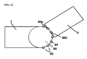
- FIG. 12 is a top plan view of a peg and slot style pivoting section, according to an embodiment.
- FIG. 13 is an exploded view of the pivoting structure, according to an embodiment.
- FIG. 14 is an elevation view of the pivoting structure, according to an embodiment.
- FIG. 15 is a cross-section view of the locking mechanism, according to an embodiment
- FIG. 16 is a bottom plan view of a pivoting delivery ramp, according to an embodiment.
- FIG. 17 is a perspective view of a safety barrier system for a pivoting delivery ramp, according to an embodiment.
- FIG. 18 is a top plan view of a pivoting delivery ramp.
- FIGS. 19 a and 19 b are cross-section views of the expanding attachment hooks in engaged and disengaged orientation respectively.
- FIG. 20 is an elevation view of the pivoting structure emphasizing truck fixture components.
- FIG. 1 shows an embodiment of a pivoting delivery ramp 1 that extends from a truck loading bed 2 to a pivot structure 3 , then to a unloading surface 6 .
- An upper ramp portion 7 and a lower ramp portion 9 couple truck loading bed 2 to the pivot structure 3 , and the pivot structure 3 to the unloading surface 6 , respectively.
- Upper ramp portion 7 couples to pivot structure 3 at a stationary segment 11 .
- Opposite stationary segment 11 of the pivot structure 3 is a rotation segment 13 to which the lower ramp portion 9 is coupled.
- Lower ramp portion 9 rests on the unloading surface 6 at the opposite end of the rotation segment 13 attachment.
- pivot structure 3 is supported by support structures 15 a - 15 d ( 15 c and 15 d not shown).
- Variable length support structures 15 a - 15 d are attached to the underside of the pivot structure 3 and extend downward to the unloading surface 6 or other supporting surface below the pivoting structure 3 .
- the variable length support structures 15 a - 15 d can accommodate various terrains inherent in unloading surface 6 as well as various support heights 17 , as shown in FIG. 2 .
- Variable length support structures 15 a and 15 c attach to stationary segment 11 and variable length support structures 15 b and 15 d attach to rotation segment 13 .
- variable length support structures 15 a - 15 d attach to rotation segment 13 and stationary segment 11 such that pivot structure 3 is supported by variable length support structures 15 a - 15 d .
- the variable length support structures 15 a - 15 d can either detach or fold flat in a compact manner when not in use, in embodiments.
- Upper ramp portion 7 also includes a truck engagement lip 20 , in embodiments as shown in FIG. 2 .
- Truck engagement lip 20 provides a graduated transition plane between upper ramp portion 7 and truck loading bed 2 as well as establishes structural fixation from upper ramp portion 7 to truck loading bed 2 .
- Truck engagement lip 20 couples to upper ramp portion 7 via lip hinge 22 , which provides angular freedom identified as truck lip angle ⁇ 1 , which represents the angle between truck engagement lip 20 and upper ramp portion 7 .
- the upper ramp portion 7 further couples to the stationary segment 11 via upper pivot hinge 24 to provide angular freedom identified as upper pivot angle ⁇ 2 , which represents the angle between upper ramp portion 7 and stationary segment 11 .
- truck lip angle ⁇ 1 and upper pivot angle ⁇ 2 are equal to each other when both truck loading bed 2 and pivot structure 3 are flat.
- the lower ramp portion 9 further couples to the rotation segment 13 via lower pivot hinge 29 to provide angular freedom identified as lower pivot angle ⁇ 3 , which represents the angle between lower ramp portion 9 and rotation segment 13 .
- Lower ramp portion 9 also includes floor lip 26 .
- Floor lip 26 similarly couples to lower ramp portion 9 via lower lip hinge 28 , which provides angular freedom identified as floor lip angle ⁇ 4 , which represents the angle between floor lip 26 and lower ramp portion 9 .
- Lip hinge 22 , pivot hinge 24 , lower lip hinge 28 , and lower pivot hinge 29 allow pivoting of delivery ramp 1 to adjust to various truck loading bed 2 heights while maintaining a desired slope at each ramp segment.
- pivot structure 3 can be advantageous for pivot structure 3 to operate on a substantially flat plane to ensure ramp stability and user safety.
- the freedom of angular motion of truck lip angle ⁇ 1 , upper pivot angle ⁇ 2 , lower pivot angle ⁇ 3 , and floor lip angle ⁇ 4 enable pivot structure 3 to operate on a generally flat plane assuming that both truck loading bed 2 and unloading surface 6 are also on a generally flat plane.
- Angle locks 30 a and 30 b shown in FIG. 1 , enable upper pivot angle ⁇ 2 to be fixed for added stability.
- angle locks 30 a and 30 b are structurally fixed to either end of stationary segment 11 .
- Angle locks 30 a and 30 b engage with upper ramp portion 7 at various locations depending on the upper pivot angle ⁇ 2 .
- Angle locks 30 c and 30 d of FIG. 1 , enable lower pivot angle ⁇ 3 to be fixed for added stability.
- Angle locks 30 c and 30 d are structurally fixed to either end of rotation segment 13 , in embodiments.
- Angle locks 30 c and 30 d engage with lower ramp portion 9 at various locations depending on the preferred lower pivot angle ⁇ 3 .
- the pivot structure 3 shown in FIG. 3 and FIG. 4 comprises the intersection of the rotation segment 13 and the stationary segment 11 .
- Stationary segment 11 includes an upper symmetric disk 40 (not shown in FIG. 3 ) and a lower symmetric disk 42 .
- the upper symmetric disk 40 and the lower symmetric disk 42 are fixed together by bolts 43 or weldment such that inner spool wall 44 is formed.
- pivot extrusion 46 of rotation segment 13 Prior to fixation of upper symmetric disk 40 and lower symmetric disk 42 , pivot extrusion 46 of rotation segment 13 is placed at the intersection of upper symmetric disk 40 and lower symmetric disk 42 such that pivot extrusion 46 is free to rotate around the inner spool wall 44 .
- stationary segment 11 Prior to fixation of upper symmetric disk 40 and lower symmetric disk 42 , stationary segment 11 is placed between upper symmetric disk 40 and the lower symmetric disk 42 and fixed together by bolts 43 or weldment. In this embodiment rotation segment 13 and stationary segment 11 concentrically rotate about each other.
- This embodiment is a simple and durable pivoting platform that is easy to manufacture and requires low maintenance.
- upper symmetric disk 40 and lower symmetric disk 42 meet to create inner bearing race 48 .
- Inner concentric wall 50 of pivot extrusion 46 then serves as outer bearing race 49 .
- the inner bearing race 48 and the inner concentric wall 50 together hold ball bearing components (not shown in this view) and therefore rotate in relation to each other.
- Bearing race 48 may also form a flat surface creating the inner drum (not shown in this view) of a plain bearing.
- rotation segment 13 and stationary segment 11 concentrically rotate about each other. This pivot structure 3 embodiment can provide easier operation due to the lowered friction forces of bearing enabled rotation.
- upper ramp portion 7 extends directly from the truck loading bed 2 to pivot structure 3 maintaining unified plane 51 .
- upper ramp portion 7 and truck engagement lip 20 are integrated into stationary segment 11 to form one rigid element.
- Unified plane 51 lies in the same plane as truck loading bed 2 .
- Lower ramp portion 9 then extends from the truck loading bed 2 directly to the unloading surface 6 within unified plane 51 .
- Variable length support structure 16 attaches to pivot structure 3 to provide cantilever support.
- two or more support structures could be used. This embodiment offers advantages relative to the dual stage pivoting ramp shown in FIG. 1 and FIG. 2 in both ease of storage and performance.
- FIG. 7 shows the same embodiment of FIG. 6 , but as shown in FIG. 7 , pivoting delivery ramp 1 is arranged in such a way that rotation segments 13 and stationary segments 11 are rotated about 110 degrees to each other.
- FIG. 7 shows the adjustability of pivoting delivery ramp 1 , and virtually any degree of rotation, in either direction, is possible.
- the systems described with respect to FIGS. 1-7 could be used to connect a variety of disassociated bases, and not just to connect a truck bed to the ground by a ramp.
- ramp systems could be used to connect loading docks, automobiles, helicopters, boats and ships, rail cars, shelving, or any other two bases or platforms that may be spaced apart vertically and/or horizontally. Such interconnections can be used for a variety of purposes, such as transporting cargo or people between any two such bases or platforms.
- the various alternatives and improvements described with respect to the following figures could also be implemented on such designs, although for convenience and clarity the bases described herein are described as truck beds. It should be understood that, with reference to all the embodiments described herein, the truck bed and/or the ground could be any of these types of base or platform.
- FIG. 8 and FIG. 9A show an embodiment of pivot structure 3 that enables rotational locking of the rotation segment 13 and stationary segment 11 .
- inner concentric wall 50 has multiple holes 54 associated with various desired lock positions.
- Upper symmetric disk 40 and lower symmetric disk 42 (not shown in FIG. 8 ) then house lock rod 52 a and lock rod 52 b and allow lock rod 52 a and lock rod 52 b to engage with the various holes of inner concentric wall 50 effectively locking pivoting delivery ramp 1 in a desired orientation.
- This locking embodiment of pivot structure 3 can provide greater structural integrity and safety while maintaining the advantageous axial rotation of non-locking embodiments of pivot structure 3 .
- FIG. 9B shows an alternative embodiment of a disc 40 ′ in which holes 54 ′ are positioned radially about the disc 40 ′.
- a similar lock rod or set of lock rods can be arranged on a stationary segment (not shown) that extend into one or more of the holes 54 ′ to prevent rotation, from a different angle than previously shown in FIG. 9A .
- This can be beneficial in embodiments where a user can reach underneath the pivoting structure and pull a pin downwards away from the disc 40 ′ to unlock and allow rotation, and release into any of the holes 54 ′ to re-lock the disc 40 ′.
- FIG. 10 shows an embodiment of the pivot structure 3 supporting structures.
- the pivot structure 3 ground support can be provided by folding cross supports 60 a and 60 b .
- Folding cross supports 60 a and 60 b attach to the underside of pivot structure 3 at support hinges 62 a and 62 b .
- Support hinges 62 a and 62 b allow folding cross supports 60 a and 60 b to lie flat against the underside of pivot structure 3 when pivoting delivery ramp 1 is not in use.
- Intersection lock 64 is a quick release fixation device that is located at the intersection of folding cross supports 60 a and 60 b . When pivoting delivery ramp 1 is in operational mode, intersection lock 64 engages with folding cross supports 60 a and 60 b and fixes them together when the desired support height 17 is reached.
- FIG. 11 shows an embodiment of pivot structure 3 where the pivoting action is accomplished by pivot plate section 70 .
- Pivot plate section 70 comprises a plurality of pivot plates 72 .
- the pivot plates 72 are sequentially connected.
- a pivot joint 74 is located at the intersection of upper ramp portion 7 and one end of the pivot plate section 70 .
- a pivot joint 74 is also located at the intersection of lower ramp portion 9 and the other end of the pivot plate section 70 , and between each pivot plate 72 within pivot plate section 70 .
- Each pivot joint 74 provides a small amount of angular motion ⁇ 5 . In sum, the angular motions ⁇ 5 create the cumulative range of motion represented by a pivoting range of motion ⁇ 6 .
- pivoting range of motion ⁇ 6 is related to the angular motion ⁇ 5 in that the pivoting range of motion ⁇ 6 is equal to 180 degrees less the summation of all angular motions ⁇ 5 present in the pivot plate section 70 .
- This pivoting section embodiment provides a less expensive alternative to other embodiments due to its simple components yet still provides rotational adjustability of other embodiments of pivot structure 3 .
- FIG. 12 shows an alternative embodiment that decouples upper ramp portion 7 and lower ramp portion 9 .
- the upper ramp portion 7 now utilizes a stationary slot deck 80 at the second end opposite the first end which engages truck delivery bed 2 .
- Stationary slot deck 80 comprises a flat platform with a circular array 82 of slots 84 that are located on the outer perimeter of stationary slot deck 80 .
- Two pegs 86 a and 86 b are located at the first end of lower ramp portion 7 .
- the space between pegs 86 a and 86 b is equal to the distance between two sequentially located slots 84 on stationary slot deck 80 .
- This embodiment of pivoting delivery ramp 1 trades the ease at which the user can rotate aforementioned embodiments of the pivoting delivery ramp 1 for a less expensive, very low maintenance version.
- one possible procedure of operation would entail the user to first set in place the upper ramp portion 7 , then move lower ramp portion 9 into the desired position. Then the user would line up pegs 86 a and 86 b of lower ramp portion 9 with two slots 84 of the circular array 82 that are associated with the desired lower ramp portion 9 position. The user can then lower pegs 86 a and 86 b into the desired two slots 84 effectively securing lower ramp portion 9 in a desired position in relation to upper ramp portion 7 .
- the pivoting structure 3 comprises four main flat segments, in the lowest cost embodiment.
- the pivot structure 3 comprises a spacer disk 90 , which is coupled to stationary segment 11 on one side and lock disc 92 the other side. Fixation can be provided by a plurality of bolts 43 coupling stationary segment 11 , spacer disc 90 , and lock disc 92 .
- Pivot opening 94 of rotation segment 13 in this embodiment, fully encapsulates spacer disc 90 and functionally rotates about spacer disk 90 providing pivoting movement of rotation segment 13 and lower ramp portion 9 with respect to stationary segment 11 and truck loading bed 2 (not shown in this embodiment).
- spacer disc 90 is designed to have a spacer thickness 96 that is always greater than rotation segment thickness 98 of rotation segment 13 to ensure that there is free movement of rotation segment 13 with respect to stationary segment 11 .
- spacer disc 90 is designed to have a spacer diameter 100 that is always less than pivot opening diameter 104 of pivot opening 94 .
- Lower ramp portion 9 attaches to rotation segment 13 via lower pivot hinge 29 .
- variable length support structure 16 can be attached to lock disc 92 , stationary segment 11 , or some other non pivoting entity of the embodiment. If attached to any pivoting entity of the embodiment, variable length support structure 16 would have a tendency to buckle when pivoting the rotation segment 13 due to transverse motion. Transverse motion due to pivoting could be accounted for, however, if distal end of variable length support structure 16 is supported by a low-friction or rolling device to interface with unloading surface 6 .
- FIG. 14 and FIG. 15 show, in greater detail, the locking mechanism 106 of the embodiment shown in FIG. 13 .
- lock shaft 108 is engaged in a desired detent 110 of lock disc 92 .
- the action of lifting the end of lower ramp portion 9 pulls lock shaft 108 out of the detent 110 , enabling rotation between stationary segment 11 and rotation segment 13 .
- connecting wire 112 transmits the rotational motion into the horizontal motion needed to actuate lock shaft 108 in and out of the detents 110 of lock disc 92 .
- connecting wire 112 may be traced through a cam system or similar in order to increase the magnitude of the horizontal motion transferred from the rotation about lower pivot hinge 29 .
- spring 114 provides continuous spring force on lock shaft 108 at lock shaft shoulder 116 in the direction in which the lock shaft 108 engages with detent 110 .
- pivotal locking is provided by a mechanism that engages and disengages by means of the user's action of lifting the lower ramp portion 9 .
- Locking mechanism 106 is advantageous in that this action is an inherent and required action already necessary in the function of pivoting delivery ramp 1 , thus providing a critical locking benefit with no extra user activity. However, if costs are prohibitive, this locking mechanism can easily be operated by hand. The locking mechanism could be fully shrouded, as shown in FIG. 16 , to protect the mechanism from the elements.
- FIG. 17 shows an embodiment of a safety barrier system 118 .
- the safety barrier system 118 includes two barrier posts 120 , which clamp directly to the side of the pivoting structure 3 and the side of the lower ramp portion 9 , respectively.
- a retractable belt 122 is secured between the two barrier posts 120 .
- the retractable belt 122 acts as a ramp path boundary to aid in keeping the user and delivery material on the ramp.
- the safety barrier system 118 could be removable to aide in compact storage.
- truck engagement lip 20 , upper ramp portion 7 or stationary segment 11 provides for direct fixation to standard hook recesses found on conventional truck loading beds.
- the truck engagement lip 20 , upper ramp portion 7 or stationary segment 11 tends to lift upward disengaging from the standard hook recesses of truck loading bed 2 . Therefore, additional fixation is needed beyond the means conventionally seen in ramp attachment hooks.
- FIG. 18 , FIG. 19 a and FIG. 19 b show one embodiment of the truck engagement lip 20 further incorporating expanding hook 130 in engaged and disengaged orientation, respectively.
- upper ramp portion 7 is eliminated in favor of a stationary segment 11 that extends directly to the truck loading bed 2 and couples to the truck via truck engagement lip 20 .
- Expanding hook 130 incorporates hook wedge 132 such that hook wedge 132 allows expanding hook 130 to freely enter a standard hook recess 134 of truck loading bed 2 . Once the expanding hook 130 enters the standard hook recess 134 and clears recess lower edge 136 , hook wedge 132 automatically expands via spring force (not shown in this embodiment). Hook wedge 132 then creates a positive mechanical stop such that expanding hook 130 cannot exit the standard hook recess 134 without disengaging mechanism (not shown in this embodiment) which overrides the aforementioned spring force and retracts hook wedge 132 .
- truck bed fastener 140 shown in FIG. 20 , accomplishes the same goal of eliminating upward disengagement of truck engagement lip 20 , stationary segment 11 , or upper ramp portion 7 .
- Truck bed fastener 140 couples, at one end, to stationary segment 11 at ramp fastener attachment point 142 located between the points where truck engagement lip 20 couples to stationary segment 11 and where variable length support structure 16 couples to stationary segment 11 .
- the ramp fastener attachment point 142 can be located such that, in operation, it provides an equal and opposite torsion moment to any torsion moment created by loading lower ramp portion 9 .
- truck fastener attachment point 144 couples to any structurally suitable point on a truck.
- Truck bed fastener 140 could be configured to couple to a conventional and standardized truck structure or, alternatively or in addition to, truck bed fastener 140 could provide for fixation to various types of attachment points on a truck.
- skid way portions of the pivoting delivery ramp 1 described herein can incorporate basic safety features of conventional loading ramps.
- the skid way is defined as any flat section of a ramp that the user directly walks on and/or moves cargo on.
- skid way portions of the pivoting delivery ramp 1 can incorporate high friction surfaces. These high friction surfaces might include a grit finish, grit paper, ribs, diamond plate, or other various anti-slip features.
- the skid ways would also have side structures, such as side ribs, to ensure that the cargo stays within the confines of the skid way and does not fall off the sides. Some embodiments can collapse and either slide into an integrated track in the truck or fit in the cargo area using as little space as possible.
Landscapes
- Engineering & Computer Science (AREA)
- Mechanical Engineering (AREA)
- Transportation (AREA)
- Auxiliary Methods And Devices For Loading And Unloading (AREA)
Abstract
Description
Claims (19)
Priority Applications (4)
| Application Number | Priority Date | Filing Date | Title |
|---|---|---|---|
| US14/990,549 US9694997B2 (en) | 2015-07-24 | 2016-01-07 | Delivery ramp with an adjustable, rotatable pivot |
| US15/747,327 US10807814B2 (en) | 2015-07-24 | 2016-07-25 | Delivery ramp with an adjustable, rotatable pivot |
| PCT/US2016/043882 WO2017019615A1 (en) | 2015-07-24 | 2016-07-25 | Delivery ramp with an adjustable, rotatable pivot |
| US16/948,490 US11820614B2 (en) | 2015-07-24 | 2020-09-21 | Delivery ramp with an adjustable, rotatable pivot |
Applications Claiming Priority (2)
| Application Number | Priority Date | Filing Date | Title |
|---|---|---|---|
| US201562196448P | 2015-07-24 | 2015-07-24 | |
| US14/990,549 US9694997B2 (en) | 2015-07-24 | 2016-01-07 | Delivery ramp with an adjustable, rotatable pivot |
Related Child Applications (2)
| Application Number | Title | Priority Date | Filing Date |
|---|---|---|---|
| PCT/US2016/043882 Continuation WO2017019615A1 (en) | 2015-07-24 | 2016-07-25 | Delivery ramp with an adjustable, rotatable pivot |
| US15/747,327 Continuation US10807814B2 (en) | 2015-07-24 | 2016-07-25 | Delivery ramp with an adjustable, rotatable pivot |
Publications (2)
| Publication Number | Publication Date |
|---|---|
| US20170022017A1 US20170022017A1 (en) | 2017-01-26 |
| US9694997B2 true US9694997B2 (en) | 2017-07-04 |
Family
ID=57836803
Family Applications (3)
| Application Number | Title | Priority Date | Filing Date |
|---|---|---|---|
| US14/990,549 Expired - Fee Related US9694997B2 (en) | 2015-07-24 | 2016-01-07 | Delivery ramp with an adjustable, rotatable pivot |
| US15/747,327 Active 2036-05-08 US10807814B2 (en) | 2015-07-24 | 2016-07-25 | Delivery ramp with an adjustable, rotatable pivot |
| US16/948,490 Active 2036-11-01 US11820614B2 (en) | 2015-07-24 | 2020-09-21 | Delivery ramp with an adjustable, rotatable pivot |
Family Applications After (2)
| Application Number | Title | Priority Date | Filing Date |
|---|---|---|---|
| US15/747,327 Active 2036-05-08 US10807814B2 (en) | 2015-07-24 | 2016-07-25 | Delivery ramp with an adjustable, rotatable pivot |
| US16/948,490 Active 2036-11-01 US11820614B2 (en) | 2015-07-24 | 2020-09-21 | Delivery ramp with an adjustable, rotatable pivot |
Country Status (2)
| Country | Link |
|---|---|
| US (3) | US9694997B2 (en) |
| WO (1) | WO2017019615A1 (en) |
Cited By (8)
| Publication number | Priority date | Publication date | Assignee | Title |
|---|---|---|---|---|
| US10172321B1 (en) * | 2017-06-13 | 2019-01-08 | Amanda Perez | Portable pet ramp |
| USD846813S1 (en) * | 2016-04-04 | 2019-04-23 | Macneil Ip Llc | Pet ramp |
| USD910938S1 (en) | 2019-03-26 | 2021-02-16 | Vermont Juvenile Furniture Mfg., Inc. | Pet ramp |
| WO2022031987A1 (en) * | 2020-08-05 | 2022-02-10 | Obrien Gene | Improved ramp assembly |
| US20220325484A1 (en) * | 2021-04-13 | 2022-10-13 | Thomas W. BATCHELDER | Portable ramp |
| US20220388779A1 (en) * | 2019-11-08 | 2022-12-08 | Leonardo S.P.A. | Closure system of the interconnection of transport units connected to each other in a convoy |
| US11585096B2 (en) | 2019-03-26 | 2023-02-21 | Vermont Juvenile Furniture Mfg., Inc. | Ultra-light freestanding pet ramp |
| US20230067153A1 (en) * | 2021-08-24 | 2023-03-02 | Zierke Innovative Industries, Llc | Platform for loading and unloading cargo from a trailer or a bed of a truck |
Families Citing this family (7)
| Publication number | Priority date | Publication date | Assignee | Title |
|---|---|---|---|---|
| CN105241671B (en) * | 2015-10-27 | 2018-01-09 | 浙江联宜电机有限公司 | Scooter climbing test bench |
| BE1024690B1 (en) * | 2016-10-24 | 2018-05-29 | Steve Florquin | Extendable bridge device and truck |
| TWI628133B (en) * | 2017-11-03 | 2018-07-01 | 東台精機股份有限公司 | Bidirectional carrying vehicle |
| CN109383579A (en) * | 2018-11-09 | 2019-02-26 | 大连君方科技有限公司 | Equipment and method for transferring goods |
| JP6892170B1 (en) * | 2020-09-11 | 2021-06-23 | 大山 章博 | Crossing board device |
| US12325602B2 (en) * | 2020-10-20 | 2025-06-10 | Chad Windsor | Truck ramp |
| FR3147158A1 (en) * | 2023-03-27 | 2024-10-04 | Psa Automobiles Sa | Articulated ramp system for utility vehicles |
Citations (26)
| Publication number | Priority date | Publication date | Assignee | Title |
|---|---|---|---|---|
| US1018407A (en) | 1908-06-26 | 1912-02-27 | John Robert Taylor | Turn-table for trolleys. |
| US3019917A (en) | 1957-06-26 | 1962-02-06 | Albert I Kegan | Mobile loading ramps |
| US3086669A (en) | 1959-12-22 | 1963-04-23 | Clark Equipment Co | Truck carrier with tilting turntable |
| US3185109A (en) | 1963-06-27 | 1965-05-25 | F F Mengel Co | Vehicle turntable |
| US4110859A (en) | 1977-11-07 | 1978-09-05 | Lichti Robert D | Passenger loading ramp |
| US4368553A (en) | 1981-04-03 | 1983-01-18 | Perry H Dwaine | Portable ramp |
| US4425069A (en) | 1981-06-12 | 1984-01-10 | Lear Siegler, Inc. | Transport for loading semitrailers and the like |
| US4796537A (en) * | 1987-11-23 | 1989-01-10 | Besser Robert G | Mobile truck turntable |
| US4813839A (en) | 1987-11-30 | 1989-03-21 | Ira Compton | Portable truck and railroad car load conveyer |
| US5004188A (en) | 1987-08-03 | 1991-04-02 | Gec Mechanical Handling Limited | Airbridge |
| JPH07251791A (en) | 1994-03-14 | 1995-10-03 | Shinkurushima Dock:Kk | Gangway device |
| US6119634A (en) | 1999-01-13 | 2000-09-19 | Myrick; Kenneth W. | Combination pet ramp and utility table |
| US6487742B1 (en) | 1999-06-10 | 2002-12-03 | Fmc Technologies, Inc. | Side pivot cab for loading or unloading an airplane |
| US6536064B1 (en) | 1999-07-06 | 2003-03-25 | Rom Corporation | Folding ramp with pivotal leg support |
| ES2208029A1 (en) | 2001-11-15 | 2004-06-01 | Anton Zenarruzabeitia Etxaniz | Gateway for ship and docking bay, comprises two sections, where former section adjacent to frame, which is associated with hinge in vertical axis in order to allow orientation of multiple sections on horizontal plane |
| US6923140B1 (en) | 2004-03-03 | 2005-08-02 | Aluminum Ladder Company | Boat access stairway |
| US7143519B2 (en) | 2004-12-30 | 2006-12-05 | Snap-On Incorporated | Alignment system with locking turntables and skid plates |
| US7367253B2 (en) | 2002-04-30 | 2008-05-06 | Credo Technology Corporation | Cutting assembly having multiple turntable locking mechanisms |
| US20090230642A1 (en) | 2008-03-17 | 2009-09-17 | Thomas James P | Hitch mounted shopping cart carrier device and methods of use therein |
| US7690878B2 (en) | 2006-02-02 | 2010-04-06 | Georgetown Rail Equipment Company | Rail car having extendable ramp being movable by a load bearing drive system |
| US7832975B1 (en) * | 2007-04-23 | 2010-11-16 | Eagle Manufacturing Company | Spring-biased folding truck ramp |
| US8196729B2 (en) | 2005-10-20 | 2012-06-12 | Kuryakyn Holdings, LLC | Portable low profile drive-over truck dump conveyor system |
| US20120204363A1 (en) | 2009-07-28 | 2012-08-16 | Tts Marine Ab | Length Changeable Ship Ramp |
| US8266750B2 (en) | 2010-03-24 | 2012-09-18 | Gatelink Aircraft Boarding Systems, Inc. | Microbridges for regional aircraft and methods of using same |
| US8413280B2 (en) | 2009-03-27 | 2013-04-09 | Hugh L. Goin | Ramp assemblies, connection devices for ramps, support structures for ramps and methods for loading and unloading a vehicle |
| US20150056049A1 (en) | 2013-08-26 | 2015-02-26 | Matthew Honigsberg | Rotatable Cargo Platform for Trailer Vehicle |
Family Cites Families (2)
| Publication number | Priority date | Publication date | Assignee | Title |
|---|---|---|---|---|
| US20100092271A1 (en) * | 2008-10-09 | 2010-04-15 | Richardson Arthur C | Revolving trailer for motorcycles |
| KR20130001841A (en) * | 2011-06-28 | 2013-01-07 | 삼성전자주식회사 | Step overpassing device for moving robot, step overpassing system for moving robot and step overpassing method for moving robot |
-
2016
- 2016-01-07 US US14/990,549 patent/US9694997B2/en not_active Expired - Fee Related
- 2016-07-25 WO PCT/US2016/043882 patent/WO2017019615A1/en not_active Ceased
- 2016-07-25 US US15/747,327 patent/US10807814B2/en active Active
-
2020
- 2020-09-21 US US16/948,490 patent/US11820614B2/en active Active
Patent Citations (28)
| Publication number | Priority date | Publication date | Assignee | Title |
|---|---|---|---|---|
| US1018407A (en) | 1908-06-26 | 1912-02-27 | John Robert Taylor | Turn-table for trolleys. |
| US3019917A (en) | 1957-06-26 | 1962-02-06 | Albert I Kegan | Mobile loading ramps |
| US3086669A (en) | 1959-12-22 | 1963-04-23 | Clark Equipment Co | Truck carrier with tilting turntable |
| US3185109A (en) | 1963-06-27 | 1965-05-25 | F F Mengel Co | Vehicle turntable |
| US4110859A (en) | 1977-11-07 | 1978-09-05 | Lichti Robert D | Passenger loading ramp |
| US4368553A (en) | 1981-04-03 | 1983-01-18 | Perry H Dwaine | Portable ramp |
| US4425069A (en) | 1981-06-12 | 1984-01-10 | Lear Siegler, Inc. | Transport for loading semitrailers and the like |
| US5004188A (en) | 1987-08-03 | 1991-04-02 | Gec Mechanical Handling Limited | Airbridge |
| US4796537A (en) * | 1987-11-23 | 1989-01-10 | Besser Robert G | Mobile truck turntable |
| US4813839A (en) | 1987-11-30 | 1989-03-21 | Ira Compton | Portable truck and railroad car load conveyer |
| JPH07251791A (en) | 1994-03-14 | 1995-10-03 | Shinkurushima Dock:Kk | Gangway device |
| US6119634A (en) | 1999-01-13 | 2000-09-19 | Myrick; Kenneth W. | Combination pet ramp and utility table |
| US6487742B1 (en) | 1999-06-10 | 2002-12-03 | Fmc Technologies, Inc. | Side pivot cab for loading or unloading an airplane |
| US6536064B1 (en) | 1999-07-06 | 2003-03-25 | Rom Corporation | Folding ramp with pivotal leg support |
| ES2208029A1 (en) | 2001-11-15 | 2004-06-01 | Anton Zenarruzabeitia Etxaniz | Gateway for ship and docking bay, comprises two sections, where former section adjacent to frame, which is associated with hinge in vertical axis in order to allow orientation of multiple sections on horizontal plane |
| US7367253B2 (en) | 2002-04-30 | 2008-05-06 | Credo Technology Corporation | Cutting assembly having multiple turntable locking mechanisms |
| US6923140B1 (en) | 2004-03-03 | 2005-08-02 | Aluminum Ladder Company | Boat access stairway |
| US7143519B2 (en) | 2004-12-30 | 2006-12-05 | Snap-On Incorporated | Alignment system with locking turntables and skid plates |
| US8196729B2 (en) | 2005-10-20 | 2012-06-12 | Kuryakyn Holdings, LLC | Portable low profile drive-over truck dump conveyor system |
| US7690878B2 (en) | 2006-02-02 | 2010-04-06 | Georgetown Rail Equipment Company | Rail car having extendable ramp being movable by a load bearing drive system |
| US7832975B1 (en) * | 2007-04-23 | 2010-11-16 | Eagle Manufacturing Company | Spring-biased folding truck ramp |
| US20090230642A1 (en) | 2008-03-17 | 2009-09-17 | Thomas James P | Hitch mounted shopping cart carrier device and methods of use therein |
| US8413280B2 (en) | 2009-03-27 | 2013-04-09 | Hugh L. Goin | Ramp assemblies, connection devices for ramps, support structures for ramps and methods for loading and unloading a vehicle |
| US8832892B2 (en) | 2009-03-27 | 2014-09-16 | Clay J. Goin | Pivot devices for ramps |
| US20120204363A1 (en) | 2009-07-28 | 2012-08-16 | Tts Marine Ab | Length Changeable Ship Ramp |
| US8402584B2 (en) | 2009-07-28 | 2013-03-26 | Tts Marine Ab | Length changeable ship ramp |
| US8266750B2 (en) | 2010-03-24 | 2012-09-18 | Gatelink Aircraft Boarding Systems, Inc. | Microbridges for regional aircraft and methods of using same |
| US20150056049A1 (en) | 2013-08-26 | 2015-02-26 | Matthew Honigsberg | Rotatable Cargo Platform for Trailer Vehicle |
Non-Patent Citations (5)
| Title |
|---|
| "Classic". Little Giant Ladder System. May 14, 2014. Retrieved on Oct. 17, 2016. https//web.archive.org/web/20150514182513/https://www.littlegiantladder.com/skin/frontend/netmedia/lgl2014/images/manuals/ladders/classic-manual.pdf>. |
| "Pivot Ramp Patent Pending". Michael Lopez Jr. Nov. 12, 2015. Retrieved from: https://web.archive.org/web/20151112234018/https://www.kickstarter.com/projects/1784801597/pivot-ramp-patent-pending>. |
| "RYR-37-22 Steel Yard Ramp" DiscountRamps.com. Aug. 22, 2014. Retrieved from: https://www.youtube.com/watch?v=-xk8qFYqNhU>. |
| "Classic". Little Giant Ladder System. May 14, 2014. Retrieved on Oct. 17, 2016. https//web.archive.org/web/20150514182513/https://www.littlegiantladder.com/skin/frontend/netmedia/lgl2014/images/manuals/ladders/classic—manual.pdf>. |
| International Search Report and Written Opinion, for PCT Application No. PCT/US2016/043882, dated Oct. 28, 2016, 22 pages. |
Cited By (15)
| Publication number | Priority date | Publication date | Assignee | Title |
|---|---|---|---|---|
| USD846813S1 (en) * | 2016-04-04 | 2019-04-23 | Macneil Ip Llc | Pet ramp |
| USD848079S1 (en) * | 2016-04-04 | 2019-05-07 | Macneil Ip Llc | Pet ramp |
| USD871682S1 (en) * | 2016-04-04 | 2019-12-31 | Macneil Ip Llc | Set of pet ramps and central pier |
| USD891002S1 (en) * | 2016-04-04 | 2020-07-21 | Macneil Ip Llc | Set of pet ramps and central pier |
| US10172321B1 (en) * | 2017-06-13 | 2019-01-08 | Amanda Perez | Portable pet ramp |
| USD911637S1 (en) | 2019-03-26 | 2021-02-23 | Vermont Juvenile Furniture Mfg., Inc. | Pet ramp |
| USD910938S1 (en) | 2019-03-26 | 2021-02-16 | Vermont Juvenile Furniture Mfg., Inc. | Pet ramp |
| US11585096B2 (en) | 2019-03-26 | 2023-02-21 | Vermont Juvenile Furniture Mfg., Inc. | Ultra-light freestanding pet ramp |
| US20220388779A1 (en) * | 2019-11-08 | 2022-12-08 | Leonardo S.P.A. | Closure system of the interconnection of transport units connected to each other in a convoy |
| US11873166B2 (en) * | 2019-11-08 | 2024-01-16 | Leonardo S.P.A. | Closure system of the interconnection of transport units connected to each other in a convoy |
| WO2022031987A1 (en) * | 2020-08-05 | 2022-02-10 | Obrien Gene | Improved ramp assembly |
| US11932157B2 (en) | 2020-08-05 | 2024-03-19 | Gene O'Brien | Ramp assembly |
| US20220325484A1 (en) * | 2021-04-13 | 2022-10-13 | Thomas W. BATCHELDER | Portable ramp |
| US20230067153A1 (en) * | 2021-08-24 | 2023-03-02 | Zierke Innovative Industries, Llc | Platform for loading and unloading cargo from a trailer or a bed of a truck |
| US12508969B2 (en) * | 2021-08-24 | 2025-12-30 | Zierke Innovative Industries, Llc | Platform for loading and unloading cargo from a trailer or a bed of a truck |
Also Published As
| Publication number | Publication date |
|---|---|
| US20210070562A1 (en) | 2021-03-11 |
| US20170022017A1 (en) | 2017-01-26 |
| US11820614B2 (en) | 2023-11-21 |
| US10807814B2 (en) | 2020-10-20 |
| US20180370744A1 (en) | 2018-12-27 |
| WO2017019615A1 (en) | 2017-02-02 |
Similar Documents
| Publication | Publication Date | Title |
|---|---|---|
| US11820614B2 (en) | Delivery ramp with an adjustable, rotatable pivot | |
| US6345950B1 (en) | Telescoping ramp comprised of modular units | |
| US9403486B2 (en) | Safety railing system and method for providing access to a tanker trailer | |
| USRE47192E1 (en) | Liftgate having a side-loadable load platform | |
| US7025174B1 (en) | Truck ladder | |
| US6378654B1 (en) | Ladder pivotally attached to a generally vertically extending surface | |
| US8584802B2 (en) | Mobile elevating work platform | |
| US9126536B2 (en) | Pivoting handrail system | |
| US8973712B2 (en) | Inground superstructure and integrated third stage arm for vehicle lift | |
| US20160075270A1 (en) | Lift gate loading ramp | |
| US9422737B2 (en) | Retractable cover | |
| US8869334B1 (en) | Mobile loading dock with load-bearing frame | |
| US10683622B2 (en) | Gangway having position locking assembly | |
| US10253464B2 (en) | Gangway having position locking assembly | |
| US8733502B2 (en) | Foldable dual track ladder system | |
| US20210355695A1 (en) | Folding hand rail and walkway | |
| US12594869B2 (en) | Ramp assembly | |
| US9428350B2 (en) | Mobile loading dock with free fall protection | |
| CA3041235C (en) | Outdoor mobile loading dock | |
| US12251971B2 (en) | Trailer support safety stand | |
| EP1697184B1 (en) | Support leg arrangement | |
| CA3041286C (en) | Solar-powered mobile loading dock | |
| US20130302121A1 (en) | Passenger Lift for Reaching Elevated Access Openings | |
| AU2009201859A1 (en) | Safety Device |
Legal Events
| Date | Code | Title | Description |
|---|---|---|---|
| STCF | Information on status: patent grant |
Free format text: PATENTED CASE |
|
| CC | Certificate of correction | ||
| FEPP | Fee payment procedure |
Free format text: MAINTENANCE FEE REMINDER MAILED (ORIGINAL EVENT CODE: REM.); ENTITY STATUS OF PATENT OWNER: MICROENTITY |
|
| LAPS | Lapse for failure to pay maintenance fees |
Free format text: PATENT EXPIRED FOR FAILURE TO PAY MAINTENANCE FEES (ORIGINAL EVENT CODE: EXP.); ENTITY STATUS OF PATENT OWNER: MICROENTITY |
|
| STCH | Information on status: patent discontinuation |
Free format text: PATENT EXPIRED DUE TO NONPAYMENT OF MAINTENANCE FEES UNDER 37 CFR 1.362 |
|
| FP | Lapsed due to failure to pay maintenance fee |
Effective date: 20210704 |
|
| FEPP | Fee payment procedure |
Free format text: SURCHARGE, PETITION TO ACCEPT PYMT AFTER EXP, UNINTENTIONAL (ORIGINAL EVENT CODE: M3558); ENTITY STATUS OF PATENT OWNER: MICROENTITY |
|
| FEPP | Fee payment procedure |
Free format text: PETITION RELATED TO MAINTENANCE FEES DISMISSED (ORIGINAL EVENT CODE: PMFS); ENTITY STATUS OF PATENT OWNER: MICROENTITY |
|
| FEPP | Fee payment procedure |
Free format text: PETITION RELATED TO MAINTENANCE FEES FILED (ORIGINAL EVENT CODE: PMFP); ENTITY STATUS OF PATENT OWNER: MICROENTITY |
|
| MAFP | Maintenance fee payment |
Free format text: PAYMENT OF MAINTENANCE FEE, 4TH YEAR, MICRO ENTITY (ORIGINAL EVENT CODE: M3551); ENTITY STATUS OF PATENT OWNER: MICROENTITY Year of fee payment: 4 |
|
| PRDP | Patent reinstated due to the acceptance of a late maintenance fee |
Effective date: 20230508 |
|
| FEPP | Fee payment procedure |
Free format text: PETITION RELATED TO MAINTENANCE FEES GRANTED (ORIGINAL EVENT CODE: PMFG); ENTITY STATUS OF PATENT OWNER: MICROENTITY |
|
| STCF | Information on status: patent grant |
Free format text: PATENTED CASE |
|
| FEPP | Fee payment procedure |
Free format text: MAINTENANCE FEE REMINDER MAILED (ORIGINAL EVENT CODE: REM.); ENTITY STATUS OF PATENT OWNER: MICROENTITY |
|
| LAPS | Lapse for failure to pay maintenance fees |
Free format text: PATENT EXPIRED FOR FAILURE TO PAY MAINTENANCE FEES (ORIGINAL EVENT CODE: EXP.); ENTITY STATUS OF PATENT OWNER: MICROENTITY |
|
| STCH | Information on status: patent discontinuation |
Free format text: PATENT EXPIRED DUE TO NONPAYMENT OF MAINTENANCE FEES UNDER 37 CFR 1.362 |
|
| FP | Lapsed due to failure to pay maintenance fee |
Effective date: 20250704 |