US9694867B2 - Locking rack system for bicycles - Google Patents
Locking rack system for bicycles Download PDFInfo
- Publication number
- US9694867B2 US9694867B2 US15/091,243 US201615091243A US9694867B2 US 9694867 B2 US9694867 B2 US 9694867B2 US 201615091243 A US201615091243 A US 201615091243A US 9694867 B2 US9694867 B2 US 9694867B2
- Authority
- US
- United States
- Prior art keywords
- rack
- receiving gap
- lid
- lever arm
- side member
- Prior art date
- Legal status (The legal status is an assumption and is not a legal conclusion. Google has not performed a legal analysis and makes no representation as to the accuracy of the status listed.)
- Active
Links
Images


Classifications
-
- B62J9/001—
-
- B—PERFORMING OPERATIONS; TRANSPORTING
- B62—LAND VEHICLES FOR TRAVELLING OTHERWISE THAN ON RAILS
- B62H—CYCLE STANDS; SUPPORTS OR HOLDERS FOR PARKING OR STORING CYCLES; APPLIANCES PREVENTING OR INDICATING UNAUTHORIZED USE OR THEFT OF CYCLES; LOCKS INTEGRAL WITH CYCLES; DEVICES FOR LEARNING TO RIDE CYCLES
- B62H5/00—Appliances preventing or indicating unauthorised use or theft of cycles; Locks integral with cycles
- B62H5/001—Preventing theft of parts or accessories used on cycles, e.g. lamp, dynamo
-
- B—PERFORMING OPERATIONS; TRANSPORTING
- B62—LAND VEHICLES FOR TRAVELLING OTHERWISE THAN ON RAILS
- B62H—CYCLE STANDS; SUPPORTS OR HOLDERS FOR PARKING OR STORING CYCLES; APPLIANCES PREVENTING OR INDICATING UNAUTHORIZED USE OR THEFT OF CYCLES; LOCKS INTEGRAL WITH CYCLES; DEVICES FOR LEARNING TO RIDE CYCLES
- B62H5/00—Appliances preventing or indicating unauthorised use or theft of cycles; Locks integral with cycles
- B62H5/003—Appliances preventing or indicating unauthorised use or theft of cycles; Locks integral with cycles using chains or cables
-
- B—PERFORMING OPERATIONS; TRANSPORTING
- B62—LAND VEHICLES FOR TRAVELLING OTHERWISE THAN ON RAILS
- B62J—CYCLE SADDLES OR SEATS; AUXILIARY DEVICES OR ACCESSORIES SPECIALLY ADAPTED TO CYCLES AND NOT OTHERWISE PROVIDED FOR, e.g. ARTICLE CARRIERS OR CYCLE PROTECTORS
- B62J6/00—Arrangement of optical signalling or lighting devices on cycles; Mounting or supporting thereof; Circuits therefor
- B62J6/20—Arrangement of reflectors, e.g. on the wheel spokes ; Lighting devices mounted on wheel spokes
-
- B—PERFORMING OPERATIONS; TRANSPORTING
- B62—LAND VEHICLES FOR TRAVELLING OTHERWISE THAN ON RAILS
- B62J—CYCLE SADDLES OR SEATS; AUXILIARY DEVICES OR ACCESSORIES SPECIALLY ADAPTED TO CYCLES AND NOT OTHERWISE PROVIDED FOR, e.g. ARTICLE CARRIERS OR CYCLE PROTECTORS
- B62J7/00—Luggage carriers
- B62J7/02—Luggage carriers characterised by the arrangement thereof on cycles
- B62J7/04—Luggage carriers characterised by the arrangement thereof on cycles arranged above or behind the rear wheel
-
- B—PERFORMING OPERATIONS; TRANSPORTING
- B62—LAND VEHICLES FOR TRAVELLING OTHERWISE THAN ON RAILS
- B62J—CYCLE SADDLES OR SEATS; AUXILIARY DEVICES OR ACCESSORIES SPECIALLY ADAPTED TO CYCLES AND NOT OTHERWISE PROVIDED FOR, e.g. ARTICLE CARRIERS OR CYCLE PROTECTORS
- B62J9/00—Containers specially adapted for cycles, e.g. panniers or saddle bags
- B62J9/20—Containers specially adapted for cycles, e.g. panniers or saddle bags attached to the cycle as accessories
- B62J9/24—Containers specially adapted for cycles, e.g. panniers or saddle bags attached to the cycle as accessories on specially adapted racks, e.g. for top or side cases
-
- B—PERFORMING OPERATIONS; TRANSPORTING
- B62—LAND VEHICLES FOR TRAVELLING OTHERWISE THAN ON RAILS
- B62J—CYCLE SADDLES OR SEATS; AUXILIARY DEVICES OR ACCESSORIES SPECIALLY ADAPTED TO CYCLES AND NOT OTHERWISE PROVIDED FOR, e.g. ARTICLE CARRIERS OR CYCLE PROTECTORS
- B62J9/00—Containers specially adapted for cycles, e.g. panniers or saddle bags
- B62J9/30—Containers specially adapted for cycles, e.g. panniers or saddle bags characterised by locking arrangements, e.g. top case locks integrated in a vehicle central locking system
-
- F—MECHANICAL ENGINEERING; LIGHTING; HEATING; WEAPONS; BLASTING
- F16—ENGINEERING ELEMENTS AND UNITS; GENERAL MEASURES FOR PRODUCING AND MAINTAINING EFFECTIVE FUNCTIONING OF MACHINES OR INSTALLATIONS; THERMAL INSULATION IN GENERAL
- F16B—DEVICES FOR FASTENING OR SECURING CONSTRUCTIONAL ELEMENTS OR MACHINE PARTS TOGETHER, e.g. NAILS, BOLTS, CIRCLIPS, CLAMPS, CLIPS OR WEDGES; JOINTS OR JOINTING
- F16B2/00—Friction-grip releasable fastenings
- F16B2/02—Clamps, i.e. with gripping action effected by positive means other than the inherent resistance to deformation of the material of the fastening
- F16B2/06—Clamps, i.e. with gripping action effected by positive means other than the inherent resistance to deformation of the material of the fastening external, i.e. with contracting action
- F16B2/10—Clamps, i.e. with gripping action effected by positive means other than the inherent resistance to deformation of the material of the fastening external, i.e. with contracting action using pivoting jaws
-
- F—MECHANICAL ENGINEERING; LIGHTING; HEATING; WEAPONS; BLASTING
- F16—ENGINEERING ELEMENTS AND UNITS; GENERAL MEASURES FOR PRODUCING AND MAINTAINING EFFECTIVE FUNCTIONING OF MACHINES OR INSTALLATIONS; THERMAL INSULATION IN GENERAL
- F16M—FRAMES, CASINGS OR BEDS OF ENGINES, MACHINES OR APPARATUS, NOT SPECIFIC TO ENGINES, MACHINES OR APPARATUS PROVIDED FOR ELSEWHERE; STANDS; SUPPORTS
- F16M13/00—Other supports for positioning apparatus or articles; Means for steadying hand-held apparatus or articles
- F16M13/02—Other supports for positioning apparatus or articles; Means for steadying hand-held apparatus or articles for supporting on, or attaching to, an object, e.g. tree, gate, window-frame, cycle
-
- B—PERFORMING OPERATIONS; TRANSPORTING
- B62—LAND VEHICLES FOR TRAVELLING OTHERWISE THAN ON RAILS
- B62K—CYCLES; CYCLE FRAMES; CYCLE STEERING DEVICES; RIDER-OPERATED TERMINAL CONTROLS SPECIALLY ADAPTED FOR CYCLES; CYCLE AXLE SUSPENSIONS; CYCLE SIDE-CARS, FORECARS, OR THE LIKE
- B62K2206/00—Quick release mechanisms adapted for cycles
Definitions
- aspects of this document related generally to the field of package and article carriers.
- embodiments are directed to a locking rack system for bicycles.
- a lockable bicycle rack system comprises a rack and a mounting clip.
- the rack comprises a body comprising a side member, a lid comprising a side member and pivotally coupled to the body between an open position and a closed position, and a locking mechanism configured to lock the lid in the closed position, the rack being configured to detachably couple to a bicycle frame.
- the mounting clip is coupled to the rack and comprises a base component adapted to couple to a container, a rack receiving gap, and a lever arm comprising a rack latch that extends at least partially across the rack receiving gap when the lever arm is in a locked position.
- the side member of the body of the rack extends through the rack receiving gap and is locked within the rack receiving gap when the rack latch is in the locked position and the side member of the lid prevents the lever arm from leaving the locked position when the lid is in the closed position.
- the mounting clip may comprise two fixed arms, each fixed arm of the two fixed arms extending away from the base component and forming the rack receiving gap between a portion of the respective fixed arm and the base component, wherein the lever arm is positioned between the two fixed arms.
- the side member of the lid may interface an outer surface of each of the two fixed arms and an outer surface of the lever arm when the lid is in the closed position to prevent the lever arm from leaving the locked position.
- the two fixed arms form only the rack receiving gap and the mounting clip is devoid of a lid receiving gap formed by an extending component.
- the rack latch may extend across at least 75% of the rack receiving gap when the lever arm is in the locked position.
- the rack latch may extend across at least 50% of the rack receiving gap when the lever arm is in the locked position.
- the lever arm may be biased to the locked position and the lever arm further comprises a grip post distal the rack latch.
- the mounting clip may comprise a plurality of mounting clips configured to couple to a channel member fixed to the container.
- a lockable bicycle rack system comprise a rack and a mounting clip.
- the rack is configured to detachably couple to a bicycle frame, and the rack comprises a first side member and a second side member movable between a first position and a second position.
- the mounting clip is coupled to the rack and comprises a base component adapted to couple to a container, a rack receiving gap, and a lever arm comprising a rack latch extending at least partially across the rack receiving gap.
- a portion of the first side member is positioned within the rack receiving gap and held within the rack receiving gap by the rack latch and the second side member prevents the rack latch from exiting the rack receiving gap when the second side member is in the first position and the allows the rack latch to exit the rack receiving gap when the second side member is in the second position.
- the rack may comprise a body comprising the first side member and a lid pivotally coupled to the body and comprising the second side member, wherein the second side member is in the first position when the lid is in a closed position and is in the second position when the lid is in an open position.
- the mounting clip may comprise a fixed arm extending away from the base component and forming the rack receiving gap between a portion of the respective fixed arm and the base component, and the second side member of the lid may interface an outer surface of the fixed arm and an outer surface of the lever arm when the lid is in the closed position to prevent the lever arm from exiting the rack receiving gap.
- the lever arm may bias the rack latch towards the base component to extend across a portion of the rack receiving gap, and wherein the lever arm further comprises a grip post distal the rack latch.
- the mounting clip may comprise a plurality of mounting clips configured to couple to a channel member fixed to the container.
- a mounting clip for coupling and locking a container to a bicycle rack comprises a base component, a fixed arm, and a lever arm.
- the base component is adapted to couple to a container.
- the fixed arm extends from the base component and forms a rack receiving gap positioned between a portion of the fixed arm and the base component, the rack receiving gap configured to receive a side member of a body of a bicycle rack.
- the lever arm is pivotally coupled to the fixed arm and comprises a rack latch, wherein the rack latch extends at least partially across the rack receiving gap when the lever arm is in a locked position and is configured to hold the side member of the body of the bicycle rack within the rack receiving gap when the lever arm is in a locked position.
- the fixed arm may comprise two fixed arms, each fixed arm of the two fixed arms extending away from the base component and forming the rack receiving gap between a portion of the respective fixed arm and the base component, wherein the lever arm is positioned between the two fixed arms.
- the lever arm may be biased to the locked position and the lever arm may further comprise a grip post distal the rack latch.
- the base component may comprise one or more through holes extending through the base component, each through hole of the one or more through holes configured to receive a screw for coupling the mounting clip to a container.
- FIG. 1 is a perspective view of a luggage rack system according to an exemplary embodiment with an integrated lock and a bag, security hooks, and pannier with a security rail and mounting clips attached;
- FIG. 2A is a perspective view of a luggage rack in an unlocked, open position with integrated lock and security hooks according to an embodiment
- FIG. 2B is a detail view of locking components of the luggage rack shown in FIG. 2A ;
- FIG. 2C is a perspective view of a luggage rack with an integrated lock in a closed, locked position according to another exemplary embodiment
- FIG. 3A is a side view of an embodiment of a rack-top bag installed on a luggage rack;
- FIG. 3B is a detail view of the rack-top bag and luggage rack shown in FIG. 3A with the rack in an open position;
- FIG. 4A is a perspective view of a first embodiment of a security clip
- FIG. 4B is a front view of a first embodiment of a security clip
- FIG. 4C is a side view of a first embodiment of a security clip
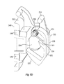
- FIG. 4D is a rear perspective view of a security clip according to an embodiment of the present disclosure.
- FIG. 5A is a perspective side view of a security clip coupling a pannier to a luggage rack
- FIG. 5B is a cross-sectional view of the security clip coupling the pannier to the luggage rack of FIG. 5A ;
- FIG. 5C is a perspective view of a second embodiment of a security clip.
- FIG. 5D is a cross-sectional view of the security clip of FIG. 5B .
- Embodiments of the present disclosure overcome the disadvantages of not being able to securely carry and store items on a bicycle by providing a locking luggage rack system.
- the system comprises luggage racks with integrated locks and spring-biased hinged components, rack-top bags, mounting clips and associated security rails, and security hooks.
- FIG. 1 shows an exemplary luggage rack system 100 comprising a rack 101 and lockable bags 120 , 148 .
- Rack 101 includes a fixed component or rack body 102 and a hinged lid 124 attached to the rack body by pivot or hinge 123 .
- Rack body 102 includes side members 103 and struts 105
- lid 124 includes side members 125 .
- the side members of each cooperate to form a fixed locking space 228 (see FIG. 2C ) between the members when the lid is closed and thus capture mounting clips there between as described below to securely lock bags carried by the rack system on the bicycle.
- lid 124 also includes an integrated lock 116 .
- Features of system 100 as described in more detail below include rack-top bag 120 , security hooks 104 , and a pannier 148 with security rails 112 , 144 , mounting clips 108 , and mounting hooks 140 attached thereto.
- Rack 101 of the luggage rack system 100 may be attached to a bicycle at an attachment point 136 or in any other suitable way.
- a reflector or light bracket 152 may be attached to the back of the luggage rack 101 .
- the pannier 148 has security rails 112 , 144 permanently affixed to a surface thereon.
- the mounting clips 108 and mounting hooks 140 are slidably adjustable within the security rails 112 , 144 until screws (not shown) passing through the mounting clips 108 and mounting hooks 140 are tightened. This slidable adjustability provides a “universal fit” in that it allows the pannier 148 to be attached to nearly any size or shape of luggage rack.
- the pannier 148 may be locked to the rack 101 by simply closing the lid 124 of the rack 101 and locking the lock 116 integrated with the rack 101 .
- the lid 124 of the rack 101 upon being closed and locked, engages the mounting clips 108 such that the mounting clips 108 , and thus the pannier 148 , cannot be removed from the rack 101 .
- side members 125 of lid 124 in cooperation with side members 103 of rack body, prevent access to screws securing mounting clips 108 to security rails 112 .
- a security cable 128 may be wrapped around a fixed object 126 (such as a tree, lamp post, or municipal bicycle rack) and attached at its ends 132 to security hooks 104 built into the luggage rack 101 .
- the lid 124 of the rack 101 upon being closed and locked, abuts or nearly abuts the security hooks 104 such that the security cable 128 cannot be removed from the security hooks 104 .
- FIG. 2A shows a luggage rack 200 with an integrated lock 208 and security hooks 204 according to an alternative embodiment.
- the luggage rack 200 may be attached to a bicycle with universal fit attachments 216 , 220 as is known in the art or in any other suitable way.
- a reflector (or tail-light or headlight) bracket 212 may be attached to the back of the luggage rack 200 .
- the lid 230 of the rack 200 is rotatable about pivot 224 and may include a latch component 234 that interfaces with the integrated lock 208 in order to lock the rack 200 in a closed position.
- a spring 226 may be provided in communication with the lid 230 such that the lid is spring-biased to close; however, in alternative embodiments, the lid 230 may be spring-biased to open.
- the luggage rack 200 may comprise elements similar to the luggage rack system 100 shown in FIG. 1 , such as but not limited to a body 202 , a side member 103 on the body 202 , and a side member 125 of the lid
- FIG. 2B shows a detail view of the luggage rack 200 shown in FIG. 2A including the lid 230 , the pivot 224 about which the lid rotates, the security hooks 204 , the integrated lock 208 , and the reflector (or tail-light or headlight) bracket 212 .
- a latching component 238 of the integrated lock 208 is additionally shown.
- the latching component 238 of the integrated lock 208 interfaces with the latch component 234 (shown in FIG. 2A ) attached to the lid 230 in order to lock the lid 230 to the rack 200 in a closed position.
- FIG. 2C shows a rear perspective view of the luggage rack 200 shown in FIG. 2A , including the lid 230 , the pivot 224 the lid rotates about, the integrated lock 208 , the reflector bracket 212 , and universal fit attachments 216 .
- the lid 230 is closed and fixed locking space 228 can be seen as formed by the spacing of rack body side member 203 and lid side member 225 in the closed and locked position.
- the lid may be locked by locking the integrated lock 208 .
- FIG. 3A shows a rack-top bag 342 installed on a luggage rack 300 according to an alternative embodiment of the present disclosure.
- the rack-top bag 342 comprises straps 346 , 348 attachable to the rack lid (see, for example, lid 330 in FIG. 3B ) in order to secure the bag 342 to the rack 300 . Also visible are the integrated lock 308 and a key 352 for operating the lock 308 .
- FIG. 3B shows a detail view of the rack-top bag 342 and luggage rack 300 shown in FIG. 3A with the rack lid 330 in an open position.
- the latch component 334 and latching component 338 are visible, as are the security hooks 304 , the key 352 , the integrated lock 308 , and the lid 330 .
- the rack-top bag 342 is secured to the lid 330 by attaching the straps 346 , 348 to the lid 330 behind the latch component 334 .
- the straps 346 , 348 are secured and locked to the lid 330 and thus to the luggage rack 300 .
- Attachment means other than straps 346 may be employed, such as connection by bolt-like members through the center plate of lid 330 or other clips, buckles, etc. wherein access to the attachment means is restricted when the lid is closed and locked.
- FIGS. 4A-D show an accessory mounting clip 400 according to an exemplary embodiment.
- Clips 400 form attachment members for attaching various accessory components, such as panniers, containers, or baskets to the rack.
- FIG. 4A shows a perspective view of the mounting clip 400 including a lever arm 425 having a grip 428 and a grip post 424 , through-holes 416 , 420 , a fixed arm 435 having an extending component 412 , a lid-receiving gap 408 , and a rack-receiving gap 404 .
- FIG. 4A shows a perspective view of the mounting clip 400 including a lever arm 425 having a grip 428 and a grip post 424 , through-holes 416 , 420 , a fixed arm 435 having an extending component 412 , a lid-receiving gap 408 , and a rack-receiving gap 404 .
- FIG. 4B shows a front view of the mounting clip 400 including the grip 428 , the grip post 424 , the through-holes 416 , 420 , the through-hole axes 432 , 434 , the extending component 412 , and the rack latch 436 .
- the positions of rack members as received in the gaps when the clip is mounted on a rack are indicated by the dashed circles in FIG. 4C .
- FIG. 4C shows a side view of the mounting clip 400 including the grip 428 , the grip post 424 , the extending component 412 , the lid-receiving gap 408 , the rack-receiving gap 404 , the rack latch 436 , and a back surface 440 .
- the side member 103 of the body 202 is positioned within the rack receiving gap 404
- the side member 125 of the lid 230 is positioned within the lid receiving gap 408 and interfacing the outer surfaces 439 , 429 of the fixed arm 435 and the lever arm 425 , respectively.
- the side member 125 of the lid 230 therefore, restricts the lever arm 425 against opening the rack receiving gap 404 .
- FIG. 4D shows a rear view of the mounting clip 400 including the grip post 424 , the extending component 412 , the lid-receiving gap 408 , the rack-receiving gap 404 , the rack latch 436 , the back surface 440 , and through-holes 444 , 446 .
- mounting clip 400 upon being inserted into a security rail 112 , is limited to a single degree of freedom (i.e., sliding back and forth along the rail 112 ) by portions of the security rail 112 that retain top and bottom portions of the mounting clip 400 .
- a mounting clip 400 may be installed on a luggage rack, such as is shown in FIG. 1 or 2 .
- force may be exerted on the grip 428 of the grip post 424 in order to cause the rack latch 436 to move in the opposite direction (since the grip post 424 and the rack latch 436 form a lever arm 425 ).
- This widens the rack-receiving gap 404 so that the mounting clip 400 may be attached to the rack by inserting a portion of the rack into the rack-receiving gap 404 .
- the mounting clip 400 may also simply be forcibly pressed onto a portion of the rack in order to force a portion of the rack into the rack-receiving gap; however, it should be noted that this may result in scratching or otherwise damaging the rack.
- screws are fitted through the through-holes 416 , 420 along the axes 432 , 434 , and through the back surface 440 of the mounting clip 400 via through-holes 444 , 446 , at which point they begin to contact and press against the security rail. Tightening the screws presses the top and bottom portions of the mounting clip 400 against the retaining portions of the security rail 112 and prevents the mounting clip 400 from being slid along the security rail 112 .
- the side members 103 , 125 of the body 202 of the rack 200 and rack lid 230 prevent access to the screws and thereby help to ensure the security of bags locked to the rack system 100 using clips 400 .
- lid 124 may be lowered such that portions of the lid 124 are inserted into lid-receiving gaps of the mounting clips 108 .
- the lid 124 is closed and the integrated lock 116 is locked, the screws (not shown) passing through the mounting clips 108 are no longer accessible, the mounting clips 108 are engaged by the lid via the lid-receiving gap, and the lid 124 substantially immobilizes the latching component of the clips 108 ; thus, the pannier 148 cannot be removed from the rack 101 .
- a rack may be fabricated from aluminum, steel, or any other suitable material.
- An integrated lock may comprise a lock-and-key, such as is shown in FIG. 3A and FIG. 3B , a combination lock, or any other suitable locking mechanism.
- a lock may be installed on the lid of the luggage rack, such as is shown in FIG. 1 , on the rack itself, as shown in, e.g., FIG. 2C , or in any other suitable location.
- Panniers may be installed on either (as shown in FIG. 1 ) or both sides of the luggage rack, and the rack may be installed on the front (in front of the front fork) or the back (behind the seat) of a bicycle.
- Mounting clips may be fabricated from plastic, nylon, or any other suitably strong, suitably pliable polymer or material.
- Security rails may be fabricated from steel, aluminum, or any other suitable material. As is well-known in the art, stronger materials can provide better security, though they may also increase cost and/or weight.
- bags used therewith may themselves be provided with locking closures. This may be accomplished, for example, by use of locking bag provided with locking closures known in the art.
- the bags may be provided with locking hasps, zipper pulls or buckles with an opening configured to receive and be secured by a strap or cable lock, such as cable lock 128 , and to be also secured by security hooks 104 in the same manner as shown for cable lock 128 in FIG. 1 .
- FIGS. 5A-5D depict various views of another non-limiting embodiment of a mounting clip 500 .
- the mounting clip 500 and rack 200 may comprise any of the features described in relation to other mounting clips or racks disclosed herein or otherwise known in the art.
- a mounting clip 500 is configured to prevent removal of the mounting clip 400 (and any container 148 coupled thereto) from the rack 200 when the lever arm 525 is in a locked position (shown in FIG. 5B ) and the lid 230 is in a closed position.
- a mounting clip 500 may be coupled to a container 148 with screws extending through the base component 502 at through holes 544 , 546 .
- a mounting clip comprises a base component 502 adapted to couple to a container 148 and/or guides 112 , a rack receiving gap 504 , and a lever arm 525 .
- a lever arm may comprise a grip post 524 and a rack latch 536 distal the grip post 524 .
- the lever arm 525 of the mounting clip shown in FIGS. 5A-D is movable between a locked position and an unlocked position.
- the rack latch 536 is sized and configured to extend at least partially across the rack receiving gap 504 when the lever arm 525 is in a locked position (shown in FIGS. 5B-D ).
- the rack latch 536 prevents the side member 103 of the body 202 of the rack 200 from exiting or slipping out of the rack receiving gap 504 .
- the rack latch 546 comprises a hook-shaped rack latch 546 wherein a side member 103 being pushed into the rack receiving gap 504 pushes the rack latch 546 sufficient to allow the side member 103 to enter the rack receiving gap 504 , but a side member being pulled outward out of the rack receiving gap 504 is blocked by the hook of the rack latch 546 .
- the rack latch 546 extends across at least 50% of the rack receiving gap 504 when in the locked position. In other embodiments, the rack latch 546 extends across at least 75% or 90% of the rack receiving gap when in the locked position. In still other embodiments, the rack latch 546 extends entirely across the rack receiving gap 504 when in the lock position.
- a lever arm 525 is biased to the locked position.
- the non-limiting embodiment depicted in FIG. 5D comprises a spring 500 coupled to the lever arm 525 and the fixed arm 535 and configured to bias the lever arm to the locked position wherein the rack latch 546 extends at least partially across the rack receiving gap 504 .
- the spring 550 may comprise a first end 551 positioned on or coupled to a tab 554 on the lever arm 525 and a second end 552 coupled to a slot 553 on the fixed arm 535 .
- the lever arm may be biased to the locked position with other biasing elements know in the art.
- FIGS. 5A and 5B depict a non-limiting embodiment of a handle release 560 .
- the handle release 560 is coupled to the lever arm 425 such that pulling the handle release 560 pulls the grip post 524 of the lever arm 525 toward the base component 502 , back surface 540 or container 148 , thus moving the rack latch 536 out of the rack receiving gap 504 sufficient to release the side member 108 from the rack receiving gap 504 .
- pulling the handle release 560 moves the lever arm 525 from the locked position to the unlocked position.
- a single handle release 560 may simultaneously move the lever arm 525 from the locked position to the unlocked position.
- a lever arm 525 may be biased such that release of the handle release 560 reverts the lever arm 525 back to the locked position.
- a mounting clip 500 comprises one or more fixed arms 535 extending away from the base component 502 .
- a mounting clip 500 comprises two fixed arms 535 with a lever arm 525 positioned between the two fixed arms 535 . Similar to the fixed arms 435 shown in FIGS. 4A-D , the fixed arms 535 of the mounting clip 500 form a downward direct rack receiving gap 504 between a portion of the fixed arms 535 and the base component 502 or back surface 540 of the mounting clip 500 .
- Mounting clip 500 may be devoid of a lid receiving gap formed by an extending component. Instead the two fixed arms 535 may form only the rack receiving gap 504 and not a lid receiving gap similar to that shown on mounting clip 400 .
- mounting clip 500 still prevent unwanted detachment of the mounting clip from the rack 200 .
- the side member 125 of the lid 230 interfaces an outer surface 539 of each of the two fixed arms 535 and an outer surface 529 of the lever arm 525 when the lid 230 is in the closed position to prevent the lever arm 525 from leaving the locked position.
- An integrated lock 208 may prevent the unwanted opening of the lid 230 from the closed position to the open position, as described elsewhere in this document.
- a locking rack may be utilized in numerous other situations where there is a need for being able to securely carry and store items, such as, but not limited to, on a motorcycle or scooter.
Landscapes
- Engineering & Computer Science (AREA)
- Mechanical Engineering (AREA)
- General Engineering & Computer Science (AREA)
- Fittings On The Vehicle Exterior For Carrying Loads, And Devices For Holding Or Mounting Articles (AREA)
Abstract
Description
Claims (20)
Priority Applications (1)
| Application Number | Priority Date | Filing Date | Title |
|---|---|---|---|
| US15/091,243 US9694867B2 (en) | 2013-03-14 | 2016-04-05 | Locking rack system for bicycles |
Applications Claiming Priority (2)
| Application Number | Priority Date | Filing Date | Title |
|---|---|---|---|
| US13/831,078 US9302725B2 (en) | 2013-03-14 | 2013-03-14 | Locking rack system for bicycles |
| US15/091,243 US9694867B2 (en) | 2013-03-14 | 2016-04-05 | Locking rack system for bicycles |
Related Parent Applications (1)
| Application Number | Title | Priority Date | Filing Date |
|---|---|---|---|
| US13/831,078 Continuation-In-Part US9302725B2 (en) | 2013-03-14 | 2013-03-14 | Locking rack system for bicycles |
Publications (2)
| Publication Number | Publication Date |
|---|---|
| US20160214669A1 US20160214669A1 (en) | 2016-07-28 |
| US9694867B2 true US9694867B2 (en) | 2017-07-04 |
Family
ID=56433197
Family Applications (1)
| Application Number | Title | Priority Date | Filing Date |
|---|---|---|---|
| US15/091,243 Active US9694867B2 (en) | 2013-03-14 | 2016-04-05 | Locking rack system for bicycles |
Country Status (1)
| Country | Link |
|---|---|
| US (1) | US9694867B2 (en) |
Cited By (2)
| Publication number | Priority date | Publication date | Assignee | Title |
|---|---|---|---|---|
| US20160369531A1 (en) * | 2015-06-19 | 2016-12-22 | ABUS August Bremicker Söhne KG | Holder |
| US20200370576A1 (en) * | 2019-05-21 | 2020-11-26 | Thule Sweden Ab | Bicycle pannier mounting arrangement |
Families Citing this family (4)
| Publication number | Priority date | Publication date | Assignee | Title |
|---|---|---|---|---|
| TWI603880B (en) * | 2017-01-18 | 2017-11-01 | Rack buckle device | |
| JP1616132S (en) * | 2017-07-28 | 2018-10-22 | ||
| CN114248862B (en) * | 2020-09-21 | 2023-04-21 | 姚新鑫 | Lockable vehicle goods shelf |
| NL2029078B1 (en) * | 2021-08-30 | 2023-03-15 | Invented Here B V | Locking assembly for a bicycle rack assembly, locking system, bicycle rack assembly, key device, and method of unlocking |
Citations (16)
| Publication number | Priority date | Publication date | Assignee | Title |
|---|---|---|---|---|
| US4966382A (en) * | 1989-05-08 | 1990-10-30 | Giles Vincent B | Bicycle accessory for carrying a shackle |
| US5435471A (en) * | 1994-05-20 | 1995-07-25 | Chuang; Louis | Article carrier for bicycle |
| US5579971A (en) * | 1995-02-07 | 1996-12-03 | Chuang; Louis | Article carrier for bicycle |
| US5836491A (en) * | 1997-09-25 | 1998-11-17 | Chuang; Louis | Lock securing device for a bicycle |
| US6095473A (en) * | 1997-05-09 | 2000-08-01 | Vaude Sport Albrecht Von Dewitz | Securing device for bags |
| US6474097B2 (en) * | 2001-01-22 | 2002-11-05 | Frank Treppedi | Compartmented mobile cooler |
| US20030106143A1 (en) * | 2000-01-10 | 2003-06-12 | Reckitt Benckiser France | Dispenser for adding a cleaning and/or deodorizing product to a toilet bowl |
| US20040211804A1 (en) * | 2003-04-24 | 2004-10-28 | Chian-Yi Lee | Holding dock structure for a steel cable shackle of bicycles |
| US20060138185A1 (en) * | 2004-12-27 | 2006-06-29 | Chien-Ping Lien | Single-piece instantly detachable locking device with a board for traveling bag on bicycle carrier |
| US20060186159A1 (en) * | 2005-02-22 | 2006-08-24 | Lawrence Carl E | Secure Cargo Carrier for a Bicycle |
| US7389608B1 (en) * | 2007-03-21 | 2008-06-24 | Mackay Michael Vincent | Fishing chest |
| US20090159626A1 (en) * | 2005-03-24 | 2009-06-25 | Hamax As | Carrier rack for a bicycle |
| US20100237208A1 (en) * | 2009-03-20 | 2010-09-23 | Stefano Di Lollo | Holder for receiving a lid or a cover |
| US8453895B2 (en) * | 2009-12-07 | 2013-06-04 | John A. Vitanza | Rear-mounted bike rack for supporting grocery bags and similar items |
| US8925752B2 (en) * | 2012-07-13 | 2015-01-06 | Gulf Coast Cooler Company, LLC | Modular cooler system |
| US20150150231A1 (en) * | 2013-12-04 | 2015-06-04 | Marcel Norman | Fishing Equipment Cooler Device |
-
2016
- 2016-04-05 US US15/091,243 patent/US9694867B2/en active Active
Patent Citations (16)
| Publication number | Priority date | Publication date | Assignee | Title |
|---|---|---|---|---|
| US4966382A (en) * | 1989-05-08 | 1990-10-30 | Giles Vincent B | Bicycle accessory for carrying a shackle |
| US5435471A (en) * | 1994-05-20 | 1995-07-25 | Chuang; Louis | Article carrier for bicycle |
| US5579971A (en) * | 1995-02-07 | 1996-12-03 | Chuang; Louis | Article carrier for bicycle |
| US6095473A (en) * | 1997-05-09 | 2000-08-01 | Vaude Sport Albrecht Von Dewitz | Securing device for bags |
| US5836491A (en) * | 1997-09-25 | 1998-11-17 | Chuang; Louis | Lock securing device for a bicycle |
| US20030106143A1 (en) * | 2000-01-10 | 2003-06-12 | Reckitt Benckiser France | Dispenser for adding a cleaning and/or deodorizing product to a toilet bowl |
| US6474097B2 (en) * | 2001-01-22 | 2002-11-05 | Frank Treppedi | Compartmented mobile cooler |
| US20040211804A1 (en) * | 2003-04-24 | 2004-10-28 | Chian-Yi Lee | Holding dock structure for a steel cable shackle of bicycles |
| US20060138185A1 (en) * | 2004-12-27 | 2006-06-29 | Chien-Ping Lien | Single-piece instantly detachable locking device with a board for traveling bag on bicycle carrier |
| US20060186159A1 (en) * | 2005-02-22 | 2006-08-24 | Lawrence Carl E | Secure Cargo Carrier for a Bicycle |
| US20090159626A1 (en) * | 2005-03-24 | 2009-06-25 | Hamax As | Carrier rack for a bicycle |
| US7389608B1 (en) * | 2007-03-21 | 2008-06-24 | Mackay Michael Vincent | Fishing chest |
| US20100237208A1 (en) * | 2009-03-20 | 2010-09-23 | Stefano Di Lollo | Holder for receiving a lid or a cover |
| US8453895B2 (en) * | 2009-12-07 | 2013-06-04 | John A. Vitanza | Rear-mounted bike rack for supporting grocery bags and similar items |
| US8925752B2 (en) * | 2012-07-13 | 2015-01-06 | Gulf Coast Cooler Company, LLC | Modular cooler system |
| US20150150231A1 (en) * | 2013-12-04 | 2015-06-04 | Marcel Norman | Fishing Equipment Cooler Device |
Cited By (5)
| Publication number | Priority date | Publication date | Assignee | Title |
|---|---|---|---|---|
| US20160369531A1 (en) * | 2015-06-19 | 2016-12-22 | ABUS August Bremicker Söhne KG | Holder |
| US10053890B2 (en) * | 2015-06-19 | 2018-08-21 | ABUS August Bremicker Söhne KG | Holder |
| US20200370576A1 (en) * | 2019-05-21 | 2020-11-26 | Thule Sweden Ab | Bicycle pannier mounting arrangement |
| US11933338B2 (en) * | 2019-05-21 | 2024-03-19 | Thule Sweden Ab | Bicycle pannier mounting arrangement |
| US12352301B2 (en) | 2019-05-21 | 2025-07-08 | Thule Sweden Ab | Bicycle pannier mounting arrangement |
Also Published As
| Publication number | Publication date |
|---|---|
| US20160214669A1 (en) | 2016-07-28 |
Similar Documents
| Publication | Publication Date | Title |
|---|---|---|
| US9302725B2 (en) | Locking rack system for bicycles | |
| US9694867B2 (en) | Locking rack system for bicycles | |
| US12545346B2 (en) | Lock mounting assemblies for transportation devices | |
| US4298151A (en) | Carrier rack | |
| US5496089A (en) | Seat post bag clip | |
| US8596506B2 (en) | Adapting apparatus for mounting an accessory equipment on a bicycle | |
| US6354476B1 (en) | Snap-on motorcycle luggage | |
| US11565631B2 (en) | Tailgate locking device and system | |
| US9173374B2 (en) | Small animal carrier for mounting on or in vehicles | |
| US20070257076A1 (en) | Cargo System Attachable to a Roof Rack | |
| US5350097A (en) | Utility rack for a vehicle | |
| US20080178642A1 (en) | Semirigid motorcycle saddlebag universal lock assemby | |
| EP0471748B1 (en) | Bicycle accessory for carrying a shackle | |
| NL2029080B1 (en) | Mounting device for a bicycle accessory, mounting system, and method of mounting | |
| US20170080872A1 (en) | Modular roof rack clamping system | |
| US20110315728A1 (en) | Concealed attachment system for motorcycle saddlebags | |
| US20130248571A1 (en) | Fastener | |
| CN1198136A (en) | container group | |
| US11613322B2 (en) | Attachment apparatus and/or system for securely attaching objects to a bicycle frame | |
| US11084547B2 (en) | Attachment apparatus and/or system for securely attaching objects to a bicycle frame | |
| WO2021094713A1 (en) | Modular carrying system | |
| US12291301B2 (en) | Container adapter plate for use with an attachment apparatus for securely attaching objects to a bicycle frame | |
| EP2117878A1 (en) | Ready-to-ride bicycle carrier | |
| US11999429B1 (en) | Apparatus for attaching a container to a two wheeled vehicle | |
| KR950007019Y1 (en) | Rear bag for the motor-cycle |
Legal Events
| Date | Code | Title | Description |
|---|---|---|---|
| AS | Assignment |
Owner name: BELL SPORTS, INC., CALIFORNIA Free format text: ASSIGNMENT OF ASSIGNORS INTEREST;ASSIGNORS:TON, TONY M.;SAMSON, ROBIN;BRODY, JOSEPH WILLIAM;REEL/FRAME:041817/0071 Effective date: 20170227 |
|
| STCF | Information on status: patent grant |
Free format text: PATENTED CASE |
|
| AS | Assignment |
Owner name: WELLS FARGO BANK, NATIONAL ASSOCIATION, AS ADMINISTRATIVE AGENT, CALIFORNIA Free format text: TERM LOAN INTELLECTUAL PROPERTY SECURITY AGREEMENT;ASSIGNORS:BEE STINGER, LLC;BELL SPORTS, INC.;BUSHNELL HOLDINGS, INC.;AND OTHERS;REEL/FRAME:047602/0001 Effective date: 20181119 Owner name: WELLS FARGO BANK, NATIONAL ASSOCIATION, AS ADMINIS Free format text: TERM LOAN INTELLECTUAL PROPERTY SECURITY AGREEMENT;ASSIGNORS:BEE STINGER, LLC;BELL SPORTS, INC.;BUSHNELL HOLDINGS, INC.;AND OTHERS;REEL/FRAME:047602/0001 Effective date: 20181119 |
|
| AS | Assignment |
Owner name: WELLS FARGO BANK, NATIONAL ASSOCIATION, AS ADMINISTRATIVE AGENT, CALIFORNIA Free format text: ABL INTELLECTUAL PROPERTY SECURITY AGREEMENT;ASSIGNORS:BEE STINGER, LLC;BELL SPORTS, INC.;BUSHNELL HOLDINGS, INC.;AND OTHERS;REEL/FRAME:047609/0001 Effective date: 20181119 Owner name: WELLS FARGO BANK, NATIONAL ASSOCIATION, AS ADMINIS Free format text: ABL INTELLECTUAL PROPERTY SECURITY AGREEMENT;ASSIGNORS:BEE STINGER, LLC;BELL SPORTS, INC.;BUSHNELL HOLDINGS, INC.;AND OTHERS;REEL/FRAME:047609/0001 Effective date: 20181119 |
|
| AS | Assignment |
Owner name: GACP FINANCE CO., LLC, CALIFORNIA Free format text: SECURITY INTEREST;ASSIGNORS:BEE STINGER LLC;BELL SPORTS, INC.;BUSHNELL HOLDINGS, INC.;AND OTHERS;REEL/FRAME:047688/0306 Effective date: 20181119 |
|
| AS | Assignment |
Owner name: C PREME LIMITED LLC, CALIFORNIA Free format text: RELEASE BY SECURED PARTY;ASSIGNOR:WELLS FARGO BANK, NATIONAL ASSOCIATION, AS ADMINISTRATIVE AGENT;REEL/FRAME:049725/0096 Effective date: 20190710 Owner name: LOGAN OUTDOOR PRODUCTS, LLC, UTAH Free format text: RELEASE BY SECURED PARTY;ASSIGNOR:WELLS FARGO BANK, NATIONAL ASSOCIATION, AS ADMINISTRATIVE AGENT;REEL/FRAME:049725/0096 Effective date: 20190710 Owner name: MILLETT INDUSTRIES, KANSAS Free format text: RELEASE BY SECURED PARTY;ASSIGNOR:WELLS FARGO BANK, NATIONAL ASSOCIATION, AS ADMINISTRATIVE AGENT;REEL/FRAME:049725/0096 Effective date: 20190710 Owner name: MICHAELS OF OREGON CO., KANSAS Free format text: RELEASE BY SECURED PARTY;ASSIGNOR:WELLS FARGO BANK, NATIONAL ASSOCIATION, AS ADMINISTRATIVE AGENT;REEL/FRAME:049725/0096 Effective date: 20190710 Owner name: BELL SPORTS, INC., CALIFORNIA Free format text: RELEASE BY SECURED PARTY;ASSIGNOR:WELLS FARGO BANK, NATIONAL ASSOCIATION, AS ADMINISTRATIVE AGENT;REEL/FRAME:049725/0096 Effective date: 20190710 Owner name: BUSHNELL INC., KANSAS Free format text: RELEASE BY SECURED PARTY;ASSIGNOR:WELLS FARGO BANK, NATIONAL ASSOCIATION, AS ADMINISTRATIVE AGENT;REEL/FRAME:049725/0096 Effective date: 20190710 Owner name: BEE STINGER, LLC, UTAH Free format text: RELEASE BY SECURED PARTY;ASSIGNOR:WELLS FARGO BANK, NATIONAL ASSOCIATION, AS ADMINISTRATIVE AGENT;REEL/FRAME:049725/0096 Effective date: 20190710 Owner name: FEDERAL CARTRIDGE COMPANY, MINNESOTA Free format text: RELEASE BY SECURED PARTY;ASSIGNOR:WELLS FARGO BANK, NATIONAL ASSOCIATION, AS ADMINISTRATIVE AGENT;REEL/FRAME:049725/0096 Effective date: 20190710 Owner name: GOLD TIP, LLC, UTAH Free format text: RELEASE BY SECURED PARTY;ASSIGNOR:WELLS FARGO BANK, NATIONAL ASSOCIATION, AS ADMINISTRATIVE AGENT;REEL/FRAME:049725/0096 Effective date: 20190710 Owner name: STONEY POINT PRODUCTS, INC., KANSAS Free format text: RELEASE BY SECURED PARTY;ASSIGNOR:WELLS FARGO BANK, NATIONAL ASSOCIATION, AS ADMINISTRATIVE AGENT;REEL/FRAME:049725/0096 Effective date: 20190710 Owner name: VISTA OUTDOOR INC., MINNESOTA Free format text: RELEASE BY SECURED PARTY;ASSIGNOR:WELLS FARGO BANK, NATIONAL ASSOCIATION, AS ADMINISTRATIVE AGENT;REEL/FRAME:049725/0096 Effective date: 20190710 Owner name: BUSHNELL HOLDINGS, INC., KANSAS Free format text: RELEASE BY SECURED PARTY;ASSIGNOR:WELLS FARGO BANK, NATIONAL ASSOCIATION, AS ADMINISTRATIVE AGENT;REEL/FRAME:049725/0096 Effective date: 20190710 Owner name: NIGHT OPTICS USA, INC., CALIFORNIA Free format text: RELEASE BY SECURED PARTY;ASSIGNOR:WELLS FARGO BANK, NATIONAL ASSOCIATION, AS ADMINISTRATIVE AGENT;REEL/FRAME:049725/0096 Effective date: 20190710 Owner name: EAGLE INDUSTRIES UNLIMITED, INC., VIRGINIA Free format text: RELEASE BY SECURED PARTY;ASSIGNOR:WELLS FARGO BANK, NATIONAL ASSOCIATION, AS ADMINISTRATIVE AGENT;REEL/FRAME:049725/0096 Effective date: 20190710 Owner name: NORTHSTAR OUTDOORS, LLC, FORMERLY KNOWN AS JIMMY S Free format text: RELEASE BY SECURED PARTY;ASSIGNOR:WELLS FARGO BANK, NATIONAL ASSOCIATION, AS ADMINISTRATIVE AGENT;REEL/FRAME:049725/0096 Effective date: 20190710 Owner name: VISTA OUTDOOR OPERATIONS LLC, MINNESOTA Free format text: RELEASE BY SECURED PARTY;ASSIGNOR:WELLS FARGO BANK, NATIONAL ASSOCIATION, AS ADMINISTRATIVE AGENT;REEL/FRAME:049725/0096 Effective date: 20190710 Owner name: CAMELBAK PRODUCTS, LLC, CALIFORNIA Free format text: RELEASE BY SECURED PARTY;ASSIGNOR:WELLS FARGO BANK, NATIONAL ASSOCIATION, AS ADMINISTRATIVE AGENT;REEL/FRAME:049725/0096 Effective date: 20190710 Owner name: NORTHSTAR OUTDOORS, LLC, FORMERLY KNOWN AS JIMMY STYKS LLC, KANSAS Free format text: RELEASE BY SECURED PARTY;ASSIGNOR:WELLS FARGO BANK, NATIONAL ASSOCIATION, AS ADMINISTRATIVE AGENT;REEL/FRAME:049725/0096 Effective date: 20190710 |
|
| AS | Assignment |
Owner name: C PREME LIMITED LLC, CALIFORNIA Free format text: RELEASE OF SECURITY AGREEMENT;ASSIGNOR:GACP FINANCE CO., LLC, AS ADMINISTRATIVE AGENT;REEL/FRAME:050827/0778 Effective date: 20191023 Owner name: EAGLE INDUSTRIES UNLIMITED, INC., VIRGINIA Free format text: RELEASE OF SECURITY AGREEMENT;ASSIGNOR:GACP FINANCE CO., LLC, AS ADMINISTRATIVE AGENT;REEL/FRAME:050827/0778 Effective date: 20191023 Owner name: STONEY POINT PRODUCTS, INC., KANSAS Free format text: RELEASE OF SECURITY AGREEMENT;ASSIGNOR:GACP FINANCE CO., LLC, AS ADMINISTRATIVE AGENT;REEL/FRAME:050827/0778 Effective date: 20191023 Owner name: MICHAELS OF OREGON CO., KANSAS Free format text: RELEASE OF SECURITY AGREEMENT;ASSIGNOR:GACP FINANCE CO., LLC, AS ADMINISTRATIVE AGENT;REEL/FRAME:050827/0778 Effective date: 20191023 Owner name: FEDERAL CARTRIDGE COMPANY, MINNESOTA Free format text: RELEASE OF SECURITY AGREEMENT;ASSIGNOR:GACP FINANCE CO., LLC, AS ADMINISTRATIVE AGENT;REEL/FRAME:050827/0778 Effective date: 20191023 Owner name: BELL SPORTS, INC., CALIFORNIA Free format text: RELEASE OF SECURITY AGREEMENT;ASSIGNOR:GACP FINANCE CO., LLC, AS ADMINISTRATIVE AGENT;REEL/FRAME:050827/0778 Effective date: 20191023 Owner name: NORTHSTAR OUTDOORS, LLC (FKA JIMMY STYKS LLC), KAN Free format text: RELEASE OF SECURITY AGREEMENT;ASSIGNOR:GACP FINANCE CO., LLC, AS ADMINISTRATIVE AGENT;REEL/FRAME:050827/0778 Effective date: 20191023 Owner name: BUSHNELL INC., KANSAS Free format text: RELEASE OF SECURITY AGREEMENT;ASSIGNOR:GACP FINANCE CO., LLC, AS ADMINISTRATIVE AGENT;REEL/FRAME:050827/0778 Effective date: 20191023 Owner name: LOGAN OUTDOOR PRODUCTS, LLC, UTAH Free format text: RELEASE OF SECURITY AGREEMENT;ASSIGNOR:GACP FINANCE CO., LLC, AS ADMINISTRATIVE AGENT;REEL/FRAME:050827/0778 Effective date: 20191023 Owner name: GOLD TIP, LLC, UTAH Free format text: RELEASE OF SECURITY AGREEMENT;ASSIGNOR:GACP FINANCE CO., LLC, AS ADMINISTRATIVE AGENT;REEL/FRAME:050827/0778 Effective date: 20191023 Owner name: BUSHNELL HOLDINGS, INC., KANSAS Free format text: RELEASE OF SECURITY AGREEMENT;ASSIGNOR:GACP FINANCE CO., LLC, AS ADMINISTRATIVE AGENT;REEL/FRAME:050827/0778 Effective date: 20191023 Owner name: VISTA OUTDOOR INC., MINNESOTA Free format text: RELEASE OF SECURITY AGREEMENT;ASSIGNOR:GACP FINANCE CO., LLC, AS ADMINISTRATIVE AGENT;REEL/FRAME:050827/0778 Effective date: 20191023 Owner name: MILLETT INDUSTRIES, KANSAS Free format text: RELEASE OF SECURITY AGREEMENT;ASSIGNOR:GACP FINANCE CO., LLC, AS ADMINISTRATIVE AGENT;REEL/FRAME:050827/0778 Effective date: 20191023 Owner name: CAMELBAK PRODUCTS, LLC, CALIFORNIA Free format text: RELEASE OF SECURITY AGREEMENT;ASSIGNOR:GACP FINANCE CO., LLC, AS ADMINISTRATIVE AGENT;REEL/FRAME:050827/0778 Effective date: 20191023 Owner name: NIGHT OPTICS USA, INC., CALIFORNIA Free format text: RELEASE OF SECURITY AGREEMENT;ASSIGNOR:GACP FINANCE CO., LLC, AS ADMINISTRATIVE AGENT;REEL/FRAME:050827/0778 Effective date: 20191023 Owner name: VISTA OUTDOOR OPERATIONS LLC, MINNESOTA Free format text: RELEASE OF SECURITY AGREEMENT;ASSIGNOR:GACP FINANCE CO., LLC, AS ADMINISTRATIVE AGENT;REEL/FRAME:050827/0778 Effective date: 20191023 Owner name: BEE STINGER, LLC, UTAH Free format text: RELEASE OF SECURITY AGREEMENT;ASSIGNOR:GACP FINANCE CO., LLC, AS ADMINISTRATIVE AGENT;REEL/FRAME:050827/0778 Effective date: 20191023 Owner name: NORTHSTAR OUTDOORS, LLC (FKA JIMMY STYKS LLC), KANSAS Free format text: RELEASE OF SECURITY AGREEMENT;ASSIGNOR:GACP FINANCE CO., LLC, AS ADMINISTRATIVE AGENT;REEL/FRAME:050827/0778 Effective date: 20191023 |
|
| MAFP | Maintenance fee payment |
Free format text: PAYMENT OF MAINTENANCE FEE, 4TH YEAR, LARGE ENTITY (ORIGINAL EVENT CODE: M1551); ENTITY STATUS OF PATENT OWNER: LARGE ENTITY Year of fee payment: 4 |
|
| AS | Assignment |
Owner name: STONEY POINT PRODUCTS, INC., KANSAS Free format text: RELEASE OF ABL INTELLECTUAL PROPERTY SECURITY AGREEMENT;ASSIGNOR:WELLS FARGO BANK, NATIONAL ASSOCIATION, AS ADMINISTRATIVE AGENT;REEL/FRAME:055796/0690 Effective date: 20210331 Owner name: FEDERAL CARTRIDGE COMPANY, MINNESOTA Free format text: RELEASE OF ABL INTELLECTUAL PROPERTY SECURITY AGREEMENT;ASSIGNOR:WELLS FARGO BANK, NATIONAL ASSOCIATION, AS ADMINISTRATIVE AGENT;REEL/FRAME:055796/0690 Effective date: 20210331 Owner name: JIMMY STYKS LLC, KANSAS Free format text: RELEASE OF ABL INTELLECTUAL PROPERTY SECURITY AGREEMENT;ASSIGNOR:WELLS FARGO BANK, NATIONAL ASSOCIATION, AS ADMINISTRATIVE AGENT;REEL/FRAME:055796/0690 Effective date: 20210331 Owner name: VISTA OUTDOOR OPERATIONS LLC/SWRI/IRA, MINNESOTA Free format text: RELEASE OF ABL INTELLECTUAL PROPERTY SECURITY AGREEMENT;ASSIGNOR:WELLS FARGO BANK, NATIONAL ASSOCIATION, AS ADMINISTRATIVE AGENT;REEL/FRAME:055796/0690 Effective date: 20210331 Owner name: EAGLE INDUSTRIES UNLIMITED, INC., VIRGINIA Free format text: RELEASE OF ABL INTELLECTUAL PROPERTY SECURITY AGREEMENT;ASSIGNOR:WELLS FARGO BANK, NATIONAL ASSOCIATION, AS ADMINISTRATIVE AGENT;REEL/FRAME:055796/0690 Effective date: 20210331 Owner name: BUSHNELL CORPORATION, KANSAS Free format text: RELEASE OF ABL INTELLECTUAL PROPERTY SECURITY AGREEMENT;ASSIGNOR:WELLS FARGO BANK, NATIONAL ASSOCIATION, AS ADMINISTRATIVE AGENT;REEL/FRAME:055796/0690 Effective date: 20210331 Owner name: VISTA OUTDOOR OPERATIONS LLC/ARMY/PPI, MINNESOTA Free format text: RELEASE OF ABL INTELLECTUAL PROPERTY SECURITY AGREEMENT;ASSIGNOR:WELLS FARGO BANK, NATIONAL ASSOCIATION, AS ADMINISTRATIVE AGENT;REEL/FRAME:055796/0690 Effective date: 20210331 Owner name: VISTA OUTDOOR OPERATIONS LLC, MINNESOTA Free format text: RELEASE OF ABL INTELLECTUAL PROPERTY SECURITY AGREEMENT;ASSIGNOR:WELLS FARGO BANK, NATIONAL ASSOCIATION, AS ADMINISTRATIVE AGENT;REEL/FRAME:055796/0690 Effective date: 20210331 Owner name: BEE STINGER, LLC, MISSISSIPPI Free format text: RELEASE OF ABL INTELLECTUAL PROPERTY SECURITY AGREEMENT;ASSIGNOR:WELLS FARGO BANK, NATIONAL ASSOCIATION, AS ADMINISTRATIVE AGENT;REEL/FRAME:055796/0690 Effective date: 20210331 Owner name: GOLD TIP, LLC, MISSISSIPPI Free format text: RELEASE OF ABL INTELLECTUAL PROPERTY SECURITY AGREEMENT;ASSIGNOR:WELLS FARGO BANK, NATIONAL ASSOCIATION, AS ADMINISTRATIVE AGENT;REEL/FRAME:055796/0690 Effective date: 20210331 Owner name: NIGHT OPTICS USA, INC., CALIFORNIA Free format text: RELEASE OF ABL INTELLECTUAL PROPERTY SECURITY AGREEMENT;ASSIGNOR:WELLS FARGO BANK, NATIONAL ASSOCIATION, AS ADMINISTRATIVE AGENT;REEL/FRAME:055796/0690 Effective date: 20210331 Owner name: MICHAELS OF OREGON CO., KANSAS Free format text: RELEASE OF ABL INTELLECTUAL PROPERTY SECURITY AGREEMENT;ASSIGNOR:WELLS FARGO BANK, NATIONAL ASSOCIATION, AS ADMINISTRATIVE AGENT;REEL/FRAME:055796/0690 Effective date: 20210331 Owner name: BELL SPORTS, INC., CALIFORNIA Free format text: RELEASE OF ABL INTELLECTUAL PROPERTY SECURITY AGREEMENT;ASSIGNOR:WELLS FARGO BANK, NATIONAL ASSOCIATION, AS ADMINISTRATIVE AGENT;REEL/FRAME:055796/0690 Effective date: 20210331 Owner name: MILLETT INDUSTRIES, KANSAS Free format text: RELEASE OF ABL INTELLECTUAL PROPERTY SECURITY AGREEMENT;ASSIGNOR:WELLS FARGO BANK, NATIONAL ASSOCIATION, AS ADMINISTRATIVE AGENT;REEL/FRAME:055796/0690 Effective date: 20210331 Owner name: BUSHNELL HOLDINGS, INC., KANSAS Free format text: RELEASE OF ABL INTELLECTUAL PROPERTY SECURITY AGREEMENT;ASSIGNOR:WELLS FARGO BANK, NATIONAL ASSOCIATION, AS ADMINISTRATIVE AGENT;REEL/FRAME:055796/0690 Effective date: 20210331 Owner name: C PREME LIMITED LLC, CALIFORNIA Free format text: RELEASE OF ABL INTELLECTUAL PROPERTY SECURITY AGREEMENT;ASSIGNOR:WELLS FARGO BANK, NATIONAL ASSOCIATION, AS ADMINISTRATIVE AGENT;REEL/FRAME:055796/0690 Effective date: 20210331 Owner name: CAMELBAK PRODUCTS, LLC, CALIFORNIA Free format text: RELEASE OF ABL INTELLECTUAL PROPERTY SECURITY AGREEMENT;ASSIGNOR:WELLS FARGO BANK, NATIONAL ASSOCIATION, AS ADMINISTRATIVE AGENT;REEL/FRAME:055796/0690 Effective date: 20210331 Owner name: BUSHNELL INC., KANSAS Free format text: RELEASE OF ABL INTELLECTUAL PROPERTY SECURITY AGREEMENT;ASSIGNOR:WELLS FARGO BANK, NATIONAL ASSOCIATION, AS ADMINISTRATIVE AGENT;REEL/FRAME:055796/0690 Effective date: 20210331 Owner name: LOGAN OUTDOOR PRODUCTS, LLC, UTAH Free format text: RELEASE OF ABL INTELLECTUAL PROPERTY SECURITY AGREEMENT;ASSIGNOR:WELLS FARGO BANK, NATIONAL ASSOCIATION, AS ADMINISTRATIVE AGENT;REEL/FRAME:055796/0690 Effective date: 20210331 Owner name: CAPITAL ONE, NATIONAL ASSOCIATION, AS ADMINISTRATIVE AGENT, MARYLAND Free format text: ABL INTELLECTUAL PROPERTY SECURITY AGREEMENT;ASSIGNORS:AMMUNITION OPERATIONS LLC;BEE STINGER, LLC;BELL SPORTS, INC.;AND OTHERS;REEL/FRAME:056033/0349 Effective date: 20210331 |
|
| AS | Assignment |
Owner name: JPMORGAN CHASE BANK, N.A., AS THE ADMINISTRATIVE AGENT, ILLINOIS Free format text: SECURITY INTEREST;ASSIGNORS:AMMUNITION OPERATIONS LLC;BEE STINGER, LLC;BELL SPORTS, INC.;AND OTHERS;REEL/FRAME:061521/0747 Effective date: 20220805 |
|
| AS | Assignment |
Owner name: SIMMS FISHING PRODUCTS LLC, MONTANA Free format text: TERMINATION AND RELEASE OF TERM LOAN INTELLECTUAL PROPERTY SECURITY AGREEMENT;ASSIGNOR:JPMORGAN CHASE BANK, N.A., AS ADMINISTRATIVE AGENT;REEL/FRAME:066959/0001 Effective date: 20240306 Owner name: FOX HEAD, INC., CALIFORNIA Free format text: TERMINATION AND RELEASE OF TERM LOAN INTELLECTUAL PROPERTY SECURITY AGREEMENT;ASSIGNOR:JPMORGAN CHASE BANK, N.A., AS ADMINISTRATIVE AGENT;REEL/FRAME:066959/0001 Effective date: 20240306 Owner name: WAWGD NEWCO, LLC, CALIFORNIA Free format text: TERMINATION AND RELEASE OF TERM LOAN INTELLECTUAL PROPERTY SECURITY AGREEMENT;ASSIGNOR:JPMORGAN CHASE BANK, N.A., AS ADMINISTRATIVE AGENT;REEL/FRAME:066959/0001 Effective date: 20240306 Owner name: VISTA OUTDOOR OPERATIONS LLC, MINNESOTA Free format text: TERMINATION AND RELEASE OF TERM LOAN INTELLECTUAL PROPERTY SECURITY AGREEMENT;ASSIGNOR:JPMORGAN CHASE BANK, N.A., AS ADMINISTRATIVE AGENT;REEL/FRAME:066959/0001 Effective date: 20240306 Owner name: STONE GLACIER, INC., MONTANA Free format text: TERMINATION AND RELEASE OF TERM LOAN INTELLECTUAL PROPERTY SECURITY AGREEMENT;ASSIGNOR:JPMORGAN CHASE BANK, N.A., AS ADMINISTRATIVE AGENT;REEL/FRAME:066959/0001 Effective date: 20240306 Owner name: MILLETT INDUSTRIES, INC., KANSAS Free format text: TERMINATION AND RELEASE OF TERM LOAN INTELLECTUAL PROPERTY SECURITY AGREEMENT;ASSIGNOR:JPMORGAN CHASE BANK, N.A., AS ADMINISTRATIVE AGENT;REEL/FRAME:066959/0001 Effective date: 20240306 Owner name: MICHAELS OF OREGON CO., KANSAS Free format text: TERMINATION AND RELEASE OF TERM LOAN INTELLECTUAL PROPERTY SECURITY AGREEMENT;ASSIGNOR:JPMORGAN CHASE BANK, N.A., AS ADMINISTRATIVE AGENT;REEL/FRAME:066959/0001 Effective date: 20240306 Owner name: LOGAN OUTDOOR PRODUCTS, LLC, UTAH Free format text: TERMINATION AND RELEASE OF TERM LOAN INTELLECTUAL PROPERTY SECURITY AGREEMENT;ASSIGNOR:JPMORGAN CHASE BANK, N.A., AS ADMINISTRATIVE AGENT;REEL/FRAME:066959/0001 Effective date: 20240306 Owner name: GOLD TIP, LLC, MISSISSIPPI Free format text: TERMINATION AND RELEASE OF TERM LOAN INTELLECTUAL PROPERTY SECURITY AGREEMENT;ASSIGNOR:JPMORGAN CHASE BANK, N.A., AS ADMINISTRATIVE AGENT;REEL/FRAME:066959/0001 Effective date: 20240306 Owner name: FEDERAL CARTRIDGE COMPANY, MINNESOTA Free format text: TERMINATION AND RELEASE OF TERM LOAN INTELLECTUAL PROPERTY SECURITY AGREEMENT;ASSIGNOR:JPMORGAN CHASE BANK, N.A., AS ADMINISTRATIVE AGENT;REEL/FRAME:066959/0001 Effective date: 20240306 Owner name: EAGLE INDUSTRIES UNLIMITED, INC., VIRGINIA Free format text: TERMINATION AND RELEASE OF TERM LOAN INTELLECTUAL PROPERTY SECURITY AGREEMENT;ASSIGNOR:JPMORGAN CHASE BANK, N.A., AS ADMINISTRATIVE AGENT;REEL/FRAME:066959/0001 Effective date: 20240306 Owner name: CAMELBAK PRODUCTS, LLC, CALIFORNIA Free format text: TERMINATION AND RELEASE OF TERM LOAN INTELLECTUAL PROPERTY SECURITY AGREEMENT;ASSIGNOR:JPMORGAN CHASE BANK, N.A., AS ADMINISTRATIVE AGENT;REEL/FRAME:066959/0001 Effective date: 20240306 Owner name: C PREME LIMITED LLC, CALIFORNIA Free format text: TERMINATION AND RELEASE OF TERM LOAN INTELLECTUAL PROPERTY SECURITY AGREEMENT;ASSIGNOR:JPMORGAN CHASE BANK, N.A., AS ADMINISTRATIVE AGENT;REEL/FRAME:066959/0001 Effective date: 20240306 Owner name: BUSHNELL INC., KANSAS Free format text: TERMINATION AND RELEASE OF TERM LOAN INTELLECTUAL PROPERTY SECURITY AGREEMENT;ASSIGNOR:JPMORGAN CHASE BANK, N.A., AS ADMINISTRATIVE AGENT;REEL/FRAME:066959/0001 Effective date: 20240306 Owner name: BUSHNELL HOLDINGS, INC., KANSAS Free format text: TERMINATION AND RELEASE OF TERM LOAN INTELLECTUAL PROPERTY SECURITY AGREEMENT;ASSIGNOR:JPMORGAN CHASE BANK, N.A., AS ADMINISTRATIVE AGENT;REEL/FRAME:066959/0001 Effective date: 20240306 Owner name: BELL SPORTS, INC., CALIFORNIA Free format text: TERMINATION AND RELEASE OF TERM LOAN INTELLECTUAL PROPERTY SECURITY AGREEMENT;ASSIGNOR:JPMORGAN CHASE BANK, N.A., AS ADMINISTRATIVE AGENT;REEL/FRAME:066959/0001 Effective date: 20240306 Owner name: AMMUNITION OPERATIONS LLC, MINNESOTA Free format text: TERMINATION AND RELEASE OF TERM LOAN INTELLECTUAL PROPERTY SECURITY AGREEMENT;ASSIGNOR:JPMORGAN CHASE BANK, N.A., AS ADMINISTRATIVE AGENT;REEL/FRAME:066959/0001 Effective date: 20240306 |
|
| AS | Assignment |
Owner name: VISTA OUTDOOR OPERATIONS LLC, MINNESOTA Free format text: RELEASE BY SECURED PARTY;ASSIGNOR:CAPITAL ONE, NATIONAL ASSOCIATION;REEL/FRAME:069460/0001 Effective date: 20241127 Owner name: STONEY POINT PRODUCTS, INC., MONTANA Free format text: RELEASE BY SECURED PARTY;ASSIGNOR:CAPITAL ONE, NATIONAL ASSOCIATION;REEL/FRAME:069460/0001 Effective date: 20241127 Owner name: MILLETT INDUSTRIES, INC., MONTANA Free format text: RELEASE BY SECURED PARTY;ASSIGNOR:CAPITAL ONE, NATIONAL ASSOCIATION;REEL/FRAME:069460/0001 Effective date: 20241127 Owner name: MICHAELS OF OREGON CO., MONTANA Free format text: RELEASE BY SECURED PARTY;ASSIGNOR:CAPITAL ONE, NATIONAL ASSOCIATION;REEL/FRAME:069460/0001 Effective date: 20241127 Owner name: LOGAN OUTDOOR PRODUCTS, LLC, UTAH Free format text: RELEASE BY SECURED PARTY;ASSIGNOR:CAPITAL ONE, NATIONAL ASSOCIATION;REEL/FRAME:069460/0001 Effective date: 20241127 Owner name: GOLD TIP, LLC, MONTANA Free format text: RELEASE BY SECURED PARTY;ASSIGNOR:CAPITAL ONE, NATIONAL ASSOCIATION;REEL/FRAME:069460/0001 Effective date: 20241127 Owner name: FEDERAL CARTRIDGE COMPANY, MINNESOTA Free format text: RELEASE BY SECURED PARTY;ASSIGNOR:CAPITAL ONE, NATIONAL ASSOCIATION;REEL/FRAME:069460/0001 Effective date: 20241127 Owner name: EAGLE INDUSTRIES UNLIMITED, INC., VIRGINIA Free format text: RELEASE BY SECURED PARTY;ASSIGNOR:CAPITAL ONE, NATIONAL ASSOCIATION;REEL/FRAME:069460/0001 Effective date: 20241127 Owner name: CAMELBAK PRODUCTS, LLC, CALIFORNIA Free format text: RELEASE BY SECURED PARTY;ASSIGNOR:CAPITAL ONE, NATIONAL ASSOCIATION;REEL/FRAME:069460/0001 Effective date: 20241127 Owner name: C PREME LIMITED LLC, CALIFORNIA Free format text: RELEASE BY SECURED PARTY;ASSIGNOR:CAPITAL ONE, NATIONAL ASSOCIATION;REEL/FRAME:069460/0001 Effective date: 20241127 Owner name: BUSHNELL HOLDINGS, INC., MONTANA Free format text: RELEASE BY SECURED PARTY;ASSIGNOR:CAPITAL ONE, NATIONAL ASSOCIATION;REEL/FRAME:069460/0001 Effective date: 20241127 Owner name: BUSHNELL INC., MONTANA Free format text: RELEASE BY SECURED PARTY;ASSIGNOR:CAPITAL ONE, NATIONAL ASSOCIATION;REEL/FRAME:069460/0001 Effective date: 20241127 Owner name: BELL SPORTS, INC., CALIFORNIA Free format text: RELEASE BY SECURED PARTY;ASSIGNOR:CAPITAL ONE, NATIONAL ASSOCIATION;REEL/FRAME:069460/0001 Effective date: 20241127 Owner name: BEE STINGER, LLC, MONTANA Free format text: RELEASE BY SECURED PARTY;ASSIGNOR:CAPITAL ONE, NATIONAL ASSOCIATION;REEL/FRAME:069460/0001 Effective date: 20241127 Owner name: AMMUNITION OPERATIONS LLC, MINNESOTA Free format text: RELEASE BY SECURED PARTY;ASSIGNOR:CAPITAL ONE, NATIONAL ASSOCIATION;REEL/FRAME:069460/0001 Effective date: 20241127 Owner name: AMMUNITION OPERATIONS LLC, MINNESOTA Free format text: RELEASE OF SECURITY INTEREST;ASSIGNOR:CAPITAL ONE, NATIONAL ASSOCIATION;REEL/FRAME:069460/0001 Effective date: 20241127 Owner name: BEE STINGER, LLC, MONTANA Free format text: RELEASE OF SECURITY INTEREST;ASSIGNOR:CAPITAL ONE, NATIONAL ASSOCIATION;REEL/FRAME:069460/0001 Effective date: 20241127 Owner name: BELL SPORTS, INC., CALIFORNIA Free format text: RELEASE OF SECURITY INTEREST;ASSIGNOR:CAPITAL ONE, NATIONAL ASSOCIATION;REEL/FRAME:069460/0001 Effective date: 20241127 Owner name: BUSHNELL INC., MONTANA Free format text: RELEASE OF SECURITY INTEREST;ASSIGNOR:CAPITAL ONE, NATIONAL ASSOCIATION;REEL/FRAME:069460/0001 Effective date: 20241127 Owner name: BUSHNELL HOLDINGS, INC., MONTANA Free format text: RELEASE OF SECURITY INTEREST;ASSIGNOR:CAPITAL ONE, NATIONAL ASSOCIATION;REEL/FRAME:069460/0001 Effective date: 20241127 Owner name: C PREME LIMITED LLC, CALIFORNIA Free format text: RELEASE OF SECURITY INTEREST;ASSIGNOR:CAPITAL ONE, NATIONAL ASSOCIATION;REEL/FRAME:069460/0001 Effective date: 20241127 Owner name: CAMELBAK PRODUCTS, LLC, CALIFORNIA Free format text: RELEASE OF SECURITY INTEREST;ASSIGNOR:CAPITAL ONE, NATIONAL ASSOCIATION;REEL/FRAME:069460/0001 Effective date: 20241127 Owner name: EAGLE INDUSTRIES UNLIMITED, INC., VIRGINIA Free format text: RELEASE OF SECURITY INTEREST;ASSIGNOR:CAPITAL ONE, NATIONAL ASSOCIATION;REEL/FRAME:069460/0001 Effective date: 20241127 Owner name: FEDERAL CARTRIDGE COMPANY, MINNESOTA Free format text: RELEASE OF SECURITY INTEREST;ASSIGNOR:CAPITAL ONE, NATIONAL ASSOCIATION;REEL/FRAME:069460/0001 Effective date: 20241127 Owner name: GOLD TIP, LLC, MONTANA Free format text: RELEASE OF SECURITY INTEREST;ASSIGNOR:CAPITAL ONE, NATIONAL ASSOCIATION;REEL/FRAME:069460/0001 Effective date: 20241127 Owner name: LOGAN OUTDOOR PRODUCTS, LLC, UTAH Free format text: RELEASE OF SECURITY INTEREST;ASSIGNOR:CAPITAL ONE, NATIONAL ASSOCIATION;REEL/FRAME:069460/0001 Effective date: 20241127 Owner name: MICHAELS OF OREGON CO., MONTANA Free format text: RELEASE OF SECURITY INTEREST;ASSIGNOR:CAPITAL ONE, NATIONAL ASSOCIATION;REEL/FRAME:069460/0001 Effective date: 20241127 Owner name: MILLETT INDUSTRIES, INC., MONTANA Free format text: RELEASE OF SECURITY INTEREST;ASSIGNOR:CAPITAL ONE, NATIONAL ASSOCIATION;REEL/FRAME:069460/0001 Effective date: 20241127 Owner name: STONEY POINT PRODUCTS, INC., MONTANA Free format text: RELEASE OF SECURITY INTEREST;ASSIGNOR:CAPITAL ONE, NATIONAL ASSOCIATION;REEL/FRAME:069460/0001 Effective date: 20241127 Owner name: VISTA OUTDOOR OPERATIONS LLC, MINNESOTA Free format text: RELEASE OF SECURITY INTEREST;ASSIGNOR:CAPITAL ONE, NATIONAL ASSOCIATION;REEL/FRAME:069460/0001 Effective date: 20241127 |
|
| AS | Assignment |
Owner name: FORTRESS CREDIT CORP., AS COLLATERAL AGENT, NEW YORK Free format text: SECURITY INTEREST;ASSIGNORS:BELL SPORTS, INC.;BUSHNELL HOLDINGS, INC.;BUSHNELL INC.;AND OTHERS;REEL/FRAME:069817/0586 Effective date: 20250103 |
|
| MAFP | Maintenance fee payment |
Free format text: PAYMENT OF MAINTENANCE FEE, 8TH YEAR, LARGE ENTITY (ORIGINAL EVENT CODE: M1552); ENTITY STATUS OF PATENT OWNER: LARGE ENTITY Year of fee payment: 8 |
|
| AS | Assignment |
Owner name: CAPITAL ONE, NATIONAL ASSOCIATION, AS THE ADMINISTRATIVE AGENT, CONNECTICUT Free format text: SECURITY INTEREST;ASSIGNORS:BELL SPORTS, INC.;BUSHNELL HOLDINGS, INC.;BUSHNELL INC.;AND OTHERS;REEL/FRAME:072238/0250 Effective date: 20250103 |
|
| AS | Assignment |
Owner name: BELL SPORTS LLC, MINNESOTA Free format text: ENTITY CONVERSION;ASSIGNOR:BELL SPORTS, INC.;REEL/FRAME:072908/0382 Effective date: 20250707 |