US9694537B2 - Bonding method and method of manufacturing microchannel device - Google Patents
Bonding method and method of manufacturing microchannel device Download PDFInfo
- Publication number
- US9694537B2 US9694537B2 US14/581,814 US201414581814A US9694537B2 US 9694537 B2 US9694537 B2 US 9694537B2 US 201414581814 A US201414581814 A US 201414581814A US 9694537 B2 US9694537 B2 US 9694537B2
- Authority
- US
- United States
- Prior art keywords
- substrate member
- protruding portion
- protruding
- welding
- value
- Prior art date
- Legal status (The legal status is an assumption and is not a legal conclusion. Google has not performed a legal analysis and makes no representation as to the accuracy of the status listed.)
- Active, expires
Links
- 238000000034 method Methods 0.000 title claims abstract description 68
- 238000004519 manufacturing process Methods 0.000 title claims description 31
- 239000000758 substrate Substances 0.000 claims abstract description 232
- 238000003466 welding Methods 0.000 claims abstract description 87
- 239000000427 antigen Substances 0.000 description 16
- 102000036639 antigens Human genes 0.000 description 16
- 108091007433 antigens Proteins 0.000 description 16
- 238000001514 detection method Methods 0.000 description 14
- 230000010355 oscillation Effects 0.000 description 13
- 239000000126 substance Substances 0.000 description 13
- 238000002372 labelling Methods 0.000 description 11
- 230000000052 comparative effect Effects 0.000 description 9
- 230000000977 initiatory effect Effects 0.000 description 8
- 239000007788 liquid Substances 0.000 description 7
- 229920005989 resin Polymers 0.000 description 7
- 239000011347 resin Substances 0.000 description 7
- 238000006243 chemical reaction Methods 0.000 description 5
- 238000005259 measurement Methods 0.000 description 5
- PCHJSUWPFVWCPO-UHFFFAOYSA-N gold Chemical compound [Au] PCHJSUWPFVWCPO-UHFFFAOYSA-N 0.000 description 3
- 239000010931 gold Substances 0.000 description 3
- 229910052737 gold Inorganic materials 0.000 description 3
- 229920005672 polyolefin resin Polymers 0.000 description 3
- 238000002203 pretreatment Methods 0.000 description 3
- 238000007789 sealing Methods 0.000 description 3
- 239000013076 target substance Substances 0.000 description 3
- 239000010409 thin film Substances 0.000 description 3
- 239000013566 allergen Substances 0.000 description 2
- 239000000463 material Substances 0.000 description 2
- 230000003287 optical effect Effects 0.000 description 2
- 229920005992 thermoplastic resin Polymers 0.000 description 2
- 239000004925 Acrylic resin Substances 0.000 description 1
- 239000004743 Polypropylene Substances 0.000 description 1
- 239000004793 Polystyrene Substances 0.000 description 1
- XUIMIQQOPSSXEZ-UHFFFAOYSA-N Silicon Chemical compound [Si] XUIMIQQOPSSXEZ-UHFFFAOYSA-N 0.000 description 1
- 239000002253 acid Substances 0.000 description 1
- 239000000853 adhesive Substances 0.000 description 1
- 230000001070 adhesive effect Effects 0.000 description 1
- 239000002390 adhesive tape Substances 0.000 description 1
- 239000003513 alkali Substances 0.000 description 1
- 238000004458 analytical method Methods 0.000 description 1
- XMQFTWRPUQYINF-UHFFFAOYSA-N bensulfuron-methyl Chemical compound COC(=O)C1=CC=CC=C1CS(=O)(=O)NC(=O)NC1=NC(OC)=CC(OC)=N1 XMQFTWRPUQYINF-UHFFFAOYSA-N 0.000 description 1
- 238000005842 biochemical reaction Methods 0.000 description 1
- 239000002981 blocking agent Substances 0.000 description 1
- 230000003247 decreasing effect Effects 0.000 description 1
- 238000006073 displacement reaction Methods 0.000 description 1
- 230000000694 effects Effects 0.000 description 1
- 238000005516 engineering process Methods 0.000 description 1
- 230000005284 excitation Effects 0.000 description 1
- 229920000747 poly(lactic acid) Polymers 0.000 description 1
- 229920003229 poly(methyl methacrylate) Polymers 0.000 description 1
- 239000004417 polycarbonate Substances 0.000 description 1
- 229920000515 polycarbonate Polymers 0.000 description 1
- 229920013716 polyethylene resin Polymers 0.000 description 1
- 239000004626 polylactic acid Substances 0.000 description 1
- 239000004926 polymethyl methacrylate Substances 0.000 description 1
- -1 polypropylene Polymers 0.000 description 1
- 229920001155 polypropylene Polymers 0.000 description 1
- 229920002223 polystyrene Polymers 0.000 description 1
- 238000003825 pressing Methods 0.000 description 1
- 102000004169 proteins and genes Human genes 0.000 description 1
- 108090000623 proteins and genes Proteins 0.000 description 1
- 239000004065 semiconductor Substances 0.000 description 1
- 229910052710 silicon Inorganic materials 0.000 description 1
- 239000010703 silicon Substances 0.000 description 1
- 238000004544 sputter deposition Methods 0.000 description 1
- 239000003381 stabilizer Substances 0.000 description 1
- 238000011144 upstream manufacturing Methods 0.000 description 1
Images


Classifications
-
- B—PERFORMING OPERATIONS; TRANSPORTING
- B29—WORKING OF PLASTICS; WORKING OF SUBSTANCES IN A PLASTIC STATE IN GENERAL
- B29C—SHAPING OR JOINING OF PLASTICS; SHAPING OF MATERIAL IN A PLASTIC STATE, NOT OTHERWISE PROVIDED FOR; AFTER-TREATMENT OF THE SHAPED PRODUCTS, e.g. REPAIRING
- B29C65/00—Joining or sealing of preformed parts, e.g. welding of plastics materials; Apparatus therefor
- B29C65/02—Joining or sealing of preformed parts, e.g. welding of plastics materials; Apparatus therefor by heating, with or without pressure
- B29C65/08—Joining or sealing of preformed parts, e.g. welding of plastics materials; Apparatus therefor by heating, with or without pressure using ultrasonic vibrations
-
- B—PERFORMING OPERATIONS; TRANSPORTING
- B01—PHYSICAL OR CHEMICAL PROCESSES OR APPARATUS IN GENERAL
- B01L—CHEMICAL OR PHYSICAL LABORATORY APPARATUS FOR GENERAL USE
- B01L3/00—Containers or dishes for laboratory use, e.g. laboratory glassware; Droppers
- B01L3/50—Containers for the purpose of retaining a material to be analysed, e.g. test tubes
- B01L3/502—Containers for the purpose of retaining a material to be analysed, e.g. test tubes with fluid transport, e.g. in multi-compartment structures
- B01L3/5027—Containers for the purpose of retaining a material to be analysed, e.g. test tubes with fluid transport, e.g. in multi-compartment structures by integrated microfluidic structures, i.e. dimensions of channels and chambers are such that surface tension forces are important, e.g. lab-on-a-chip
- B01L3/502707—Containers for the purpose of retaining a material to be analysed, e.g. test tubes with fluid transport, e.g. in multi-compartment structures by integrated microfluidic structures, i.e. dimensions of channels and chambers are such that surface tension forces are important, e.g. lab-on-a-chip characterised by the manufacture of the container or its components
-
- B—PERFORMING OPERATIONS; TRANSPORTING
- B29—WORKING OF PLASTICS; WORKING OF SUBSTANCES IN A PLASTIC STATE IN GENERAL
- B29C—SHAPING OR JOINING OF PLASTICS; SHAPING OF MATERIAL IN A PLASTIC STATE, NOT OTHERWISE PROVIDED FOR; AFTER-TREATMENT OF THE SHAPED PRODUCTS, e.g. REPAIRING
- B29C65/00—Joining or sealing of preformed parts, e.g. welding of plastics materials; Apparatus therefor
- B29C65/78—Means for handling the parts to be joined, e.g. for making containers or hollow articles, e.g. means for handling sheets, plates, web-like materials, tubular articles, hollow articles or elements to be joined therewith; Means for discharging the joined articles from the joining apparatus
- B29C65/7802—Positioning the parts to be joined, e.g. aligning, indexing or centring
- B29C65/782—Positioning the parts to be joined, e.g. aligning, indexing or centring by setting the gap between the parts to be joined
- B29C65/7823—Positioning the parts to be joined, e.g. aligning, indexing or centring by setting the gap between the parts to be joined by using distance pieces, i.e. by using spacers positioned between the parts to be joined and forming a part of the joint
- B29C65/7829—Positioning the parts to be joined, e.g. aligning, indexing or centring by setting the gap between the parts to be joined by using distance pieces, i.e. by using spacers positioned between the parts to be joined and forming a part of the joint said distance pieces being integral with at least one of the parts to be joined
-
- B—PERFORMING OPERATIONS; TRANSPORTING
- B29—WORKING OF PLASTICS; WORKING OF SUBSTANCES IN A PLASTIC STATE IN GENERAL
- B29C—SHAPING OR JOINING OF PLASTICS; SHAPING OF MATERIAL IN A PLASTIC STATE, NOT OTHERWISE PROVIDED FOR; AFTER-TREATMENT OF THE SHAPED PRODUCTS, e.g. REPAIRING
- B29C66/00—General aspects of processes or apparatus for joining preformed parts
- B29C66/01—General aspects dealing with the joint area or with the area to be joined
- B29C66/05—Particular design of joint configurations
- B29C66/10—Particular design of joint configurations particular design of the joint cross-sections
- B29C66/11—Joint cross-sections comprising a single joint-segment, i.e. one of the parts to be joined comprising a single joint-segment in the joint cross-section
- B29C66/112—Single lapped joints
- B29C66/1122—Single lap to lap joints, i.e. overlap joints
-
- B—PERFORMING OPERATIONS; TRANSPORTING
- B29—WORKING OF PLASTICS; WORKING OF SUBSTANCES IN A PLASTIC STATE IN GENERAL
- B29C—SHAPING OR JOINING OF PLASTICS; SHAPING OF MATERIAL IN A PLASTIC STATE, NOT OTHERWISE PROVIDED FOR; AFTER-TREATMENT OF THE SHAPED PRODUCTS, e.g. REPAIRING
- B29C66/00—General aspects of processes or apparatus for joining preformed parts
- B29C66/01—General aspects dealing with the joint area or with the area to be joined
- B29C66/05—Particular design of joint configurations
- B29C66/10—Particular design of joint configurations particular design of the joint cross-sections
- B29C66/11—Joint cross-sections comprising a single joint-segment, i.e. one of the parts to be joined comprising a single joint-segment in the joint cross-section
- B29C66/114—Single butt joints
-
- B—PERFORMING OPERATIONS; TRANSPORTING
- B29—WORKING OF PLASTICS; WORKING OF SUBSTANCES IN A PLASTIC STATE IN GENERAL
- B29C—SHAPING OR JOINING OF PLASTICS; SHAPING OF MATERIAL IN A PLASTIC STATE, NOT OTHERWISE PROVIDED FOR; AFTER-TREATMENT OF THE SHAPED PRODUCTS, e.g. REPAIRING
- B29C66/00—General aspects of processes or apparatus for joining preformed parts
- B29C66/01—General aspects dealing with the joint area or with the area to be joined
- B29C66/05—Particular design of joint configurations
- B29C66/20—Particular design of joint configurations particular design of the joint lines, e.g. of the weld lines
- B29C66/24—Particular design of joint configurations particular design of the joint lines, e.g. of the weld lines said joint lines being closed or non-straight
- B29C66/242—Particular design of joint configurations particular design of the joint lines, e.g. of the weld lines said joint lines being closed or non-straight said joint lines being closed, i.e. forming closed contours
-
- B—PERFORMING OPERATIONS; TRANSPORTING
- B29—WORKING OF PLASTICS; WORKING OF SUBSTANCES IN A PLASTIC STATE IN GENERAL
- B29C—SHAPING OR JOINING OF PLASTICS; SHAPING OF MATERIAL IN A PLASTIC STATE, NOT OTHERWISE PROVIDED FOR; AFTER-TREATMENT OF THE SHAPED PRODUCTS, e.g. REPAIRING
- B29C66/00—General aspects of processes or apparatus for joining preformed parts
- B29C66/01—General aspects dealing with the joint area or with the area to be joined
- B29C66/05—Particular design of joint configurations
- B29C66/302—Particular design of joint configurations the area to be joined comprising melt initiators
- B29C66/3022—Particular design of joint configurations the area to be joined comprising melt initiators said melt initiators being integral with at least one of the parts to be joined
- B29C66/30223—Particular design of joint configurations the area to be joined comprising melt initiators said melt initiators being integral with at least one of the parts to be joined said melt initiators being rib-like
-
- B—PERFORMING OPERATIONS; TRANSPORTING
- B29—WORKING OF PLASTICS; WORKING OF SUBSTANCES IN A PLASTIC STATE IN GENERAL
- B29C—SHAPING OR JOINING OF PLASTICS; SHAPING OF MATERIAL IN A PLASTIC STATE, NOT OTHERWISE PROVIDED FOR; AFTER-TREATMENT OF THE SHAPED PRODUCTS, e.g. REPAIRING
- B29C66/00—General aspects of processes or apparatus for joining preformed parts
- B29C66/50—General aspects of joining tubular articles; General aspects of joining long products, i.e. bars or profiled elements; General aspects of joining single elements to tubular articles, hollow articles or bars; General aspects of joining several hollow-preforms to form hollow or tubular articles
- B29C66/51—Joining tubular articles, profiled elements or bars; Joining single elements to tubular articles, hollow articles or bars; Joining several hollow-preforms to form hollow or tubular articles
- B29C66/53—Joining single elements to tubular articles, hollow articles or bars
- B29C66/534—Joining single elements to open ends of tubular or hollow articles or to the ends of bars
- B29C66/5346—Joining single elements to open ends of tubular or hollow articles or to the ends of bars said single elements being substantially flat
- B29C66/53461—Joining single elements to open ends of tubular or hollow articles or to the ends of bars said single elements being substantially flat joining substantially flat covers and/or substantially flat bottoms to open ends of container bodies
-
- B—PERFORMING OPERATIONS; TRANSPORTING
- B29—WORKING OF PLASTICS; WORKING OF SUBSTANCES IN A PLASTIC STATE IN GENERAL
- B29C—SHAPING OR JOINING OF PLASTICS; SHAPING OF MATERIAL IN A PLASTIC STATE, NOT OTHERWISE PROVIDED FOR; AFTER-TREATMENT OF THE SHAPED PRODUCTS, e.g. REPAIRING
- B29C66/00—General aspects of processes or apparatus for joining preformed parts
- B29C66/70—General aspects of processes or apparatus for joining preformed parts characterised by the composition, physical properties or the structure of the material of the parts to be joined; Joining with non-plastics material
- B29C66/73—General aspects of processes or apparatus for joining preformed parts characterised by the composition, physical properties or the structure of the material of the parts to be joined; Joining with non-plastics material characterised by the intensive physical properties of the material of the parts to be joined, by the optical properties of the material of the parts to be joined, by the extensive physical properties of the parts to be joined, by the state of the material of the parts to be joined or by the material of the parts to be joined being a thermoplastic or a thermoset
- B29C66/733—General aspects of processes or apparatus for joining preformed parts characterised by the composition, physical properties or the structure of the material of the parts to be joined; Joining with non-plastics material characterised by the intensive physical properties of the material of the parts to be joined, by the optical properties of the material of the parts to be joined, by the extensive physical properties of the parts to be joined, by the state of the material of the parts to be joined or by the material of the parts to be joined being a thermoplastic or a thermoset characterised by the optical properties of the material of the parts to be joined, e.g. fluorescence, phosphorescence
- B29C66/7336—General aspects of processes or apparatus for joining preformed parts characterised by the composition, physical properties or the structure of the material of the parts to be joined; Joining with non-plastics material characterised by the intensive physical properties of the material of the parts to be joined, by the optical properties of the material of the parts to be joined, by the extensive physical properties of the parts to be joined, by the state of the material of the parts to be joined or by the material of the parts to be joined being a thermoplastic or a thermoset characterised by the optical properties of the material of the parts to be joined, e.g. fluorescence, phosphorescence at least one of the parts to be joined being opaque, transparent or translucent to visible light
- B29C66/73365—General aspects of processes or apparatus for joining preformed parts characterised by the composition, physical properties or the structure of the material of the parts to be joined; Joining with non-plastics material characterised by the intensive physical properties of the material of the parts to be joined, by the optical properties of the material of the parts to be joined, by the extensive physical properties of the parts to be joined, by the state of the material of the parts to be joined or by the material of the parts to be joined being a thermoplastic or a thermoset characterised by the optical properties of the material of the parts to be joined, e.g. fluorescence, phosphorescence at least one of the parts to be joined being opaque, transparent or translucent to visible light at least one of the parts to be joined being transparent or translucent to visible light
-
- B—PERFORMING OPERATIONS; TRANSPORTING
- B29—WORKING OF PLASTICS; WORKING OF SUBSTANCES IN A PLASTIC STATE IN GENERAL
- B29C—SHAPING OR JOINING OF PLASTICS; SHAPING OF MATERIAL IN A PLASTIC STATE, NOT OTHERWISE PROVIDED FOR; AFTER-TREATMENT OF THE SHAPED PRODUCTS, e.g. REPAIRING
- B29C66/00—General aspects of processes or apparatus for joining preformed parts
- B29C66/80—General aspects of machine operations or constructions and parts thereof
- B29C66/83—General aspects of machine operations or constructions and parts thereof characterised by the movement of the joining or pressing tools
- B29C66/832—Reciprocating joining or pressing tools
- B29C66/8322—Joining or pressing tools reciprocating along one axis
-
- B—PERFORMING OPERATIONS; TRANSPORTING
- B29—WORKING OF PLASTICS; WORKING OF SUBSTANCES IN A PLASTIC STATE IN GENERAL
- B29C—SHAPING OR JOINING OF PLASTICS; SHAPING OF MATERIAL IN A PLASTIC STATE, NOT OTHERWISE PROVIDED FOR; AFTER-TREATMENT OF THE SHAPED PRODUCTS, e.g. REPAIRING
- B29C66/00—General aspects of processes or apparatus for joining preformed parts
- B29C66/90—Measuring or controlling the joining process
- B29C66/94—Measuring or controlling the joining process by measuring or controlling the time
- B29C66/942—Measuring or controlling the joining process by measuring or controlling the time by measuring the time
-
- B—PERFORMING OPERATIONS; TRANSPORTING
- B29—WORKING OF PLASTICS; WORKING OF SUBSTANCES IN A PLASTIC STATE IN GENERAL
- B29C—SHAPING OR JOINING OF PLASTICS; SHAPING OF MATERIAL IN A PLASTIC STATE, NOT OTHERWISE PROVIDED FOR; AFTER-TREATMENT OF THE SHAPED PRODUCTS, e.g. REPAIRING
- B29C66/00—General aspects of processes or apparatus for joining preformed parts
- B29C66/90—Measuring or controlling the joining process
- B29C66/94—Measuring or controlling the joining process by measuring or controlling the time
- B29C66/944—Measuring or controlling the joining process by measuring or controlling the time by controlling or regulating the time
-
- B—PERFORMING OPERATIONS; TRANSPORTING
- B29—WORKING OF PLASTICS; WORKING OF SUBSTANCES IN A PLASTIC STATE IN GENERAL
- B29C—SHAPING OR JOINING OF PLASTICS; SHAPING OF MATERIAL IN A PLASTIC STATE, NOT OTHERWISE PROVIDED FOR; AFTER-TREATMENT OF THE SHAPED PRODUCTS, e.g. REPAIRING
- B29C66/00—General aspects of processes or apparatus for joining preformed parts
- B29C66/90—Measuring or controlling the joining process
- B29C66/94—Measuring or controlling the joining process by measuring or controlling the time
- B29C66/949—Measuring or controlling the joining process by measuring or controlling the time characterised by specific time values or ranges
- B29C66/9492—Measuring or controlling the joining process by measuring or controlling the time characterised by specific time values or ranges in explicit relation to another variable
-
- B—PERFORMING OPERATIONS; TRANSPORTING
- B29—WORKING OF PLASTICS; WORKING OF SUBSTANCES IN A PLASTIC STATE IN GENERAL
- B29C—SHAPING OR JOINING OF PLASTICS; SHAPING OF MATERIAL IN A PLASTIC STATE, NOT OTHERWISE PROVIDED FOR; AFTER-TREATMENT OF THE SHAPED PRODUCTS, e.g. REPAIRING
- B29C66/00—General aspects of processes or apparatus for joining preformed parts
- B29C66/90—Measuring or controlling the joining process
- B29C66/95—Measuring or controlling the joining process by measuring or controlling specific variables not covered by groups B29C66/91 - B29C66/94
- B29C66/951—Measuring or controlling the joining process by measuring or controlling specific variables not covered by groups B29C66/91 - B29C66/94 by measuring or controlling the vibration frequency and/or the vibration amplitude of vibrating joining tools, e.g. of ultrasonic welding tools
- B29C66/9516—Measuring or controlling the joining process by measuring or controlling specific variables not covered by groups B29C66/91 - B29C66/94 by measuring or controlling the vibration frequency and/or the vibration amplitude of vibrating joining tools, e.g. of ultrasonic welding tools by controlling their vibration amplitude
-
- B—PERFORMING OPERATIONS; TRANSPORTING
- B29—WORKING OF PLASTICS; WORKING OF SUBSTANCES IN A PLASTIC STATE IN GENERAL
- B29C—SHAPING OR JOINING OF PLASTICS; SHAPING OF MATERIAL IN A PLASTIC STATE, NOT OTHERWISE PROVIDED FOR; AFTER-TREATMENT OF THE SHAPED PRODUCTS, e.g. REPAIRING
- B29C66/00—General aspects of processes or apparatus for joining preformed parts
- B29C66/90—Measuring or controlling the joining process
- B29C66/95—Measuring or controlling the joining process by measuring or controlling specific variables not covered by groups B29C66/91 - B29C66/94
- B29C66/951—Measuring or controlling the joining process by measuring or controlling specific variables not covered by groups B29C66/91 - B29C66/94 by measuring or controlling the vibration frequency and/or the vibration amplitude of vibrating joining tools, e.g. of ultrasonic welding tools
- B29C66/9517—Measuring or controlling the joining process by measuring or controlling specific variables not covered by groups B29C66/91 - B29C66/94 by measuring or controlling the vibration frequency and/or the vibration amplitude of vibrating joining tools, e.g. of ultrasonic welding tools characterised by specific vibration amplitude values or ranges
-
- B—PERFORMING OPERATIONS; TRANSPORTING
- B81—MICROSTRUCTURAL TECHNOLOGY
- B81C—PROCESSES OR APPARATUS SPECIALLY ADAPTED FOR THE MANUFACTURE OR TREATMENT OF MICROSTRUCTURAL DEVICES OR SYSTEMS
- B81C3/00—Assembling of devices or systems from individually processed components
- B81C3/001—Bonding of two components
-
- B—PERFORMING OPERATIONS; TRANSPORTING
- B01—PHYSICAL OR CHEMICAL PROCESSES OR APPARATUS IN GENERAL
- B01L—CHEMICAL OR PHYSICAL LABORATORY APPARATUS FOR GENERAL USE
- B01L2200/00—Solutions for specific problems relating to chemical or physical laboratory apparatus
- B01L2200/06—Fluid handling related problems
- B01L2200/0689—Sealing
-
- B—PERFORMING OPERATIONS; TRANSPORTING
- B01—PHYSICAL OR CHEMICAL PROCESSES OR APPARATUS IN GENERAL
- B01L—CHEMICAL OR PHYSICAL LABORATORY APPARATUS FOR GENERAL USE
- B01L2300/00—Additional constructional details
- B01L2300/08—Geometry, shape and general structure
- B01L2300/0809—Geometry, shape and general structure rectangular shaped
- B01L2300/0816—Cards, e.g. flat sample carriers usually with flow in two horizontal directions
-
- B—PERFORMING OPERATIONS; TRANSPORTING
- B01—PHYSICAL OR CHEMICAL PROCESSES OR APPARATUS IN GENERAL
- B01L—CHEMICAL OR PHYSICAL LABORATORY APPARATUS FOR GENERAL USE
- B01L2300/00—Additional constructional details
- B01L2300/08—Geometry, shape and general structure
- B01L2300/0887—Laminated structure
-
- B—PERFORMING OPERATIONS; TRANSPORTING
- B29—WORKING OF PLASTICS; WORKING OF SUBSTANCES IN A PLASTIC STATE IN GENERAL
- B29C—SHAPING OR JOINING OF PLASTICS; SHAPING OF MATERIAL IN A PLASTIC STATE, NOT OTHERWISE PROVIDED FOR; AFTER-TREATMENT OF THE SHAPED PRODUCTS, e.g. REPAIRING
- B29C66/00—General aspects of processes or apparatus for joining preformed parts
- B29C66/50—General aspects of joining tubular articles; General aspects of joining long products, i.e. bars or profiled elements; General aspects of joining single elements to tubular articles, hollow articles or bars; General aspects of joining several hollow-preforms to form hollow or tubular articles
- B29C66/61—Joining from or joining on the inside
-
- B—PERFORMING OPERATIONS; TRANSPORTING
- B29—WORKING OF PLASTICS; WORKING OF SUBSTANCES IN A PLASTIC STATE IN GENERAL
- B29C—SHAPING OR JOINING OF PLASTICS; SHAPING OF MATERIAL IN A PLASTIC STATE, NOT OTHERWISE PROVIDED FOR; AFTER-TREATMENT OF THE SHAPED PRODUCTS, e.g. REPAIRING
- B29C66/00—General aspects of processes or apparatus for joining preformed parts
- B29C66/70—General aspects of processes or apparatus for joining preformed parts characterised by the composition, physical properties or the structure of the material of the parts to be joined; Joining with non-plastics material
- B29C66/71—General aspects of processes or apparatus for joining preformed parts characterised by the composition, physical properties or the structure of the material of the parts to be joined; Joining with non-plastics material characterised by the composition of the plastics material of the parts to be joined
-
- B—PERFORMING OPERATIONS; TRANSPORTING
- B29—WORKING OF PLASTICS; WORKING OF SUBSTANCES IN A PLASTIC STATE IN GENERAL
- B29C—SHAPING OR JOINING OF PLASTICS; SHAPING OF MATERIAL IN A PLASTIC STATE, NOT OTHERWISE PROVIDED FOR; AFTER-TREATMENT OF THE SHAPED PRODUCTS, e.g. REPAIRING
- B29C66/00—General aspects of processes or apparatus for joining preformed parts
- B29C66/70—General aspects of processes or apparatus for joining preformed parts characterised by the composition, physical properties or the structure of the material of the parts to be joined; Joining with non-plastics material
- B29C66/73—General aspects of processes or apparatus for joining preformed parts characterised by the composition, physical properties or the structure of the material of the parts to be joined; Joining with non-plastics material characterised by the intensive physical properties of the material of the parts to be joined, by the optical properties of the material of the parts to be joined, by the extensive physical properties of the parts to be joined, by the state of the material of the parts to be joined or by the material of the parts to be joined being a thermoplastic or a thermoset
- B29C66/733—General aspects of processes or apparatus for joining preformed parts characterised by the composition, physical properties or the structure of the material of the parts to be joined; Joining with non-plastics material characterised by the intensive physical properties of the material of the parts to be joined, by the optical properties of the material of the parts to be joined, by the extensive physical properties of the parts to be joined, by the state of the material of the parts to be joined or by the material of the parts to be joined being a thermoplastic or a thermoset characterised by the optical properties of the material of the parts to be joined, e.g. fluorescence, phosphorescence
- B29C66/7336—General aspects of processes or apparatus for joining preformed parts characterised by the composition, physical properties or the structure of the material of the parts to be joined; Joining with non-plastics material characterised by the intensive physical properties of the material of the parts to be joined, by the optical properties of the material of the parts to be joined, by the extensive physical properties of the parts to be joined, by the state of the material of the parts to be joined or by the material of the parts to be joined being a thermoplastic or a thermoset characterised by the optical properties of the material of the parts to be joined, e.g. fluorescence, phosphorescence at least one of the parts to be joined being opaque, transparent or translucent to visible light
- B29C66/73365—General aspects of processes or apparatus for joining preformed parts characterised by the composition, physical properties or the structure of the material of the parts to be joined; Joining with non-plastics material characterised by the intensive physical properties of the material of the parts to be joined, by the optical properties of the material of the parts to be joined, by the extensive physical properties of the parts to be joined, by the state of the material of the parts to be joined or by the material of the parts to be joined being a thermoplastic or a thermoset characterised by the optical properties of the material of the parts to be joined, e.g. fluorescence, phosphorescence at least one of the parts to be joined being opaque, transparent or translucent to visible light at least one of the parts to be joined being transparent or translucent to visible light
- B29C66/73366—General aspects of processes or apparatus for joining preformed parts characterised by the composition, physical properties or the structure of the material of the parts to be joined; Joining with non-plastics material characterised by the intensive physical properties of the material of the parts to be joined, by the optical properties of the material of the parts to be joined, by the extensive physical properties of the parts to be joined, by the state of the material of the parts to be joined or by the material of the parts to be joined being a thermoplastic or a thermoset characterised by the optical properties of the material of the parts to be joined, e.g. fluorescence, phosphorescence at least one of the parts to be joined being opaque, transparent or translucent to visible light at least one of the parts to be joined being transparent or translucent to visible light both parts to be joined being transparent or translucent to visible light
-
- B—PERFORMING OPERATIONS; TRANSPORTING
- B29—WORKING OF PLASTICS; WORKING OF SUBSTANCES IN A PLASTIC STATE IN GENERAL
- B29C—SHAPING OR JOINING OF PLASTICS; SHAPING OF MATERIAL IN A PLASTIC STATE, NOT OTHERWISE PROVIDED FOR; AFTER-TREATMENT OF THE SHAPED PRODUCTS, e.g. REPAIRING
- B29C66/00—General aspects of processes or apparatus for joining preformed parts
- B29C66/70—General aspects of processes or apparatus for joining preformed parts characterised by the composition, physical properties or the structure of the material of the parts to be joined; Joining with non-plastics material
- B29C66/73—General aspects of processes or apparatus for joining preformed parts characterised by the composition, physical properties or the structure of the material of the parts to be joined; Joining with non-plastics material characterised by the intensive physical properties of the material of the parts to be joined, by the optical properties of the material of the parts to be joined, by the extensive physical properties of the parts to be joined, by the state of the material of the parts to be joined or by the material of the parts to be joined being a thermoplastic or a thermoset
- B29C66/739—General aspects of processes or apparatus for joining preformed parts characterised by the composition, physical properties or the structure of the material of the parts to be joined; Joining with non-plastics material characterised by the intensive physical properties of the material of the parts to be joined, by the optical properties of the material of the parts to be joined, by the extensive physical properties of the parts to be joined, by the state of the material of the parts to be joined or by the material of the parts to be joined being a thermoplastic or a thermoset characterised by the material of the parts to be joined being a thermoplastic or a thermoset
- B29C66/7392—General aspects of processes or apparatus for joining preformed parts characterised by the composition, physical properties or the structure of the material of the parts to be joined; Joining with non-plastics material characterised by the intensive physical properties of the material of the parts to be joined, by the optical properties of the material of the parts to be joined, by the extensive physical properties of the parts to be joined, by the state of the material of the parts to be joined or by the material of the parts to be joined being a thermoplastic or a thermoset characterised by the material of the parts to be joined being a thermoplastic or a thermoset characterised by the material of at least one of the parts being a thermoplastic
- B29C66/73921—General aspects of processes or apparatus for joining preformed parts characterised by the composition, physical properties or the structure of the material of the parts to be joined; Joining with non-plastics material characterised by the intensive physical properties of the material of the parts to be joined, by the optical properties of the material of the parts to be joined, by the extensive physical properties of the parts to be joined, by the state of the material of the parts to be joined or by the material of the parts to be joined being a thermoplastic or a thermoset characterised by the material of the parts to be joined being a thermoplastic or a thermoset characterised by the material of at least one of the parts being a thermoplastic characterised by the materials of both parts being thermoplastics
-
- B—PERFORMING OPERATIONS; TRANSPORTING
- B29—WORKING OF PLASTICS; WORKING OF SUBSTANCES IN A PLASTIC STATE IN GENERAL
- B29K—INDEXING SCHEME ASSOCIATED WITH SUBCLASSES B29B, B29C OR B29D, RELATING TO MOULDING MATERIALS OR TO MATERIALS FOR MOULDS, REINFORCEMENTS, FILLERS OR PREFORMED PARTS, e.g. INSERTS
- B29K2023/00—Use of polyalkenes or derivatives thereof as moulding material
- B29K2023/04—Polymers of ethylene
- B29K2023/06—PE, i.e. polyethylene
-
- B—PERFORMING OPERATIONS; TRANSPORTING
- B29—WORKING OF PLASTICS; WORKING OF SUBSTANCES IN A PLASTIC STATE IN GENERAL
- B29K—INDEXING SCHEME ASSOCIATED WITH SUBCLASSES B29B, B29C OR B29D, RELATING TO MOULDING MATERIALS OR TO MATERIALS FOR MOULDS, REINFORCEMENTS, FILLERS OR PREFORMED PARTS, e.g. INSERTS
- B29K2023/00—Use of polyalkenes or derivatives thereof as moulding material
- B29K2023/10—Polymers of propylene
- B29K2023/12—PP, i.e. polypropylene
-
- B—PERFORMING OPERATIONS; TRANSPORTING
- B29—WORKING OF PLASTICS; WORKING OF SUBSTANCES IN A PLASTIC STATE IN GENERAL
- B29K—INDEXING SCHEME ASSOCIATED WITH SUBCLASSES B29B, B29C OR B29D, RELATING TO MOULDING MATERIALS OR TO MATERIALS FOR MOULDS, REINFORCEMENTS, FILLERS OR PREFORMED PARTS, e.g. INSERTS
- B29K2025/00—Use of polymers of vinyl-aromatic compounds or derivatives thereof as moulding material
- B29K2025/04—Polymers of styrene
- B29K2025/06—PS, i.e. polystyrene
-
- B—PERFORMING OPERATIONS; TRANSPORTING
- B29—WORKING OF PLASTICS; WORKING OF SUBSTANCES IN A PLASTIC STATE IN GENERAL
- B29K—INDEXING SCHEME ASSOCIATED WITH SUBCLASSES B29B, B29C OR B29D, RELATING TO MOULDING MATERIALS OR TO MATERIALS FOR MOULDS, REINFORCEMENTS, FILLERS OR PREFORMED PARTS, e.g. INSERTS
- B29K2033/00—Use of polymers of unsaturated acids or derivatives thereof as moulding material
- B29K2033/04—Polymers of esters
- B29K2033/12—Polymers of methacrylic acid esters, e.g. PMMA, i.e. polymethylmethacrylate
-
- B—PERFORMING OPERATIONS; TRANSPORTING
- B29—WORKING OF PLASTICS; WORKING OF SUBSTANCES IN A PLASTIC STATE IN GENERAL
- B29K—INDEXING SCHEME ASSOCIATED WITH SUBCLASSES B29B, B29C OR B29D, RELATING TO MOULDING MATERIALS OR TO MATERIALS FOR MOULDS, REINFORCEMENTS, FILLERS OR PREFORMED PARTS, e.g. INSERTS
- B29K2067/00—Use of polyesters or derivatives thereof, as moulding material
- B29K2067/04—Polyesters derived from hydroxycarboxylic acids
- B29K2067/046—PLA, i.e. polylactic acid or polylactide
-
- B—PERFORMING OPERATIONS; TRANSPORTING
- B29—WORKING OF PLASTICS; WORKING OF SUBSTANCES IN A PLASTIC STATE IN GENERAL
- B29K—INDEXING SCHEME ASSOCIATED WITH SUBCLASSES B29B, B29C OR B29D, RELATING TO MOULDING MATERIALS OR TO MATERIALS FOR MOULDS, REINFORCEMENTS, FILLERS OR PREFORMED PARTS, e.g. INSERTS
- B29K2069/00—Use of PC, i.e. polycarbonates or derivatives thereof, as moulding material
-
- B—PERFORMING OPERATIONS; TRANSPORTING
- B29—WORKING OF PLASTICS; WORKING OF SUBSTANCES IN A PLASTIC STATE IN GENERAL
- B29L—INDEXING SCHEME ASSOCIATED WITH SUBCLASS B29C, RELATING TO PARTICULAR ARTICLES
- B29L2022/00—Hollow articles
-
- B—PERFORMING OPERATIONS; TRANSPORTING
- B29—WORKING OF PLASTICS; WORKING OF SUBSTANCES IN A PLASTIC STATE IN GENERAL
- B29L—INDEXING SCHEME ASSOCIATED WITH SUBCLASS B29C, RELATING TO PARTICULAR ARTICLES
- B29L2031/00—Other particular articles
- B29L2031/756—Microarticles, nanoarticles
-
- B—PERFORMING OPERATIONS; TRANSPORTING
- B81—MICROSTRUCTURAL TECHNOLOGY
- B81C—PROCESSES OR APPARATUS SPECIALLY ADAPTED FOR THE MANUFACTURE OR TREATMENT OF MICROSTRUCTURAL DEVICES OR SYSTEMS
- B81C2203/00—Forming microstructural systems
- B81C2203/03—Bonding two components
- B81C2203/038—Bonding techniques not provided for in B81C2203/031 - B81C2203/037
Definitions
- the present invention relates to a bonding method and a method of manufacturing a microchannel device.
- a microchannel device has recently been used for analysis of a liquid sample.
- the microchannel device is configured to pass samples or other liquids through a microchannel to cause chemical or biochemical reactions in the microchannel so that a detection target substance included in a sample is detected.
- a microchannel device is typically configured by stacking a plurality of substrate members so that a channel is formed between two adjacent substrate members.
- the two substrate members which form the channel are typically bonded by, for example, an adhesive tape.
- a channel in which two substrate members are bonded by ultrasonic welding in order to increase a sealing property of the channel e.g., See, Patent Literature 1 (JP-A-2011-161578)).
- a method of manufacturing a microchannel device disclosed in Patent Literature 1 two substrate members (a substrate member formed with a protruding portion and a stopper and a flat substrate member) are stacked and applied with ultrasonic vibration under a predetermined pressurization condition so that the protruding portion is gradually welded on the surface of the flat substrate member.
- the stopper and the flat substrate member come in contact with each other as the welding proceeds, the ultrasonic vibration is stopped, and a space sandwiched between the protruding portion and the substrate member is formed as a channel.
- Patent Literature 2 JP-A-3-183527 discloses a method of allowing bonding to be performed within a short time without reducing a bonding strength by gradually decreasing amplitude of ultrasonic waves from initiation of bonding when semiconductor chips are bonded by using an adhesive.
- Patent Literature 3 JP-A-2006-204983 discloses a method of easily and inexpensively manufacturing a microreactor in which a condition of a member pressing pressure with respect to oscillation energy and oscillation time is set to a desired value in ultrasonic oscillation.
- Patent Literature 1 in a method of defining a height of a channel by using a stopper, when the stopper and a flat substrate member come in contact with each other in a larger area than a contact area between a protruding portion and the flat substrate member, a resistance between substrate members is increased. As a result, energy of ultrasonic oscillation is hardly transmitted to the protruding portion so that the welding of the protruding portion may be stopped.
- a microchannel device has one side length on the order of centimeters. Accordingly, the substrate members may not come in contact with each other at once over the all locations of the stopper due to, for example, warpage of the substrate members. In such a case, due to a resistance increase caused by contact between the stopper and the substrate member, welding of a protruding portion is stopped early. Accordingly, the height of the microchannel may not be uniform.
- Patent Literatures 1 to 3 do not consider a problem in that welding of a protruding portion is early stopped by using a stopper, and the height of a channel becomes non-uniform, and thus do not disclose a means for solving the problem.
- the present invention has been made in view of the above described circumstances, and an object thereof is to provide a bonding method in which a protruding portion for bonding two members to each other through ultrasonic welding may be welded without non-uniformity in height over the entire length of the protruding portion, and a method of manufacturing a microchannel device which may perform a control of a channel space with high precision.
- An aspect of the present invention provides a bonding method of bonding a first substrate member to a second substrate member, the method comprising ultrasonically welding a protruding portion extending on a surface of the first substrate member to a surface of the second substrate member by applying ultrasonic vibration to the first substrate member in a state where a for portion of the protruding portion is pressed against the surface of the second substrate member, wherein a protruding stopper portion for stopping welding is provided on the surface of the first substrate member formed with the protruding portion, or on the surface of the second substrate member to come in contact with the protruding portion in the pressed state, to be disposed around the protruding portion in the pressed state, and the ultrasonically welding includes a first process for applying ultrasonic vibration at amplitude as a first value to the first substrate member, and a second process for applying ultrasonic vibration to the first substrate member at amplitude as a second value lower than the first value after the first process.
- bonding method in which a protruding portion for bonding two members to each other through ultrasonic welding may be welded without non-uniformity in height over the entire length of the protruding portion, and a method of manufacturing as microchannel device which may perform a control of as channel space with high precision.
- FIG. 1 is a plan view of a microchannel device 1 according to an exemplary embodiment of the present invention.
- FIG. 2 is as cross-sectional view along line II-II of FIG. 1 .
- FIG. 3 is a plan view of a substrate member 10 provided with a protruding portion to be ultrasonically welded.
- FIG. 4 is a cross-sectional view along line IV-IV of FIG. 3 .
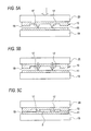
- FIGS. 5A to 5C are views illustrating a process of bonding two substrate members to each other by ultrasonic welding.
- FIG. 6 is a plan view of a substrate member 10 A which is a modified example of the substrate member 10 of the microchannel device 1 illustrated in FIG. 1 .
- FIG. 7 is a plan view of a substrate member 10 B which is a modified example of the substrate member 10 of the microchannel device 1 illustrated in FIG. 1 .
- FIG. 8 is a plan view of a microchannel device manufactured by Examples.
- FIG. 9 is a view illustrating a change of a channel height in the microchannel device manufactured in Comparative Example 1.
- FIG. 10 is a view illustrating a change of a channel height in the microchannel device manufactured in Example 1.
- FIG. 11 is a view illustrating a change of a channel height in the microchannel device manufactured in Comparative Example 2.
- FIG. 12 is a view illustrating a change of a channel height in the microchannel device manufactured in Example 2.
- a microchannel device to be described below passes a liquid sample containing an antigen such as allergen, as a detection target substance, through the microchannel device.
- an antigen such as allergen
- the antigen bound to a labeling substance which excites and emits light is captured within a channel, and light emission of the labeling substance bound to the captured antigen is observed, thereby detecting the antigen.
- the present invention is not limited thereto.
- FIG. 1 is a plan view of a microchannel device 1 according to an exemplary embodiment of the present invention.
- FIG. 2 is a cross-sectional view along line II-II of FIG. 1 .
- the microchannel device 1 includes a substrate 2 .
- the substrate 2 is configured by stacking and bonding two substantially rectangular substrate members 10 and 11 to each other.
- the microchannel device 1 as described above, is configured to detect an antigen by observing light emission of a labeling substance.
- at least one of the substrate members 10 and 11 is transparent.
- the substrate member 10 is a first substrate member
- the substrate member 11 is a second substrate member.
- a bonding surface of the substrate member 10 to be bonded to the substrate member 11 is formed with a fine recessed portion 12 in a predetermined pattern.
- Two holes 14 and 15 are formed to penetrate the substrate member 11 in a thickness direction.
- the substrate member 10 and the substrate member 11 are stacked with each other, and the substrate member 11 covers the recessed portion 12 of the substrate member 10 to form a channel 3 within the substrate 2 .
- the hole 14 becomes an introducing hole communicated with one end of the channel 3 and configured to introduce a liquid, such as a sample, into the channel 3 .
- the hole 15 becomes a discharge hole communicated with the other end of the channel 3 and configured to discharge the liquid which has flowed in the channel 3 .
- a detection portion 16 is provided in the substantially central section in the channel 3 .
- the detection portion 16 is provided with a detection unit configured to detect a detection target substance included in a sample.
- the microchannel device 1 is, as described above, configured to capture an antigen within a channel and detect the antigen. Thus, an antibody that specifically adsorbs and captures an antigen is fixed to the detection portion 16 .
- a liquid sample containing an antigen is subjected to pre-treatment in which a labeling substance which excites and emits light is bound to the antigen, and the sample which has been subjected to the pre-treatment is injected into the introducing hole 14 .
- a vacuum pump is connected to the discharge hole 15 , thereby making a pressure difference between the introducing hole 14 and the discharge bole 15 , so that the sample injected into the introducing hole 14 is drawn into the channel 3 .
- the antigen included in the sample is specifically adsorbed and captured by the antibody fixed to the surface of the detection portion 16 .
- Excitation light is irradiated to the detection portion 16 to observe light emission of the labeling substance bound to the antigen captured by the detection portion 16 .
- the antigen included in the sample is detected from the presence or absence of light emission, or the intensity of light emission.
- the labeling substance is bound to the antigen by the pre-treatment.
- a reaction portion may be provided at an upstream section of the detection portion 16 in the channel 3 , and then, a labeling substance may be attached to the surface of the reaction portion, or a carrier carrying the labeling substance may be disposed on the surface of the reaction portion. Accordingly, while a sample flows in the reaction portion, the labeling substance may be bound to the antigen included in the sample.
- the two substrate members 10 and 11 which form the channel 3 are bonded by ultrasonic welding.
- FIG. 3 is a plan view of the substrate member 10 provided with a protruding portion to be ultrasonically welded.
- FIG. 4 is a cross-sectional view along line IV-IV of FIG. 3 .
- a protruding portion 17 to be ultrasonically welded extends on the surface of the substrate member 10 .
- a protruding stopper portion 18 for stopping welding is provided on the surface of the substrate member 10 provided with the protruding portion 17 and is disposed around the protruding portion 17 .
- the protruding portion 17 protrudes from the surface of the substrate member 10 by a predetermined height H1 and extends to define the recessed portion 12 which becomes the channel 3 . That is, the recessed portion 12 is formed by the protruding portion 17 , and the protruding portion 17 surrounds the recessed portion 12 along the edge of the recessed portion 12 .
- the protruding portion 17 comes in contact with the substrate member 11 at the top of the protruding portion 17 .
- the top portion of the protruding portion 17 is melted and is adhered on the substrate member 11 as ultrasonic vibration is applied.
- the cross-section of the protruding portion 17 is preferably formed into a shape having a pointed top portion, and typically into a triangular shape so that ultrasonic vibration is concentrated on the top portion.
- the stopper portion 18 extends along the outer periphery of the surface of the substrate member 10 formed with the protruding portion 17 .
- the stopper portion 18 protrudes from the surface of the substrate member 10 by a predetermined height H2.
- the height H2 of the stopper portion 18 is smaller than the height H1 of the protruding portion 17 .
- the area of the top portion of the stopper portion 18 in plan view is sufficiently larger than the area of the protruding portion 17 of the microchannel device 1 in plan view.
- the top portion of the protruding portion 17 is welded and lowered, so that the stopper portion 18 comes in contact with the substrate member 11 . Accordingly, the ultrasonic vibration is dispersed, and the welding of the top portion of the protruding portion 17 is stopped. That is, the stopper portion 18 defines the height of the protruding portion 17 left after the ultrasonic welding. That is, the stopper portion 18 defines the depth of the recessed portion 12 defined by the protruding portion 17 , and finally defines the thickness of the channel 3 .
- the protruding portion 17 or the stopper portion 18 may be formed by injecting a resin into a form of the pattern of the protruding portion 17 or the stopper portion 18 , and solidifying the injected resin. Otherwise, the protruding portion 17 or the stopper portion 18 may be formed by performing a hot-emboss process in the pattern of the protruding portion 17 or the stopper portion 18 , on a flat resin plate.
- thermoplastic resin used for the material for the substrate members 10 and 11 may include a polyolefin-based resin such as a polyethylene resin or a polypropylene resin, a polystyrene-based resin, a polylactic acid-based resin, a polyacrylic resin such as polymethylmethacrylate, and a silicon-based resin such as polycarbonate.
- a polyolefin-based resin such as a polyethylene resin or a polypropylene resin
- polystyrene-based resin such as polylactic acid-based resin
- a polyacrylic resin such as polymethylmethacrylate
- silicon-based resin such as polycarbonate.
- a polyolefin-based resin excellent in, for example, acid resistance, alkali resistance, and chemical resistance is preferable.
- a polyolefin-based resin excellent in optical transparency is preferable.
- Antibodies are fixed at predetermined locations of the recessed portion 12 defined by the protruding portion 17 of the substrate member 10 .
- a gold thin film is deposited by sputtering, and a solution containing an antibody is quantitatively spotted on the gold thin film by a dispenser, so that the antibody is bound to the gold thin film.
- a blocking agent is additionally spotted thereto in order to suppress the labeling substance alone from being non-specifically adsorbed by the antibody.
- An immune stabilizer containing a protein as a main component is further spotted thereto so as to moisturize and stabilize the antibody.
- the substrate members 10 and 11 are bonded by ultrasonic welding to obtain the microchannel device 1 .
- FIGS. 5A to 5C are views illustrating a process of bonding two substrate members to each other by ultrasonic welding.
- the substrate member 11 is placed on a bearing block 19 , and the substrate member 10 formed with the protruding portion 17 is stacked on the substrate member 11 so that the top portion of the protruding portion 17 comes in contact with the surface of the substrate member 11 .
- An ultrasonic oscillation horn 20 which is a part of an ultrasonic oscillation device is stacked on the substrate member 10 to pressurize a stacked body of the substrate members 10 and 11 between the bearing block 19 and the horn 20 ( FIG. 5A ). Accordingly the top portion of the protruding portion 17 extending on the surface of the substrate member 10 is pressed against the surface of the substrate member 11 .
- a load applied to the stacked body of the substrate members 10 and 11 is generally gradually increased.
- the load applied to the stacked body is equal to or greater than a predetermined threshold, ultrasonic oscillation is initiated from the horn 20 , and ultrasonic vibration is applied to the substrate member 10 to initiate welding of the protruding portion 17 to the substrate member 11 ( FIG. 5B ).
- the above described threshold related to the load applied to the stacked body of the substrate members 10 and 11 may be set as a load which allows the protruding portion 17 to be in contact with a bonding surface of the substrate member 11 over the entire length of the protruding portion 17 .
- amplitude of ultrasonic vibration at the initiation time of the ultrasonic vibration (amplitude of vibration applied to the substrate member 10 from the ultrasonic oscillation horn 20 ) is set as a first value.
- An ultrasonic oscillation device includes a converter configured to generate vibration, a booster configured to amplify the vibration generated by the converter, and an ultrasonic oscillation horn configured to transfer the vibration amplified by the booster to a member.
- a voltage applied to the converter is adjusted to adjust the amplitude of vibration applied to the substrate member 10 from the ultrasonic oscillation horn 20 .
- the height of the protruding portion 17 is lowered as the protruding portion 17 is melted with the progress of ultrasonic welding. Then, when a predetermined time is elapsed from the initiation of the ultrasonic vibration, the amplitude is changed to a second value lower than the first value.
- a process of applying ultrasonic vibration to the substrate member 10 to weld the protruding portion 17 on the surface of the substrate member 11 includes a first ultrasonic welding process of applying the ultrasonic vibration at amplitude of the first value to the substrate member 10 , and a second ultrasonic welding process of applying the ultrasonic vibration at amplitude of the second value lower than the first value to the substrate member 10 after the first ultrasonic welding process is performed.
- the ultrasonic vibration is dispersed to stop the welding of the protruding portion 17 .
- the height of the protruding portion 17 becomes substantially the same as the height of the stopper portion 18 , which becomes the height of the channel 3 ( FIG. 5C ).
- the boundary between the two substrate members 10 and 11 , which is exposed in the channel 3 is closed over the entire length by ultrasonic welding of the protruding portion 17 .
- the ultrasonic welding of the protruding portion 17 is performed in a state where the protruding portion 17 is in contact with the bonding surface of the substrate member 11 over the entire length of the protruding portion 17 . Accordingly, the ultrasonic welding is uniformly performed over the entire length of the protruding portion 17 , the sealing property of the channel 3 is improved, and the bonding strength of the substrate members 10 and 11 is also improved.
- the length of the contact portion between the stopper portion 18 and the substrate member 11 in the cross-section passing through the stopper portion 18 and the protruding portion 17 becomes 3 times to 20 times the length of the protruding portion 17 welded on the substrate member 11 in the cross-section in a state where the welding of the protruding portion 17 is stopped.
- the shapes of the stopper portion 18 and the protruding portion 17 may be determined to obtain the relationship so that the shape control of the channel 3 may be performed with high precision.
- the amplitude of ultrasonic vibration is generally set as a large value to some extent so as to shorten a time required for bonding, or increase a bonding strength.
- the amplitude of the ultrasonic vibration may be set as a value as large as possible as long as the substrate member 10 and the substrate member 11 are not destroyed.
- a process of measuring a time required until a variation of height of the protruding portion 17 becomes a threshold or less is performed while gradually welding the protruding portion 17 on the surface of the substrate member 11 by applying ultrasonic vibration at amplitude of the first value to the substrate member 10 before the microchannel device 1 is manufactured.
- the time for performing the first ultrasonic welding process is set as a time longer than the time measured by the measuring process.
- a substrate member 10 and a substrate member 11 manufactured in the same designs as those used for manufacturing the microchannel device 1 are prepared.
- the substrate member 11 is placed on a bearing block 19 , and the substrate member 10 formed with a protruding portion 17 is stacked on the substrate member 11 so that the top portion of the protruding portion 17 comes in contact with the surface of the substrate member 11 .
- an ultrasonic oscillation horn 20 is stacked on the substrate member 10 to pressurize a stacked body of the substrate members 10 and 11 between the bearing block 19 and the horn 20 .
- ultrasonic oscillation is initiated from the horn 20 , and ultrasonic vibration at amplitude of a first value is applied to the substrate member 10 to initiate welding of the protruding portion 17 to the substrate member 11 .
- the height of a channel formed by the protruding portion 17 is measured at each of locations at a plurality of different distances from an end portion of the stacked body of the substrate member 10 and the substrate member 11 .
- the measurement of the height of the channel is performed by measuring an optical path difference between laser reflected lights from two surfaces, that is, a channel side surface of the substrate member 10 and a channel side surface of the substrate member 11 through, for example, a laser displacement gauge.
- a time from welding initiation until a variation of each of the protruding portion heights measured at all locations becomes a threshold or less is measured.
- the predetermined time as described above is set to be longer than the time measured in this manner. In this manner, a time required for bonding substrate members may be shortest, and the bonding strength of the substrate members may be increased while the height of the protruding portion 17 may become uniform.
- a second value set as amplitude of ultrasonic vibration may be properly set as a value at which welding is resumed.
- the second value is 0.5 times or less the first value so that once welding is stopped, the welding is smoothly and securely resumed.
- the stopper portion 18 provided in the substrate member 10 is provided along the outer periphery of the substrate member 10 .
- the configuration of the stopper portion 18 is not limited thereto.
- FIG. 6 is a plan view of a substrate member 10 A which is a modified example of the substrate member 10 of the microchannel device 1 illustrated in FIG. 1 .
- the substrate member 10 A is different from the substrate member 10 in that a stopper portion 18 A corresponding to the stopper portion 18 extends along the protruding portion 17 at the side of the protruding portion 17 .
- the stopper portion extends along the protruding portion such that the width of the stopper portion is constant within an error range of 50%, an interval separating the stopper portion and the protruding portion is equal to or less than the width of the stopper portion, and the width of the protruding portion is constant within an error range of 50%. Accordingly, when the microchannel device 1 is manufactured by using the substrate member 10 A, a distance between the protruding portion 17 and the stopper portion 18 A becomes shorter and constant, and thus the shape control of the channel 3 may be performed with higher precision.
- FIG. 7 is a plan view of a substrate member 10 B which is a modified example of the substrate member 10 of the microchannel device 1 illustrated in FIG. 1 .
- the substrate member 10 B is the same as the substrate member 10 A in that a stopper portion 18 B corresponding to the stopper portion 18 extends along the protruding portion 17 at the side of the protruding portion 17 , but is different from the substrate member 10 A in that the stopper portion 18 B is constituted by a plurality of sub-protruding portions 18 Ba arranged at intervals.
- a distance between the protruding portion 17 and the stopper portion 18 B becomes shorter and constant, and thus the shape control of the channel 3 may be performed with higher precision.
- H/K may be set as 0.5 or more so that the shape control of the channel 3 may be performed with higher precision.
- the stopper portion 18 , 18 A or 18 B is provided on the surface of the substrate member 10 provided with the protruding portion 17 , but the stopper portion 18 , 18 A or 18 B may be provided on the substrate member 11 . That is, the stopper portion 18 , 18 A or 18 B may be provided on the surface of the substrate member 11 to come in contact with the protruding portion 17 so that the stopper portion 18 , 18 A or 18 B is disposed around the protruding portion 17 in a state where the top portion of the protruding portion 17 is pressed against the surface of the substrate member 11 .
- a microchannel device configured as illustrated in FIG. 1 was manufactured by the method described in FIGS. 5A to 5C .
- the amplitude of the ultrasonic vibration applied to the substrate member 10 was constant without a change on the way.
- the amplitude of the ultrasonic vibration applied to the substrate member 10 was set as 40% of maximum amplitude of vibration which can be applied by an ultrasonic welding machine.
- the height of a channel was measured with respect to time elapsed from initiation of the ultrasonic vibration at each of locations at distances 11 mm, 17 mm, 23 nun and 29 mm from an end portion of a substrate 2 .
- FIG. 9 is a view illustrating a measurement result of the height of the channel in the manufacturing process of the microchannel device of Comparative Example 1. As illustrated in FIG. 9 , when the ultrasonic vibration at 40% of maximum amplitude was continuously applied, 0.15 sec later, a height variation of the channel at each location was reduced but the heights of the channel did not become uniform at all locations, thereby stopping welding.
- a microchannel device configured as illustrated in FIG. 1 was manufactured by the method described in FIGS. 5A to 5C .
- the amplitude of the ultrasonic vibration applied to the substrate member 10 was set as 40% of maximum amplitude (a first value), and 20% of maximum amplitude (a second value).
- the amplitude was set as the first value for about 0.17 sec which is much longer than 0.15 sec, that is, the time consumed until the welding was stopped in FIG. 9 .
- the height of a channel was measured with respect to time elapsed from initiation of the ultrasonic vibration.
- FIG. 10 is a view illustrating a measurement result of the height of the channel in the manufacturing process of the microchannel device of Example 1. As illustrated in FIG. 10 , when the amplitude was reduced from 40% of maximum amplitude to 20% in the middle of welding, the heights of the channel were gradually reduced at locations of 17 mm, 23 mm and. 29 mm, and then the heights of the channel became uniform at all locations at about 0.3 sec.
- the microchannel device was manufactured in the same mariner as in Comparative Example 1 except that the amplitude of the ultrasonic vibration applied to the substrate member 10 was set as 60% of maximum amplitude of vibration which can be applied by an ultrasonic welding machine, and the height of a channel was measured with respect to time elapsed from initiation of the ultrasonic vibration.
- FIG. 11 is a view illustrating a measurement result of the height of the channel in the manufacturing process of the microchannel device of Comparative Example 2. As illustrated in FIG. 11 , when the ultrasonic vibration at 60% of maximum amplitude was continuously applied, 0.07 sec later, a height variation of the channel at each location was reduced but the heights of the channel did not become uniform at all locations, thereby stopping welding.
- a microchannel device configured as illustrated in FIG. 1 was manufactured by the method described in FIGS. 5A to 5C .
- the amplitude of the ultrasonic vibration applied to the substrate member 10 was set as 60% of maximum amplitude (a first value), and 10% of maximum amplitude (a second value).
- the amplitude was set as the first value for 0.07 sec Which is the time consumed until the welding was stopped in FIG. 11 .
- the height of a channel was measured with respect to time elapsed from initiation of the ultrasonic vibration.
- FIG. 12 is a view illustrating a measurement result of the height of the channel in the manufacturing process of the microchannel device of Example 2. As illustrated in FIG. 12 , when the amplitude was reduced from 60% of maximum amplitude to 10% in the middle of welding, the heights of the channel were gradually reduced at locations of 17 mm, 23 mm and, 29 mm, and then the heights of the channel became uniform at all locations at about 0.13 sec.
- the second value is set to be 0.5 times or less the first value
- the resumption of welding may be smoothly and accurately performed even after the welding of the protruding portion 17 has stopped.
- a bonding method of bonding a first substrate member to a second substrate member including ultrasonically welding a protruding portion extending on a surface of the first substrate member to a surface of the second substrate member by applying ultrasonic vibration to the first substrate member in a state where a top portion of the protruding portion is pressed against the surface of the second substrate member, in which a protruding stopper portion for stopping welding is provided on the surface of the first substrate member formed with the protruding portion, or on the surface of the second substrate member to come in contact with the protruding portion in the pressed state, to be disposed around the protruding portion in the pressed state, and the ultrasonically welding includes a first process for applying ultrasonic vibration at amplitude as a first value to the first substrate member, and a second process for applying ultrasonic vibration to the first substrate member at amplitude as a second value lower than the first value after the first process.
- the stopper portion is constituted by a plurality of sub-protruding portions arranged at intervals, in which when a length of each of the plurality of the sub-protruding portions in an arrangement direction of the sub-protruding portions is set as H, and an interval between the sub-protruding portions in the arrangement direction is set as K, H/K is set as 0.5 or more.
- a length of a contact portion between the stopper portion and the first substrate member or the second substrate member in a cross-section passing through the stopper portion and the protruding portion in a state where the ultrasonically welding is stopped is 3 times to 20 times a length of the protruding portion welded on the second substrate member in the cross-section in a state where the ultrasonically welding is stopped.
- the bonding method further including, before the ultrasonically welding, previously measuring a time required until a variation of height of a protruding portion extending on a surface of a third substrate member having the same configuration as the first substrate member becomes a threshold or less while welding the protruding portion on a surface of a fourth substrate member having the same configuration as the second substrate member by applying ultrasonic vibration at amplitude as the first value to the third substrate member in a state where a top portion of the protruding portion is pressed against the surface of the fourth substrate member, in which in the ultrasonically welding, the first process is performed for a time longer than the time measured in the measuring of the time.
- a manufacturing method of manufacturing as microchannel device in which a channel is formed between a first substrate member and a second substrate member which are bonded to each other, the method including: ultrasonically welding a protruding portion extending on a surface of the first substrate member to a surface of the second substrate member by applying ultrasonic vibration to the first substrate member in a state where a top portion of the protruding portion is pressed against the surface of the second substrate member, the protruding portion corresponding to an edge of the channel, in which a protruding stopper portion for stopping welding is provided on the surface of the first substrate member formed with the protruding portion, or on the surface of the second substrate member to come in contact with the protruding portion in the pressed state to be disposed around the protruding portion in the pressed state, and the ultrasonically welding includes a first process for applying ultrasonic vibration at amplitude as a first value to the first substrate member, and a second process for applying ultrasonic vibration to the first substrate member at ampli
- the stopper portion is disposed along the protruding portion at a side portion of the protruding portion in the pressed state.
- the stopper portion is constituted by a plurality of sub-protruding portions arranged at intervals, in which when a length of each of the plurality of the sub-protruding portions in an arrangement direction of the sub-protruding portions is set as H, and an interval between the sub-protruding portions in the arrangement direction is set as K, is set as 0.5 or more.
- a length of a contact portion between the stopper portion and the first substrate member or the second substrate member in a cross-section passing through the stopper portion and the protruding portion in a state where the ultrasonically welding is stopped is 3 times to 20 times a length of the protruding portion welded on the second substrate member in the cross-section in a state where the ultrasonically welding is stopped.
- the manufacturing method in which the second value is 0.5 times or less the first value.
- the manufacturing method further including, before the ultrasonically welding, previously measuring a time required until a variation of height of a protruding portion extending on a surface of a third substrate member having the same configuration as the first substrate member becomes a threshold or less while welding the protruding portion on a surface of a fourth substrate member having the same configuration as the second substrate member by applying ultrasonic vibration at amplitude as the first value to the third substrate member in a state where a top portion of the protruding portion is pressed against the surface of the fourth substrate member, in which in the ultrasonically welding, the first process is performed for a time longer than the time measured in the measuring of the time.
Abstract
A bonding method includes ultrasonically welding a protruding portion extending on a surface of a first substrate member to a surface of a second substrate member by applying ultrasonic vibration to the first substrate member. A protruding stopper portion for stopping welding is provided on the surface of the first substrate member formed with the protruding portion, or on the surface of the second substrate member to come in contact with the protruding portion in a pressed state, to be disposed around the protruding portion in the pressed state. The ultrasonically welding includes a first process for applying ultrasonic vibration at amplitude as a first value to the first substrate member, and a second process for applying ultrasonic vibration to the first substrate member at amplitude as a second value lower than the first value after the first process.
Description
This application is based on and claims priority wider 35 USC 119 from Japanese Patent Application No. 2013-269638 filed on Dec. 26, 2013, the entire content of which is incorporated herein by reference.
1. Technical Field
The present invention relates to a bonding method and a method of manufacturing a microchannel device.
2. Related Art
A microchannel device has recently been used for analysis of a liquid sample. The microchannel device is configured to pass samples or other liquids through a microchannel to cause chemical or biochemical reactions in the microchannel so that a detection target substance included in a sample is detected.
A microchannel device is typically configured by stacking a plurality of substrate members so that a channel is formed between two adjacent substrate members. The two substrate members which form the channel are typically bonded by, for example, an adhesive tape. Also, there is known a channel in which two substrate members are bonded by ultrasonic welding in order to increase a sealing property of the channel (e.g., See, Patent Literature 1 (JP-A-2011-161578)).
In a method of manufacturing a microchannel device disclosed in Patent Literature 1, two substrate members (a substrate member formed with a protruding portion and a stopper and a flat substrate member) are stacked and applied with ultrasonic vibration under a predetermined pressurization condition so that the protruding portion is gradually welded on the surface of the flat substrate member. In this method, when the stopper and the flat substrate member come in contact with each other as the welding proceeds, the ultrasonic vibration is stopped, and a space sandwiched between the protruding portion and the substrate member is formed as a channel.
There are known various technologies for ultrasonic bonding. Patent Literature 2 (JP-A-3-183527) discloses a method of allowing bonding to be performed within a short time without reducing a bonding strength by gradually decreasing amplitude of ultrasonic waves from initiation of bonding when semiconductor chips are bonded by using an adhesive.
Patent Literature 3 (JP-A-2006-204983) discloses a method of easily and inexpensively manufacturing a microreactor in which a condition of a member pressing pressure with respect to oscillation energy and oscillation time is set to a desired value in ultrasonic oscillation.
As disclosed in Patent Literature 1, in a method of defining a height of a channel by using a stopper, when the stopper and a flat substrate member come in contact with each other in a larger area than a contact area between a protruding portion and the flat substrate member, a resistance between substrate members is increased. As a result, energy of ultrasonic oscillation is hardly transmitted to the protruding portion so that the welding of the protruding portion may be stopped.
Accordingly, in order to make the height of the microchannel uniform, it is required to bring substrate members in contact with each other at once over the all locations of a stopper. However, a microchannel device has one side length on the order of centimeters. Accordingly, the substrate members may not come in contact with each other at once over the all locations of the stopper due to, for example, warpage of the substrate members. In such a case, due to a resistance increase caused by contact between the stopper and the substrate member, welding of a protruding portion is stopped early. Accordingly, the height of the microchannel may not be uniform.
Patent Literatures 1 to 3 do not consider a problem in that welding of a protruding portion is early stopped by using a stopper, and the height of a channel becomes non-uniform, and thus do not disclose a means for solving the problem.
The present invention has been made in view of the above described circumstances, and an object thereof is to provide a bonding method in which a protruding portion for bonding two members to each other through ultrasonic welding may be welded without non-uniformity in height over the entire length of the protruding portion, and a method of manufacturing a microchannel device which may perform a control of a channel space with high precision.
An aspect of the present invention provides a bonding method of bonding a first substrate member to a second substrate member, the method comprising ultrasonically welding a protruding portion extending on a surface of the first substrate member to a surface of the second substrate member by applying ultrasonic vibration to the first substrate member in a state where a for portion of the protruding portion is pressed against the surface of the second substrate member, wherein a protruding stopper portion for stopping welding is provided on the surface of the first substrate member formed with the protruding portion, or on the surface of the second substrate member to come in contact with the protruding portion in the pressed state, to be disposed around the protruding portion in the pressed state, and the ultrasonically welding includes a first process for applying ultrasonic vibration at amplitude as a first value to the first substrate member, and a second process for applying ultrasonic vibration to the first substrate member at amplitude as a second value lower than the first value after the first process.
Another aspect of the present invention provides as manufacturing method of manufacturing a microchannel device in which a channel is formed between a first substrate member and a second substrate member which are bonded to each other, the method comprising: ultrasonically welding a protruding portion extending on a surface of the first substrate member to a surface of the second substrate member by applying ultrasonic vibration to the first substrate member in a state where a top portion of the protruding portion is pressed against the surface of the second substrate member, the protruding portion corresponding to an edge of the channel, wherein a protruding stopper portion for stopping welding is provided on the surface of the first substrate member formed with the protruding portion, or on the surface of the second substrate member to come in contact with the protruding portion in the pressed state to be disposed around the protruding portion in the pressed state, the ultrasonically welding includes a first process for applying ultrasonic vibration at amplitude as a first value to the first substrate member, and a second process for applying ultrasonic vibration to the first substrate member at amplitude as a second value lower than the first value after the first process.
According to the present invention, there is provided is bonding method in which a protruding portion for bonding two members to each other through ultrasonic welding may be welded without non-uniformity in height over the entire length of the protruding portion, and a method of manufacturing as microchannel device which may perform a control of as channel space with high precision.
Hereinafter, an exemplary embodiment of the present invention will be described with reference to drawings.
A microchannel device to be described below passes a liquid sample containing an antigen such as allergen, as a detection target substance, through the microchannel device. In the microchannel device, the antigen bound to a labeling substance which excites and emits light is captured within a channel, and light emission of the labeling substance bound to the captured antigen is observed, thereby detecting the antigen. However, the present invention is not limited thereto.
The microchannel device 1 includes a substrate 2. The substrate 2 is configured by stacking and bonding two substantially rectangular substrate members 10 and 11 to each other. The microchannel device 1, as described above, is configured to detect an antigen by observing light emission of a labeling substance. Thus, at least one of the substrate members 10 and 11 is transparent. The substrate member 10 is a first substrate member, and the substrate member 11 is a second substrate member.
A bonding surface of the substrate member 10 to be bonded to the substrate member 11 is formed with a fine recessed portion 12 in a predetermined pattern. Two holes 14 and 15 are formed to penetrate the substrate member 11 in a thickness direction.
The substrate member 10 and the substrate member 11 are stacked with each other, and the substrate member 11 covers the recessed portion 12 of the substrate member 10 to form a channel 3 within the substrate 2. The hole 14 becomes an introducing hole communicated with one end of the channel 3 and configured to introduce a liquid, such as a sample, into the channel 3. The hole 15 becomes a discharge hole communicated with the other end of the channel 3 and configured to discharge the liquid which has flowed in the channel 3.
A detection portion 16 is provided in the substantially central section in the channel 3. The detection portion 16 is provided with a detection unit configured to detect a detection target substance included in a sample. The microchannel device 1 is, as described above, configured to capture an antigen within a channel and detect the antigen. Thus, an antibody that specifically adsorbs and captures an antigen is fixed to the detection portion 16.
A method of detecting an antigen such as allergen by using the microchannel device 1 configured as described above will be briefly described.
A liquid sample containing an antigen is subjected to pre-treatment in which a labeling substance which excites and emits light is bound to the antigen, and the sample which has been subjected to the pre-treatment is injected into the introducing hole 14. A vacuum pump is connected to the discharge hole 15, thereby making a pressure difference between the introducing hole 14 and the discharge bole 15, so that the sample injected into the introducing hole 14 is drawn into the channel 3. While the sample is flowed in the detection portion 16, the antigen included in the sample is specifically adsorbed and captured by the antibody fixed to the surface of the detection portion 16. Excitation light is irradiated to the detection portion 16 to observe light emission of the labeling substance bound to the antigen captured by the detection portion 16. The antigen included in the sample is detected from the presence or absence of light emission, or the intensity of light emission.
In the above description, the labeling substance is bound to the antigen by the pre-treatment. However, a reaction portion may be provided at an upstream section of the detection portion 16 in the channel 3, and then, a labeling substance may be attached to the surface of the reaction portion, or a carrier carrying the labeling substance may be disposed on the surface of the reaction portion. Accordingly, while a sample flows in the reaction portion, the labeling substance may be bound to the antigen included in the sample.
As described above, feeding of the sample is made by pressure. A leakage of the sample has an effect on detection accuracy. Therefore, a high sealing property is required for the channel 3. Accordingly, the two substrate members 10 and 11 which form the channel 3 are bonded by ultrasonic welding.
In the microchannel device 1, a protruding portion 17 to be ultrasonically welded extends on the surface of the substrate member 10. A protruding stopper portion 18 for stopping welding is provided on the surface of the substrate member 10 provided with the protruding portion 17 and is disposed around the protruding portion 17.
The protruding portion 17 protrudes from the surface of the substrate member 10 by a predetermined height H1 and extends to define the recessed portion 12 which becomes the channel 3. That is, the recessed portion 12 is formed by the protruding portion 17, and the protruding portion 17 surrounds the recessed portion 12 along the edge of the recessed portion 12.
The protruding portion 17 comes in contact with the substrate member 11 at the top of the protruding portion 17. The top portion of the protruding portion 17 is melted and is adhered on the substrate member 11 as ultrasonic vibration is applied. The cross-section of the protruding portion 17 is preferably formed into a shape having a pointed top portion, and typically into a triangular shape so that ultrasonic vibration is concentrated on the top portion.
The stopper portion 18 extends along the outer periphery of the surface of the substrate member 10 formed with the protruding portion 17. The stopper portion 18 protrudes from the surface of the substrate member 10 by a predetermined height H2. The height H2 of the stopper portion 18 is smaller than the height H1 of the protruding portion 17. The area of the top portion of the stopper portion 18 in plan view is sufficiently larger than the area of the protruding portion 17 of the microchannel device 1 in plan view.
According to the progress of ultrasonic welding, the top portion of the protruding portion 17 is welded and lowered, so that the stopper portion 18 comes in contact with the substrate member 11. Accordingly, the ultrasonic vibration is dispersed, and the welding of the top portion of the protruding portion 17 is stopped. That is, the stopper portion 18 defines the height of the protruding portion 17 left after the ultrasonic welding. That is, the stopper portion 18 defines the depth of the recessed portion 12 defined by the protruding portion 17, and finally defines the thickness of the channel 3.
Hereinafter, an exemplary method of manufacturing the microchannel device 1 will be described.
As for a material for the substrate members 10 and 11, a thermoplastic resin is appropriately used. For example, the protruding portion 17 or the stopper portion 18 may be formed by injecting a resin into a form of the pattern of the protruding portion 17 or the stopper portion 18, and solidifying the injected resin. Otherwise, the protruding portion 17 or the stopper portion 18 may be formed by performing a hot-emboss process in the pattern of the protruding portion 17 or the stopper portion 18, on a flat resin plate.
Examples of the thermoplastic resin used for the material for the substrate members 10 and 11 may include a polyolefin-based resin such as a polyethylene resin or a polypropylene resin, a polystyrene-based resin, a polylactic acid-based resin, a polyacrylic resin such as polymethylmethacrylate, and a silicon-based resin such as polycarbonate. In order to circulate various liquids, as polyolefin-based resin excellent in, for example, acid resistance, alkali resistance, and chemical resistance is preferable. In order to observe light emission of the labeling substance, a polyolefin-based resin excellent in optical transparency is preferable.
Antibodies are fixed at predetermined locations of the recessed portion 12 defined by the protruding portion 17 of the substrate member 10. For example, a gold thin film is deposited by sputtering, and a solution containing an antibody is quantitatively spotted on the gold thin film by a dispenser, so that the antibody is bound to the gold thin film. Further, a blocking agent is additionally spotted thereto in order to suppress the labeling substance alone from being non-specifically adsorbed by the antibody. An immune stabilizer containing a protein as a main component is further spotted thereto so as to moisturize and stabilize the antibody. These are dried and the antibodies are fixed at predetermined locations of the recessed portion 12. The locations constitute the detection portion 16 in the channel 3.
Subsequently, the substrate members 10 and 11 are bonded by ultrasonic welding to obtain the microchannel device 1.
The substrate member 11 is placed on a bearing block 19, and the substrate member 10 formed with the protruding portion 17 is stacked on the substrate member 11 so that the top portion of the protruding portion 17 comes in contact with the surface of the substrate member 11. An ultrasonic oscillation horn 20 which is a part of an ultrasonic oscillation device is stacked on the substrate member 10 to pressurize a stacked body of the substrate members 10 and 11 between the bearing block 19 and the horn 20 (FIG. 5A ). Accordingly the top portion of the protruding portion 17 extending on the surface of the substrate member 10 is pressed against the surface of the substrate member 11.
A load applied to the stacked body of the substrate members 10 and 11 is generally gradually increased. When the load applied to the stacked body is equal to or greater than a predetermined threshold, ultrasonic oscillation is initiated from the horn 20, and ultrasonic vibration is applied to the substrate member 10 to initiate welding of the protruding portion 17 to the substrate member 11 (FIG. 5B ). The above described threshold related to the load applied to the stacked body of the substrate members 10 and 11 may be set as a load which allows the protruding portion 17 to be in contact with a bonding surface of the substrate member 11 over the entire length of the protruding portion 17.
Here, amplitude of ultrasonic vibration at the initiation time of the ultrasonic vibration (amplitude of vibration applied to the substrate member 10 from the ultrasonic oscillation horn 20) is set as a first value. An ultrasonic oscillation device includes a converter configured to generate vibration, a booster configured to amplify the vibration generated by the converter, and an ultrasonic oscillation horn configured to transfer the vibration amplified by the booster to a member. Here, a voltage applied to the converter is adjusted to adjust the amplitude of vibration applied to the substrate member 10 from the ultrasonic oscillation horn 20.
The height of the protruding portion 17 is lowered as the protruding portion 17 is melted with the progress of ultrasonic welding. Then, when a predetermined time is elapsed from the initiation of the ultrasonic vibration, the amplitude is changed to a second value lower than the first value.
In this manner, a process of applying ultrasonic vibration to the substrate member 10 to weld the protruding portion 17 on the surface of the substrate member 11 includes a first ultrasonic welding process of applying the ultrasonic vibration at amplitude of the first value to the substrate member 10, and a second ultrasonic welding process of applying the ultrasonic vibration at amplitude of the second value lower than the first value to the substrate member 10 after the first ultrasonic welding process is performed.
After the amplitude is changed to the second value, when the stopper portion 18 comes in contact with the substrate member 11 at all locations, the ultrasonic vibration is dispersed to stop the welding of the protruding portion 17. The height of the protruding portion 17 becomes substantially the same as the height of the stopper portion 18, which becomes the height of the channel 3 (FIG. 5C ).
In the obtained microchannel device 1, the boundary between the two substrate members 10 and 11, which is exposed in the channel 3, is closed over the entire length by ultrasonic welding of the protruding portion 17. The ultrasonic welding of the protruding portion 17 is performed in a state where the protruding portion 17 is in contact with the bonding surface of the substrate member 11 over the entire length of the protruding portion 17. Accordingly, the ultrasonic welding is uniformly performed over the entire length of the protruding portion 17, the sealing property of the channel 3 is improved, and the bonding strength of the substrate members 10 and 11 is also improved.
The length of the contact portion between the stopper portion 18 and the substrate member 11 in the cross-section passing through the stopper portion 18 and the protruding portion 17 becomes 3 times to 20 times the length of the protruding portion 17 welded on the substrate member 11 in the cross-section in a state where the welding of the protruding portion 17 is stopped. The shapes of the stopper portion 18 and the protruding portion 17 may be determined to obtain the relationship so that the shape control of the channel 3 may be performed with high precision.
Here, a time for performing the first ultrasonic welding process (the predetermined time) will be described.
When the substrate member 10 is bonded to the substrate member 11, the amplitude of ultrasonic vibration is generally set as a large value to some extent so as to shorten a time required for bonding, or increase a bonding strength. Specifically, the amplitude of the ultrasonic vibration may be set as a value as large as possible as long as the substrate member 10 and the substrate member 11 are not destroyed.
However, the inventor found that when the substrate member 10 and the substrate member 11 are welded to each other at fixed large amplitude of ultrasonic vibration, the welding may be stopped in a state where the height of the protruding portion 17 is larger than a desired value at some locations of the substrate member. This may be because according to the high amplitude of the ultrasonic vibration, energy of ultrasonic vibration is easily dispersed into the stopper portion 18 due to a resistance increase caused by contact between the stopper portion 18 and the substrate member 11.
Accordingly, in the present exemplary embodiment, a process of measuring a time required until a variation of height of the protruding portion 17 becomes a threshold or less is performed while gradually welding the protruding portion 17 on the surface of the substrate member 11 by applying ultrasonic vibration at amplitude of the first value to the substrate member 10 before the microchannel device 1 is manufactured. The time for performing the first ultrasonic welding process is set as a time longer than the time measured by the measuring process.
Specifically, before the microchannel device 1 is manufactured, a substrate member 10 and a substrate member 11 manufactured in the same designs as those used for manufacturing the microchannel device 1 are prepared. The substrate member 11 is placed on a bearing block 19, and the substrate member 10 formed with a protruding portion 17 is stacked on the substrate member 11 so that the top portion of the protruding portion 17 comes in contact with the surface of the substrate member 11. Subsequently, an ultrasonic oscillation horn 20 is stacked on the substrate member 10 to pressurize a stacked body of the substrate members 10 and 11 between the bearing block 19 and the horn 20. When the load applied to the stacked body is equal to or greater than a predetermined threshold, ultrasonic oscillation is initiated from the horn 20, and ultrasonic vibration at amplitude of a first value is applied to the substrate member 10 to initiate welding of the protruding portion 17 to the substrate member 11.
During the welding, the height of a channel formed by the protruding portion 17 is measured at each of locations at a plurality of different distances from an end portion of the stacked body of the substrate member 10 and the substrate member 11. The measurement of the height of the channel is performed by measuring an optical path difference between laser reflected lights from two surfaces, that is, a channel side surface of the substrate member 10 and a channel side surface of the substrate member 11 through, for example, a laser displacement gauge.
Then, a time from welding initiation until a variation of each of the protruding portion heights measured at all locations becomes a threshold or less is measured. The predetermined time as described above is set to be longer than the time measured in this manner. In this manner, a time required for bonding substrate members may be shortest, and the bonding strength of the substrate members may be increased while the height of the protruding portion 17 may become uniform.
A second value set as amplitude of ultrasonic vibration may be properly set as a value at which welding is resumed. However, it is preferable that the second value is 0.5 times or less the first value so that once welding is stopped, the welding is smoothly and securely resumed.
So far, the stopper portion 18 provided in the substrate member 10 is provided along the outer periphery of the substrate member 10. However, the configuration of the stopper portion 18 is not limited thereto.
The substrate member 10A is different from the substrate member 10 in that a stopper portion 18A corresponding to the stopper portion 18 extends along the protruding portion 17 at the side of the protruding portion 17. Here, in a preferred aspect, the stopper portion extends along the protruding portion such that the width of the stopper portion is constant within an error range of 50%, an interval separating the stopper portion and the protruding portion is equal to or less than the width of the stopper portion, and the width of the protruding portion is constant within an error range of 50%. Accordingly, when the microchannel device 1 is manufactured by using the substrate member 10A, a distance between the protruding portion 17 and the stopper portion 18A becomes shorter and constant, and thus the shape control of the channel 3 may be performed with higher precision.
The substrate member 10B is the same as the substrate member 10A in that a stopper portion 18B corresponding to the stopper portion 18 extends along the protruding portion 17 at the side of the protruding portion 17, but is different from the substrate member 10A in that the stopper portion 18B is constituted by a plurality of sub-protruding portions 18Ba arranged at intervals.
According to the substrate member 10B, a distance between the protruding portion 17 and the stopper portion 18B becomes shorter and constant, and thus the shape control of the channel 3 may be performed with higher precision. When the length of each of the sub-protruding portions 18Ba in the arrangement direction of the plurality of sub-protruding portions 18Ba is set as H, and the interval between the sub-protruding portions 18Ba in the arrangement direction is set as K, H/K may be set as 0.5 or more so that the shape control of the channel 3 may be performed with higher precision.
In the above description, the stopper portion 18, 18A or 18B is provided on the surface of the substrate member 10 provided with the protruding portion 17, but the stopper portion 18, 18A or 18B may be provided on the substrate member 11. That is, the stopper portion 18, 18A or 18B may be provided on the surface of the substrate member 11 to come in contact with the protruding portion 17 so that the stopper portion 18, 18A or 18B is disposed around the protruding portion 17 in a state where the top portion of the protruding portion 17 is pressed against the surface of the substrate member 11.
Hereinafter, Examples of the present invention will be described. In the following Examples, as for an ultrasonic welding machine used for bonding two substrate members, a machine manufactured by Japan Emerson Co., Ltd. was used. An oscillator model 2000 Xdt (20:1.25) was used, an actuator model aed2.5 was used, and a converter CJ-20 was used.
A microchannel device configured as illustrated in FIG. 1 was manufactured by the method described in FIGS. 5A to 5C . However, the amplitude of the ultrasonic vibration applied to the substrate member 10 was constant without a change on the way. The amplitude of the ultrasonic vibration applied to the substrate member 10 was set as 40% of maximum amplitude of vibration which can be applied by an ultrasonic welding machine. In the microchannel device during the manufacturing, as illustrated in FIG. 8 , the height of a channel was measured with respect to time elapsed from initiation of the ultrasonic vibration at each of locations at distances 11 mm, 17 mm, 23 nun and 29 mm from an end portion of a substrate 2.
A microchannel device configured as illustrated in FIG. 1 was manufactured by the method described in FIGS. 5A to 5C . The amplitude of the ultrasonic vibration applied to the substrate member 10 was set as 40% of maximum amplitude (a first value), and 20% of maximum amplitude (a second value). The amplitude was set as the first value for about 0.17 sec which is much longer than 0.15 sec, that is, the time consumed until the welding was stopped in FIG. 9 . In the same manner as in Comparative Example 1, in the microchannel device during the manufacturing, the height of a channel was measured with respect to time elapsed from initiation of the ultrasonic vibration.
The microchannel device was manufactured in the same mariner as in Comparative Example 1 except that the amplitude of the ultrasonic vibration applied to the substrate member 10 was set as 60% of maximum amplitude of vibration which can be applied by an ultrasonic welding machine, and the height of a channel was measured with respect to time elapsed from initiation of the ultrasonic vibration.
A microchannel device configured as illustrated in FIG. 1 was manufactured by the method described in FIGS. 5A to 5C . The amplitude of the ultrasonic vibration applied to the substrate member 10 was set as 60% of maximum amplitude (a first value), and 10% of maximum amplitude (a second value). The amplitude was set as the first value for 0.07 sec Which is the time consumed until the welding was stopped in FIG. 11 . In the same manner as in Comparative Example 2, in the microchannel device during the manufacturing, the height of a channel was measured with respect to time elapsed from initiation of the ultrasonic vibration.
As described above, when the second value is set to be 0.5 times or less the first value, the resumption of welding may be smoothly and accurately performed even after the welding of the protruding portion 17 has stopped.
As described above, in the present specification, the following items are disclosed.
It is disclosed a bonding method of bonding a first substrate member to a second substrate member, the method including ultrasonically welding a protruding portion extending on a surface of the first substrate member to a surface of the second substrate member by applying ultrasonic vibration to the first substrate member in a state where a top portion of the protruding portion is pressed against the surface of the second substrate member, in which a protruding stopper portion for stopping welding is provided on the surface of the first substrate member formed with the protruding portion, or on the surface of the second substrate member to come in contact with the protruding portion in the pressed state, to be disposed around the protruding portion in the pressed state, and the ultrasonically welding includes a first process for applying ultrasonic vibration at amplitude as a first value to the first substrate member, and a second process for applying ultrasonic vibration to the first substrate member at amplitude as a second value lower than the first value after the first process.
It is disclosed the bonding method, in which the stopper portion is disposed along the protruding portion at a side portion of the protruding portion in the pressed state.
It is disclosed the bonding method, in which the stopper portion is constituted by a plurality of sub-protruding portions arranged at intervals, in which when a length of each of the plurality of the sub-protruding portions in an arrangement direction of the sub-protruding portions is set as H, and an interval between the sub-protruding portions in the arrangement direction is set as K, H/K is set as 0.5 or more.
It is disclosed the bonding method, in which a length of a contact portion between the stopper portion and the first substrate member or the second substrate member in a cross-section passing through the stopper portion and the protruding portion in a state where the ultrasonically welding is stopped is 3 times to 20 times a length of the protruding portion welded on the second substrate member in the cross-section in a state where the ultrasonically welding is stopped.
It is disclosed the bonding method, in which the second value is 0.5 times or less the first value.
It is disclosed the bonding method, further including, before the ultrasonically welding, previously measuring a time required until a variation of height of a protruding portion extending on a surface of a third substrate member having the same configuration as the first substrate member becomes a threshold or less while welding the protruding portion on a surface of a fourth substrate member having the same configuration as the second substrate member by applying ultrasonic vibration at amplitude as the first value to the third substrate member in a state where a top portion of the protruding portion is pressed against the surface of the fourth substrate member, in which in the ultrasonically welding, the first process is performed for a time longer than the time measured in the measuring of the time.
It is disclosed a manufacturing method of manufacturing as microchannel device in which a channel is formed between a first substrate member and a second substrate member which are bonded to each other, the method including: ultrasonically welding a protruding portion extending on a surface of the first substrate member to a surface of the second substrate member by applying ultrasonic vibration to the first substrate member in a state where a top portion of the protruding portion is pressed against the surface of the second substrate member, the protruding portion corresponding to an edge of the channel, in which a protruding stopper portion for stopping welding is provided on the surface of the first substrate member formed with the protruding portion, or on the surface of the second substrate member to come in contact with the protruding portion in the pressed state to be disposed around the protruding portion in the pressed state, and the ultrasonically welding includes a first process for applying ultrasonic vibration at amplitude as a first value to the first substrate member, and a second process for applying ultrasonic vibration to the first substrate member at amplitude as a second value lower than the first value after the first process.
It is disclosed the manufacturing method, in which the stopper portion is disposed along the protruding portion at a side portion of the protruding portion in the pressed state.
It is disclosed the manufacturing method, in which the stopper portion is constituted by a plurality of sub-protruding portions arranged at intervals, in which when a length of each of the plurality of the sub-protruding portions in an arrangement direction of the sub-protruding portions is set as H, and an interval between the sub-protruding portions in the arrangement direction is set as K, is set as 0.5 or more.
It is disclosed the manufacturing method, in which a length of a contact portion between the stopper portion and the first substrate member or the second substrate member in a cross-section passing through the stopper portion and the protruding portion in a state where the ultrasonically welding is stopped is 3 times to 20 times a length of the protruding portion welded on the second substrate member in the cross-section in a state where the ultrasonically welding is stopped.
It is disclosed the manufacturing method, in which the second value is 0.5 times or less the first value.
It is disclosed the manufacturing method, further including, before the ultrasonically welding, previously measuring a time required until a variation of height of a protruding portion extending on a surface of a third substrate member having the same configuration as the first substrate member becomes a threshold or less while welding the protruding portion on a surface of a fourth substrate member having the same configuration as the second substrate member by applying ultrasonic vibration at amplitude as the first value to the third substrate member in a state where a top portion of the protruding portion is pressed against the surface of the fourth substrate member, in which in the ultrasonically welding, the first process is performed for a time longer than the time measured in the measuring of the time.
Claims (12)
1. A bonding method of bonding a first substrate member to a second substrate member, the method comprising ultrasonically welding a protruding portion extending on a surface of the first substrate member to a surface of the second substrate member by applying ultrasonic vibration to the first substrate member in a state where a top portion of the protruding portion is pressed against the surface of the second substrate member,
wherein a protruding stopper portion for stopping welding is provided on the surface of the first substrate member formed with the protruding portion, or on the surface of the second substrate member to come in contact with the protruding portion in the pressed state, to be disposed around the protruding portion in the pressed state, and
the ultrasonically welding includes a first process for applying ultrasonic vibration at amplitude as a first value to the first substrate member, and a second process for applying ultrasonic vibration to the first substrate member at amplitude as a second value lower than the first value after the first process.
2. The bonding method of claim 1 , wherein the stopper portion is disposed along the protruding portion at a side portion of the protruding portion in the pressed state.
3. The bonding method of claim 2 , wherein the stopper portion is constituted by a plurality of sub-protruding portions arranged at intervals,
wherein when a length of each of the plurality of the sub-protruding portions in an arrangement direction of the sub-protruding portions is set as H, and an interval between the sub-protruding portions in the arrangement direction is set as K, H/K is set as 0.5 or more.
4. The bonding method of claim 1 , wherein a length of a contact portion between the stopper portion and the first substrate member or the second substrate member in a cross-section passing through the stopper portion and the protruding portion in a state where the ultrasonically welding is stopped is 3 times to 20 times a length of the protruding portion welded on the second substrate member in the cross-section in a state where the ultrasonically welding is stopped.
5. The bonding method of claim 1 , wherein the second value is 0.5 times or less the first value.
6. The bonding method of claim 1 , further comprising, before the ultrasonically welding, previously measuring a time required until a variation of height of a protruding portion extending on a surface of a third substrate member having the same configuration as the first substrate member becomes a threshold or less while welding the protruding portion on a surface of a fourth substrate member having the same configuration as the second substrate member by applying ultrasonic vibration at amplitude as the first value to the third substrate member in a state where a top portion of the protruding portion is pressed against the surface of the fourth substrate member,
wherein in the ultrasonically welding, the first process is performed for a time longer than the time measured in the measuring of the time.
7. A manufacturing method of manufacturing a microchannel device in which a channel is formed between a first substrate member and a second substrate member which are bonded to each other, the method comprising:
ultrasonically welding a protruding portion extending on a surface of the first substrate member to a surface of the second substrate member by applying ultrasonic vibration to the first substrate member in a state where a top portion of the protruding portion is pressed against the surface of the second substrate member, the protruding portion corresponding to an edge of the channel,
wherein a protruding stopper portion for stopping welding is provided on the surface of the first substrate member formed with the protruding portion, or on the surface of the second substrate member to come in contact with the protruding portion in the pressed state to be disposed around the protruding portion in the pressed state, and
the ultrasonically welding includes a first process for applying ultrasonic vibration at amplitude as a first value to the first substrate member, and a second process for applying ultrasonic vibration to the first substrate member at amplitude as a second value lower than the first value after the first process.
8. The manufacturing method of claim 7 , wherein the stopper portion is disposed along the protruding portion at a side portion of the protruding portion in the pressed state.
9. The manufacturing method of claim 8 , wherein the stopper portion is constituted by a plurality of sub-protruding portions arranged at intervals,
wherein when a length of each of the plurality of the sub-protruding portions in an arrangement direction of the sub-protruding portions is set as H, and an interval between the sub-protruding portions in the arrangement direction is set as K, H/K is set as 0.5 or more.
10. The manufacturing method of claim 7 , wherein a length of a contact portion between the stopper portion and the first substrate member or the second substrate member in a cross-section passing through the stopper portion and the protruding portion in a state where the ultrasonically welding is stopped is 3 times to 20 times a length of the protruding portion welded on the second substrate member in the cross-section in a state where the ultrasonically welding is stopped.
11. The manufacturing method of claim 7 , wherein the second value is 0.5 times or less the first value.
12. The manufacturing method of claim 7 , further comprising, before the ultrasonically welding, previously measuring a time required until a variation of height of a protruding portion extending on a surface of a third substrate member having the same configuration as the first substrate member becomes a threshold or less while welding the protruding portion on a surface of a fourth substrate member having the same configuration as the second substrate member by applying ultrasonic vibration at amplitude as the first value to the third substrate member in a state where a top portion of the protruding portion is pressed against the surface of the fourth substrate member,
wherein in the ultrasonically welding, the first process is performed for a time longer than the time measured in the measuring of the time.
Applications Claiming Priority (2)
| Application Number | Priority Date | Filing Date | Title |
|---|---|---|---|
| JP2013-269638 | 2013-12-26 | ||
| JP2013269638A JP5933518B2 (en) | 2013-12-26 | 2013-12-26 | Bonding method and manufacturing method of microchannel device |
Publications (2)
| Publication Number | Publication Date |
|---|---|
| US20150183154A1 US20150183154A1 (en) | 2015-07-02 |
| US9694537B2 true US9694537B2 (en) | 2017-07-04 |
Family
ID=52282480
Family Applications (1)
| Application Number | Title | Priority Date | Filing Date |
|---|---|---|---|
| US14/581,814 Active 2035-08-17 US9694537B2 (en) | 2013-12-26 | 2014-12-23 | Bonding method and method of manufacturing microchannel device |
Country Status (3)
| Country | Link |
|---|---|
| US (1) | US9694537B2 (en) |
| EP (1) | EP2889121B1 (en) |
| JP (1) | JP5933518B2 (en) |
Cited By (1)
| Publication number | Priority date | Publication date | Assignee | Title |
|---|---|---|---|---|
| US20210346977A1 (en) * | 2017-09-15 | 2021-11-11 | Tech-Sonic, Inc. | Dual Cam Servo Weld Splicer |
Families Citing this family (5)
| Publication number | Priority date | Publication date | Assignee | Title |
|---|---|---|---|---|
| JP6010641B2 (en) * | 2015-01-28 | 2016-10-19 | 富士重工業株式会社 | Resin member and joining method of resin member |
| EP3544790B1 (en) * | 2016-11-23 | 2023-12-27 | Siemens Healthineers Nederland B.V. | Ultrasonic welding of a microfluidic device |
| JP7220441B2 (en) * | 2017-10-16 | 2023-02-10 | ヤマトエスロン株式会社 | MICROCHIP MANUFACTURING METHOD AND CHIP MEMBER |
| CN109895404B (en) * | 2017-12-11 | 2022-05-06 | 合肥海尔滚筒洗衣机有限公司 | Welding method of electric appliance display device |
| US20210055206A1 (en) * | 2018-02-16 | 2021-02-25 | Kyocera Corporation | Flow path device and measurement apparatus |
Citations (8)
| Publication number | Priority date | Publication date | Assignee | Title |
|---|---|---|---|---|
| JPH03183527A (en) | 1989-12-13 | 1991-08-09 | Hitachi Constr Mach Co Ltd | Ultrasonic joining equipment |
| US5658408A (en) | 1992-04-21 | 1997-08-19 | Branson Ultrasonics Corporation | Method for processing workpieces by ultrasonic energy |
| JPH1110738A (en) | 1997-06-19 | 1999-01-19 | Fuji Photo Film Co Ltd | Method for controlling welding in ultrasonic welding process |
| JPH1120024A (en) | 1997-07-02 | 1999-01-26 | Fuji Photo Film Co Ltd | Ultrasonic welding machine |
| US6066216A (en) | 1999-02-05 | 2000-05-23 | Biometric Imaging, Inc. | Mesa forming weld depth limitation feature for use with energy director in ultrasonic welding |
| US6152350A (en) | 1997-06-19 | 2000-11-28 | Fuji Photo Film Co., Ltd. | Ultrasonic welding device and method, and a magnetic tape cartridge reel welding device and method |
| JP2006204983A (en) | 2005-01-25 | 2006-08-10 | Sekisui Chem Co Ltd | Method of manufacturing micro-reactor |
| JP2011161578A (en) | 2010-02-10 | 2011-08-25 | Fujifilm Corp | Joining method, and method for manufacturing microchannel device |
Family Cites Families (4)
| Publication number | Priority date | Publication date | Assignee | Title |
|---|---|---|---|---|
| US6156270A (en) * | 1992-05-21 | 2000-12-05 | Biosite Diagnostics, Inc. | Diagnostic devices and apparatus for the controlled movement of reagents without membranes |
| GB9800263D0 (en) * | 1998-01-08 | 1998-03-04 | Bio Diagnostics Ltd | A device for testing liquids |
| KR100572207B1 (en) * | 2003-12-18 | 2006-04-19 | 주식회사 디지탈바이오테크놀러지 | Bonding method of plastic microchip |
| KR100948598B1 (en) * | 2007-12-17 | 2010-03-24 | 한국전자통신연구원 | Microfluidic device and Method for microfluidic device based on ultrasonic welding |
-
2013
- 2013-12-26 JP JP2013269638A patent/JP5933518B2/en active Active
-
2014
- 2014-12-22 EP EP14199585.2A patent/EP2889121B1/en active Active
- 2014-12-23 US US14/581,814 patent/US9694537B2/en active Active
Patent Citations (9)
| Publication number | Priority date | Publication date | Assignee | Title |
|---|---|---|---|---|
| JPH03183527A (en) | 1989-12-13 | 1991-08-09 | Hitachi Constr Mach Co Ltd | Ultrasonic joining equipment |
| US5658408A (en) | 1992-04-21 | 1997-08-19 | Branson Ultrasonics Corporation | Method for processing workpieces by ultrasonic energy |
| JPH1110738A (en) | 1997-06-19 | 1999-01-19 | Fuji Photo Film Co Ltd | Method for controlling welding in ultrasonic welding process |
| US6152350A (en) | 1997-06-19 | 2000-11-28 | Fuji Photo Film Co., Ltd. | Ultrasonic welding device and method, and a magnetic tape cartridge reel welding device and method |
| JPH1120024A (en) | 1997-07-02 | 1999-01-26 | Fuji Photo Film Co Ltd | Ultrasonic welding machine |
| US6066216A (en) | 1999-02-05 | 2000-05-23 | Biometric Imaging, Inc. | Mesa forming weld depth limitation feature for use with energy director in ultrasonic welding |
| JP2002536210A (en) | 1999-02-05 | 2002-10-29 | バイオメトリック イメージング インコーポレイテッド | Welding depth limiting feature to form terraces for use with energy directors in ultrasonic welding |
| JP2006204983A (en) | 2005-01-25 | 2006-08-10 | Sekisui Chem Co Ltd | Method of manufacturing micro-reactor |
| JP2011161578A (en) | 2010-02-10 | 2011-08-25 | Fujifilm Corp | Joining method, and method for manufacturing microchannel device |
Non-Patent Citations (2)
| Title |
|---|
| Extended European Search Report dated May 11, 2015, issued in corresponding European Patent Application No. 14199585.2. |
| Japanese Office Action and English translation dated Jan. 5, 2016 for corresponding Application No. 2013-269638. |
Cited By (2)
| Publication number | Priority date | Publication date | Assignee | Title |
|---|---|---|---|---|
| US20210346977A1 (en) * | 2017-09-15 | 2021-11-11 | Tech-Sonic, Inc. | Dual Cam Servo Weld Splicer |
| US11517977B2 (en) * | 2017-09-15 | 2022-12-06 | Tech-Sonic, Inc. | Dual cam servo weld splicer |
Also Published As
| Publication number | Publication date |
|---|---|
| JP2015125058A (en) | 2015-07-06 |
| EP2889121A1 (en) | 2015-07-01 |
| EP2889121B1 (en) | 2020-09-30 |
| JP5933518B2 (en) | 2016-06-08 |
| US20150183154A1 (en) | 2015-07-02 |
Similar Documents
| Publication | Publication Date | Title |
|---|---|---|
| US9694537B2 (en) | Bonding method and method of manufacturing microchannel device | |
| KR102070469B1 (en) | Microfluidic assay assemblies and methods of manufacture | |
| CN101048338B (en) | Fluid container composed of two plates | |
| JP5889639B2 (en) | Disc type analysis chip | |
| JP2017508956A (en) | Microfluidic chip and real-time analyzer using the same | |
| WO2006106848A1 (en) | Method for bonding substrates, method for forming chip, and chip | |
| US20120275972A1 (en) | Joining method and joint for microfluidic components | |
| JP5410419B2 (en) | Pressure-sensitive adhesive sheet for micro-analysis chip, micro-analysis chip, and manufacturing method thereof | |
| JP2007240461A (en) | Plastic microchip, joining method therefor, and biochip or micro analytical chip using the same | |
| JP2011161578A (en) | Joining method, and method for manufacturing microchannel device | |
| EP2353721A2 (en) | Microfluidic device | |
| US9079359B2 (en) | Microchip and method of manufacturing the same | |
| JP2008157644A (en) | Plastic microchip, and biochip or micro analysis chip using the same | |
| JP4752364B2 (en) | Plastic bonding method, and biochip or microanalysis chip manufactured using the method | |
| JP2008203186A (en) | Substrate laminating method, manufacturing method of microchip, and the microchip | |
| JP2004106508A (en) | Bonded part structure of plate | |
| JP2014109564A (en) | Target substance detection microchip | |
| JP2008076208A (en) | Plastic microchip, biochip using it or microanalyzing chip | |
| JP5196132B2 (en) | Microchip | |
| JP4072175B2 (en) | Substrate bonding method, chip forming method, and chip | |
| US9138745B2 (en) | Microchip | |
| JP2006346626A (en) | Reaction chip | |
| JP2005031064A (en) | Liquid inspection chip, and its manufacturing method | |
| JP5042147B2 (en) | Fluid handling equipment | |
| JP2006076246A (en) | Substrate lamination method, chip forming method using the lamination method and chip |
Legal Events
| Date | Code | Title | Description |
|---|---|---|---|
| AS | Assignment |
Owner name: FUJIFILM CORPORATION, JAPAN Free format text: ASSIGNMENT OF ASSIGNORS INTEREST;ASSIGNOR:KATO, KOTA;REEL/FRAME:034585/0021 Effective date: 20141222 |
|
| STCF | Information on status: patent grant |
Free format text: PATENTED CASE |
|
| MAFP | Maintenance fee payment |
Free format text: PAYMENT OF MAINTENANCE FEE, 4TH YEAR, LARGE ENTITY (ORIGINAL EVENT CODE: M1551); ENTITY STATUS OF PATENT OWNER: LARGE ENTITY Year of fee payment: 4 |