US9692532B2 - Method and wireless communication device for antenna deployment determination - Google Patents
Method and wireless communication device for antenna deployment determination Download PDFInfo
- Publication number
- US9692532B2 US9692532B2 US13/666,991 US201213666991A US9692532B2 US 9692532 B2 US9692532 B2 US 9692532B2 US 201213666991 A US201213666991 A US 201213666991A US 9692532 B2 US9692532 B2 US 9692532B2
- Authority
- US
- United States
- Prior art keywords
- antenna port
- antenna
- wireless communication
- communication device
- radio signal
- Prior art date
- Legal status (The legal status is an assumption and is not a legal conclusion. Google has not performed a legal analysis and makes no representation as to the accuracy of the status listed.)
- Active, expires
Links
Images


Classifications
-
- H—ELECTRICITY
- H04—ELECTRIC COMMUNICATION TECHNIQUE
- H04B—TRANSMISSION
- H04B17/00—Monitoring; Testing
- H04B17/30—Monitoring; Testing of propagation channels
- H04B17/309—Measuring or estimating channel quality parameters
- H04B17/318—Received signal strength
-
- H—ELECTRICITY
- H04—ELECTRIC COMMUNICATION TECHNIQUE
- H04B—TRANSMISSION
- H04B17/00—Monitoring; Testing
- H04B17/10—Monitoring; Testing of transmitters
- H04B17/101—Monitoring; Testing of transmitters for measurement of specific parameters of the transmitter or components thereof
- H04B17/102—Power radiated at antenna
Definitions
- a wireless communication system supporting a multiple-input multiple-output (MIMO) technology may use multiple antennas for wireless signal transmission and reception. Therefore, vendors of wireless communication devices usually manufacture products, such as smart phones or laptops, with several antenna ports for various applications, e.g., radio signals transceiving in Universal Mobile Communication System (UMTS)/Long Term Evolution (LTE) system or radio signals reception in global navigation satellite systems (GNSS).
- UMTS Universal Mobile Communication System
- LTE Long Term Evolution
- GNSS global navigation satellite systems
- a wireless communication device supporting 8 ⁇ 8 MIMO may have 8 antenna ports, such that up to 8 antennas can be attached to the wireless communication device. If the wireless communication device is to be operated in a 4 ⁇ 4 MIMO environment, only 4 antennas are needed. Therefore, 4 antenna ports have antennas attached, while the other 4 antenna ports do not.
- Such design provides flexibility for vendors/customers to develop wireless communication products.
- the primary objective of the present invention is to provide a method and a wireless communication device for determining how many antennas are attached thereto.
- the present invention discloses a method of antenna deployment determination in a wireless communication device having at least an antenna port, the method comprising performing transceiving a radio signal via the a first antenna port of the wireless communication device; obtaining a first strength result corresponding to the radio signal transmitted or received via the first antenna port; and determining a connecting status of the first antenna port according to the first strength result.
- FIG. 2 is a flowchart diagram of an antenna deployment determination process 20 of the invention.
- the antenna deployment determination process 20 mainly focuses on the wireless communication device 10 including a first antenna port Ant_p- 1 , which may also apply to the communication device 10 ′ including only one antenna port Ant_p_ 1 ′.
- the antenna deployment determination process 20 can be compiled to the program code 112 stored in the storage unit 110 of the wireless communication device 10 , and instructs the processing unit 100 to determine the condition of antenna deployment for the first antenna port Ant_p_ 1 .
- the antenna deployment determination process 20 comprises the following steps:
- Step 202 Transmit radio signals or receiving the radio signals from a wireless access point via the first antenna port Ant_p_ 1 .
- Step 206 Determine a connecting status of the first antenna port Ant_p_ 1 according to the first strength result.
- Step 208 End.
- the wireless communication device 10 when the wireless communication device 10 starts to determine a condition of antenna deployment corresponding to the first antenna port Ant_p_ 1 , the wireless communication device 10 transmits or receives the radio signals via the first antenna port Ant_p_ 1 , detects strength levels of the radio signals transmitted or received via the first antenna port Ant_p_ 1 to obtain the first strength result corresponding to the first antenna port Ant_p_ 1 , and determines the connecting status of the first antenna port Ant_p_ 1 according to the first strength result. Detailed operations are narrated in the following based on transmission or reception the wireless communication device 10 is performed.
- the processing unit 100 performs transmitting the radio signals via the first antenna port Ant_p_ 1 . If the radio signals are not configured to send to a distinct receiving terminal (e.g. to a wireless access point), the radio signals may be configured to be broadcast. After transmitting the radio signals, according to the process 20 , the processing unit 100 detects the strength levels of the radio signals transmitted via the first antenna port Ant_p_ 1 , such that the first strength result corresponding to the first antenna port Ant_p_ 1 is obtained. Finally, the processing unit 100 determines a condition of antenna deployment by determining the connecting status of the first antenna port Ant_p_ 1 according to the first strength result.
- the first strength result may include transmitted signal strength indicator (TSSI) value corresponding to the first antenna port Ant_p_ 1 , for the processing unit 100 to determine the connecting status.
- FIG. 3 shows a relationship between power of the transmitted radio signal set by the processing unit 100 and the TSSI value corresponding to the antenna port (e.g. Ant_p_ 1 ).
- the processing unit 100 provides fixed power P 1 for transmitting a radio signal via the antenna port Ant_p_ 1 , and the impedance of the antenna port Ant_p_ 1 matches the impedance of an antenna.
- the TSSI value T 2 detected by the processing unit 100 is smaller than the TSSI value T 1 which is the case including an antenna coupled to the antenna port Ant_p_ 1 .
- the antenna port Ant_p_ 1 without the antenna needs more transmitting power (i.e. P 2 ) to transmit the radio signal to achieve the same TSSI value T 1 .
- a threshold is set for the processing unit 100 to determine a condition of antenna deployment for the first antenna port Ant_p_ 1 in the transmission mode.
- FIG. 4 is a flowchart diagram of an antenna deployment determination process 40 according to an embodiment of the invention.
- the antenna deployment determination process 40 is performed in the transmission mode.
- the antenna deployment determination process 40 can be compiled to the program code 112 stored in the storage unit 110 of the wireless communication device 10 , and instructs the processing unit 100 to determine the condition of antenna deployment for the first antenna port Ant_p_ 1 .
- the antenna deployment determination process 40 comprises the following steps:
- Step 400 Start.
- Step 402 Set the threshold.
- Step 404 Transmit radio signals via the first antenna port Ant_p_ 1 .
- Step 406 Detect TSSI values corresponding to the first antenna port Ant_p_ 1 .
- Step 408 Check whether the TSSI value corresponding to the first antenna port Ant_p_ 1 is larger than the threshold.
- Step 410 Determine the connecting status of the first antenna port Ant_p_ 1 .
- Step 412 End.
- the processing unit 100 determines that an antenna is attached to the first antenna port Ant_p_ 1 ; otherwise, if the detected TSSI value corresponding to the antenna port Ant_p_ 1 is smaller than the threshold, the processing unit 100 determines that no antenna is attached to the antenna port Ant_p_ 1 .
- the threshold may be determined according to different conditions, e.g., antenna types or external environments.
- a plurality of predetermined thresholds may be set and stored in the storage unit 110 in advance, such that only one threshold can be selected from the plurality of predetermined thresholds for a specific condition.
- the processing unit 100 performs receiving the radio signals via the first antenna port Ant_p_ 1 .
- the radio signals from a wireless access point may be broadcast radio signals or sent to the wireless communication device 10 .
- the radio signals may be sent to another destination while being used by the wireless communication device 10 by a sniffing method.
- the processing unit 100 detects strength levels of the radio signals received via the first antenna port Ant_p_ 1 , such that the first strength result corresponding to the first antenna port Ant_p_ 1 is obtained. In the end, the processing unit 100 determines a condition of antenna deployment by determining the connecting status of the first antenna port Ant_p_ 1 according to the first strength result.
- the first strength result may include received signal strength indicator (RSSI) values corresponding to the first antenna port Ant_p_ 1 for the processing unit 100 to determine the connecting status of the first antenna port Ant_p_ 1 .
- RSSI received signal strength indicator
- Step 500 Start.
- Step 502 Set the threshold.
- Step 504 Receive radio signals via the first antenna port Ant_p_ 1 from a wireless access point.
- Step 506 Detect RSSI values corresponding to the first antenna port Ant_p_ 1 .
- Step 508 Check whether the RSSI value corresponding to the first antenna port Ant_p_ 1 is larger than the threshold.
- Step 510 Determine connecting statuses of the first antenna port Ant_p_ 1 .
- Step 512 End.
- the radio signals are received via the first antenna port Ant_p_ 1 from a wireless access point, and the TSSI values are replaced with the RSSI values, since the wireless communication device 10 is operated in the reception mode.
- the threshold utilized in the reception mode may be different from the threshold utilized in the transmission mode, and those skilled in the art can adaptively predetermine the threshold according to different requirements.
- Detailed step descriptions of the antenna deployment determination process 50 are similar to the steps of the antenna deployment determination process 40 , which is therefore not given hereinafter.
- the wireless communication device may be capable of determining the connecting status of existence of one antenna port, such that the wireless communication device may determine optimized scheme accordingly for wireless transceiving.
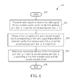
- FIG. 6 is a flowchart diagram of an antenna deployment determination processes 60 of the invention.
- the antenna deployment determination process 60 mainly focuses on the wireless communication device 10 including the first antenna port Ant_p- 1 and another second antenna port Ant_p- 2 .
- the antenna deployment determination processes 60 can be compiled to the program code 112 stored in the storage unit 110 of the wireless communication device 10 , and instructs the processing unit 100 to determine a condition of antenna deployment for the first antenna port Ant_p_ 1 and the second antenna port Ant_p_ 2 .
- the process 60 comprises the following steps:
- Step 600 Start.
- Step 602 Transmit radio signals or receive the radio signals from a wireless access point via the first antenna port Ant_p_ 1 and the second antenna port Ant_p_ 2 .
- Step 604 Obtain a first strength result and a second strength result corresponding to the radio signal transmitted or received via the first antenna port Ant_p_ 1 and the second antenna port Ant_p_ 2 , respectively.
- Step 606 Determine connecting statuses of the first antenna port Ant_p_ 1 and the second antenna port Ant_p_ 2 according to the first strength result and the second strength result.
- Step 608 End.
- the antenna deployment determination processes 60 is similar to the antenna deployment determination process 20 , and the only difference is that the antenna deployment determination process 60 mainly discusses the wireless communication device 10 including the first antenna port Ant_p_ 1 and the second antenna port Ant_p_ 2 . Accordingly, the radio signals are transmitted/received via the first antenna port Ant_p_ 1 and the second antenna port Ant_p_ 2 , such that the first strength result of the first antenna port Ant_p_ 1 and the second strength result of the second antenna port Ant_p_ 2 are utilized to determine the connecting statuses of the first antenna port Ant_p_ 1 and the second antenna port Ant_p_ 2 . Detailed operations are narrated in the following based on transmission or reception the wireless communication device 10 is performed. Certainly, those skilled in the art can adaptively modify the detailed steps of the antenna deployment determination process 60 to be applied to multiple antenna ports, which is also in the scope of the invention.
- the processing unit 100 performs transmitting the radio signals via the first antenna port Ant_p_ 1 and the second antenna port Ant_p_ 2 . If the radio signals are not configured to send to a distinct receiving terminal (e.g. to a wireless access point), the radio signals may be configured to be broadcast. After transmitting the radio signals, the processing unit 100 detects the strength levels of the radio signals transmitted via the first antenna port Ant_p_ 1 and the second antenna port Ant_p_ 2 , such that the first strength result and the second strength result corresponding to the first antenna port Ant_p_ 1 and the second antenna port Ant_p_ 2 are obtained, respectively.
- the processing unit 100 determines the condition of antenna deployment by determining the connecting statuses of the first antenna port Ant_p_ 1 and the second antenna port Ant_p_ 2 according to the first strength result and the second strength result.
- the first strength result and the second strength result may include transmitted signal strength indicator (TSSI) values corresponding to the first antenna port Ant_p_ 1 and the second antenna port Ant_p_ 2 , respectively, for the processing unit 100 to determine the connecting status.
- TSSI transmitted signal strength indicator
- FIG. 7 is a flowchart diagram of an antenna deployment determination process 70 according to an embodiment of the invention.
- the antenna deployment determination process 70 is performed in the transmission mode to be compiled to the program code 112 stored in the storage unit 110 of the wireless communication device 10 , and instructs the processing unit 100 to determine the condition of antenna deployment for the first antenna port Ant_p_ 1 and the second antenna port Ant_p_ 2 .
- the antenna deployment determination process 70 comprises the following steps:
- Step 700 Start.
- Step 702 Set the threshold.
- Step 704 Transmit radio signals via the first antenna port Ant_p_ 1 and the second antenna port Ant_p_ 2 .
- Step 706 Detect TSSI values corresponding to the first antenna port Ant_p_ 1 and the second antenna port Ant_p_ 2 .
- Step 708 Check whether one of the TSSI values corresponding the first antenna port Ant_p_ 1 or the second antenna port Ant_p_ 2 is larger than the absolute threshold.
- Step 710 Determining the connecting statuses of the first antenna port Ant_p_ 1 and the second antenna port Ant_p_ 2 .
- Step 712 End.
- the antenna deployment determination process 70 is similar to the antenna deployment determination process 40 . The only difference is that the antenna deployment determination process 70 is utilized for the first antenna port Ant_p_ 1 and the second antenna port Ant_p_ 2 . After the radio signals are transmitted, the processing unit 100 detects at least two the TSSI values corresponding to the first antenna port Ant_p_ 1 and the second antenna port Ant_p_ 2 , and accordingly, checks whether each TSSI value is larger than the threshold.
- the processing unit 100 determines that an antenna is attached to the antenna port Ant_p_ 1 ; otherwise, if the detected TSSI value corresponding to the antenna port Ant_p_ 1 is smaller than the absolute threshold, the processing unit 100 determines that no antenna is attached to the antenna port Ant_p_ 1 .
- the threshold may be determined according to different conditions, e.g., antenna types or external environments, which is no limiting to the scope of the invention.
- a plurality of predetermined thresholds may be set and stored in the storage unit 110 in advance for adaptive selection.
- those skilled in the art can adaptively modify the detailed steps of the processes 70 with additional thresholds to be applied to multiple antenna ports, which is also in the scope of the invention.
- an initial threshold and a relative threshold are set for the processing unit 100 to determine a condition of antenna deployment for the first antenna port Ant_p_ 1 and the second antenna port Ant_p_ 2 in the transmission mode.
- the initial threshold and the relative threshold can be derived from the threshold in the above embodiments to represent a comparison value in the embodiment, which is not limiting the scope of the invention.
- FIG. 8 is an exemplary flowchart diagram of an antenna deployment determination process 80 of the invention.
- the antenna deployment determination process 80 is performed in the transmission mode to be compiled to the program code 112 stored in the storage unit 110 of the wireless communication device 10 , and instructs the processing unit 100 to determine the condition of antenna deployment for the first antenna port Ant_p_ 1 and the second antenna port Ant_p_ 2 .
- the antenna deployment determination process 80 comprises the following steps:
- Step 800 Start.
- Step 802 Set the relative threshold and the initial threshold.
- Step 804 Transmit radio signals via the first antenna port Ant_p_ 1 and the second antenna port Ant_p_ 2 .
- Step 806 Detect TSSI values corresponding to the first antenna port Ant_p_ 1 and the second antenna port Ant_p_ 2 .
- Step 808 Reorder the TSSI values.
- Step 810 Check whether a first largest TSSI value among the detected TSSI values is larger than the initial threshold. If yes, go to Step 812 ; otherwise, go to Step 816 .
- Step 812 Check whether the difference between the first largest TSSI value and a second largest TSSI value among the detected TSSI values except the first largest TSSI value is smaller than the relative threshold. If yes, go to Step 814 ; otherwise, go to Step 816 .
- Step 814 Check whether there exists any TSSI value which is not checked. If yes, go to Step 812 ; otherwise, go to Step 816 .
- Step 816 Determine connecting statuses of the first antenna port Ant_p_ 1 and the second antenna port Ant_p_ 2 .
- Step 818 End.
- the wireless communication device 10 when the wireless communication device 10 starts to determine the condition of antenna deployment corresponding to the first antenna port Ant_p_ 1 and the second antenna port Ant_p_ 2 , the wireless communication device 10 sets the relative threshold and the initial threshold first, then transmits the radio signals via the first antenna port Ant_p_ 1 and the second antenna port Ant_p_ 2 . After the radio signals are transmitted, the processing unit 100 detects the TSSI values corresponding to the first antenna port Ant_p_ 1 and the second antenna port Ant_p_ 2 and reorders the TSSI values.
- the processing unit 110 checks whether a first largest TSSI value among the TSSI values is larger than the initial threshold. If the first largest TSSI value is not larger than the initial threshold, the processing unit 100 determines that no antenna is attached to the first antenna port Ant_p_ 1 and the second antenna port Ant_p_ 2 . Otherwise, if the first largest TSSI value is larger than the initial threshold, the processing unit 100 determines that an antenna is attached to an antenna port corresponding the first largest TSSI value, e.g. Ant_p_ 1 , and then checks whether the difference between the first largest TSSI value and a second largest TSSI value (i.e.
- the processing unit 100 determines that an antenna is attached to an antenna port corresponding to the second largest TSSI value, e.g. Ant_p_ 2 . If the difference between the first largest TSSI value and the second largest TSSI value is larger than the relative threshold, the processing unit 100 determines that an antenna is attached to the antenna port corresponding to the first largest TSSI value (i.e. Ant_p_ 1 ) and no antenna is attached to the antenna port corresponding to the second largest TSSI value (i.e. Ant_p_ 2 ).
- the connecting statuses of the first antenna port Ant_p_ 1 and the second antenna port Ant_p_ 2 can be determined via the processing unit 100 according the comparison between the first largest TSSI value, the second largest TSSI as well as the relative threshold and the initial threshold. Besides, if more antenna ports are existed, the processing unit 110 may continue to check whether the difference between the first largest TSSI value and a third largest TSSI value (i.e. the largest TSSI value among the TSSI values except the first and second largest TSSI values) is smaller than the relative threshold, so as to apply the embodiment for multiple ports, which is also in the scope of the invention.
- a third largest TSSI value i.e. the largest TSSI value among the TSSI values except the first and second largest TSSI values
- the initial/relative threshold may be determined according to different conditions, e.g., antenna types or external environments, and a plurality of predetermined initial/relative thresholds may be set and stored in the storage unit 110 in advance for adaptive selection.
- a plurality of predetermined initial/relative thresholds may be set and stored in the storage unit 110 in advance for adaptive selection.
- those skilled in the art can adaptively add/modify other operations/thresholds for the antenna deployment determination process 80 to be applied for multiple antenna ports, which is also in the scope of the invention.
- the processing unit 100 takes further actions, such as re-performing antenna deployment determination process again and notifying that an unusual condition happens, which can be applied to multiple antenna ports with the corresponding TSSI values being zero as well.
- the processing unit 100 performs receiving the radio signals via the first antenna port Ant_p_ 1 and the second antenna port Ant_p_ 2 .
- the radio signals from a wireless access point may be broadcast radio signals or sent to the wireless communication device 10 .
- the radio signals may be sent to another destination while being used by the wireless communication device 10 by a sniffing method.
- the processing unit 100 detects strength levels of the radio signals received via the first antenna port Ant_p_ 1 and the second antenna port Ant_p_ 2 , such that the first strength result and the second strength result corresponding to the first antenna port Ant_p_ 1 and the second antenna port Ant_p_ 2 are obtained.
- the processing unit 100 determines the condition of antenna deployment by determining the connecting statuses of the first antenna port Ant_p_ 1 and the second antenna port Ant_p_ 2 according to the first strength result and the second strength result.
- the first strength result and the second strength result may include received signal strength indicator (RSSI) values corresponding to the first antenna port Ant_p_ 1 and the second antenna port Ant_p_ 2 , so as to modify the antenna deployment determination process 70 for the reception mode in the following paragraph.
- RSSI received signal strength indicator
- FIG. 9 is a flowchart diagram of an antenna deployment determination process 90 according to an embodiment of the invention.
- the antenna deployment determination process 90 is performed in the reception mode to be compiled to the program code 112 stored in the storage unit 110 of the wireless communication device 10 , and instructs the processing unit 100 to determine the condition of antenna deployment for the first antenna port Ant_p_ 1 and the second antenna port Ant_p_ 2 .
- the antenna deployment determination process 90 comprises the following steps:
- Step 900 Start.
- Step 902 Set the threshold.
- Step 904 Receive radio signals via the first antenna port Ant_p_ 1 and the second antenna port Ant_p_ 2 from a wireless access point.
- Step 906 Detect RSSI values corresponding to the first antenna port Ant_p_ 1 and the second antenna port Ant_p_ 2 .
- Step 908 Check whether one of the RSSI values corresponding to the first antenna port Ant_p_ 1 and the second antenna port Ant_p_ 2 is larger than the absolute threshold.
- Step 910 Determine the connecting statuses of the first antenna port Ant_p_ 1 and the second antenna port Ant_p_ 2 .
- Step 912 End.
- the initial threshold and the relative threshold derived from the threshold in the above embodiments to represent a comparison value in the embodiment, are set for the processing unit 100 to determine the condition of antenna deployment for the first antenna port Ant_p_ 1 and the second antenna port Ant_p_ 2 in the reception mode.
- FIG. 10 is an exemplary flowchart diagram of an antenna deployment determination process 92 of the invention.
- the antenna deployment determination process 92 is performed in the reception mode to be compiled to the program code 112 stored in the storage unit 110 of the wireless communication device 10 , and instructs the processing unit 100 to determine the condition of antenna deployment for the first antenna port Ant_p_ 1 and the second antenna port Ant_p_ 2 .
- the antenna deployment determination process 92 comprises the following steps:
- Step 1000 Start.
- Step 1002 Set the initial threshold and the relative threshold.
- Step 1004 Receive radio signals via the first antenna port Ant_p_ 1 and the second antenna port Ant_p_ 2 from a wireless access point.
- Step 1006 Detect RSSI values corresponding to the first antenna port Ant_p_ 1 and the second antenna port Ant_p_ 2 .
- Step 1008 Reorder the RSSI values.
- Step 1010 Check whether a first largest RSSI value among the detected RSSI values is larger than the initial threshold. If yes, go to Step 1012 ; otherwise, go to Step 1016 .
- Step 1012 Check whether the difference between the first largest RSSI value and a second largest RSSI value among the detected RSSI values except the first largest RSSI value is smaller than the relative threshold. If yes, go to Step 1014 ; otherwise, go to Step 1016 .
- Step 1014 Check whether there exists any RSSI value which is not checked. If yes, go to Step 1012 ; otherwise, go to Step 1016 .
- Step 1016 Determine connecting statuses of the first antenna port Ant_p_ 1 and the second antenna port Ant_p_ 2 .
- Step 1018 End.
- processing unit 100 determines the connecting statuses of the first antenna port Ant_p_ 1 and the second antenna port Ant_p_ 2 according the comparison between the first largest RSSI value, the second largest RSSI value as well as the relative threshold and the initial threshold. Besides, if more antenna ports are existed, the processing unit 110 may continue to check whether the difference between the first largest RSSI value and a third largest RSSI value is smaller than the relative threshold, so as to apply the embodiment for multiple ports.
- those skilled in the art can adaptively add/modify other operations/thresholds for the antenna deployment determination process 92 to be applied for multiple antenna ports, which is also in the scope of the invention.
- the wireless communication device is capable of determining the connecting status for multiple antenna ports, such that the wireless communication device may determine optimized scheme accordingly for wireless transceiving.
- users of the invention can adaptively combine more than one wireless communication devices to increase the calculation efficiency, and the storage unit 110 of the wireless communication device 10 can predetermine separate/different programming codes corresponding to antenna deployment determination processes 20 , 40 , 50 , 60 , 70 , 80 , 90 and 92 , respectively, so as to reduce calculation periods of each process, which is also in the scope of the invention.
- a wireless communication device can determine a connecting status of antenna ports by software method, which is efficient and cost-effective.
Landscapes
- Engineering & Computer Science (AREA)
- Physics & Mathematics (AREA)
- Electromagnetism (AREA)
- Computer Networks & Wireless Communication (AREA)
- Signal Processing (AREA)
- Quality & Reliability (AREA)
- Telephone Function (AREA)
- Mobile Radio Communication Systems (AREA)
- Transceivers (AREA)
Abstract
Description
Claims (14)
Priority Applications (1)
| Application Number | Priority Date | Filing Date | Title |
|---|---|---|---|
| US13/666,991 US9692532B2 (en) | 2012-02-10 | 2012-11-02 | Method and wireless communication device for antenna deployment determination |
Applications Claiming Priority (2)
| Application Number | Priority Date | Filing Date | Title |
|---|---|---|---|
| US201261597186P | 2012-02-10 | 2012-02-10 | |
| US13/666,991 US9692532B2 (en) | 2012-02-10 | 2012-11-02 | Method and wireless communication device for antenna deployment determination |
Publications (2)
| Publication Number | Publication Date |
|---|---|
| US20130210368A1 US20130210368A1 (en) | 2013-08-15 |
| US9692532B2 true US9692532B2 (en) | 2017-06-27 |
Family
ID=48945975
Family Applications (1)
| Application Number | Title | Priority Date | Filing Date |
|---|---|---|---|
| US13/666,991 Active 2033-11-07 US9692532B2 (en) | 2012-02-10 | 2012-11-02 | Method and wireless communication device for antenna deployment determination |
Country Status (1)
| Country | Link |
|---|---|
| US (1) | US9692532B2 (en) |
Families Citing this family (5)
| Publication number | Priority date | Publication date | Assignee | Title |
|---|---|---|---|---|
| US9532252B2 (en) * | 2012-12-04 | 2016-12-27 | At&T Intellectual Property I, L.P. | Diagnosis of cellular network element states using radio frequency measurements |
| EP2787662B1 (en) * | 2013-04-05 | 2018-02-28 | Telefonaktiebolaget LM Ericsson (publ) | Antenna port detection |
| GB2516617B (en) * | 2013-06-12 | 2018-02-21 | Analog Devices Global | Communication unit or method for identifying a connectivity relationship between a logical channel and an antenna element of an active antenna system |
| CN113765533B (en) * | 2021-07-19 | 2023-07-04 | 上海闻泰信息技术有限公司 | Antenna detection method and device, electronic equipment and storage medium |
| US12408168B1 (en) * | 2022-04-28 | 2025-09-02 | Meta Platforms Technologies, Llc | Wireless configuration based on antenna connection status |
Citations (12)
| Publication number | Priority date | Publication date | Assignee | Title |
|---|---|---|---|---|
| US5617102A (en) * | 1994-11-18 | 1997-04-01 | At&T Global Information Solutions Company | Communications transceiver using an adaptive directional antenna |
| US6128470A (en) * | 1996-07-18 | 2000-10-03 | Ericsson Inc. | System and method for reducing cumulative noise in a distributed antenna network |
| US6339404B1 (en) * | 1999-08-13 | 2002-01-15 | Rangestar Wirless, Inc. | Diversity antenna system for lan communication system |
| US20060025081A1 (en) * | 2004-07-30 | 2006-02-02 | Alireza Zolfaghari | Transmitter signal strength indicator |
| US20070026827A1 (en) * | 2004-03-12 | 2007-02-01 | Kentaro Miyano | Wireless communication equipment and wireless communication method |
| US20070093282A1 (en) * | 2005-10-25 | 2007-04-26 | Henry Chang | Apparatus, system, and method for transmission antenna switching in a portable communication device |
| US20090131111A1 (en) * | 2007-11-21 | 2009-05-21 | Air Advantage | System and Method for Installatin of a Wireless Connection |
| US20100120415A1 (en) * | 2008-11-12 | 2010-05-13 | Nortel Networks Limited | Antenna auto-configuration |
| US7800553B2 (en) * | 2003-04-17 | 2010-09-21 | Fujitsu Limited | Information processing apparatus with antenna switching function, communication apparatus, antenna switching control unit, antenna switching control program, and computer-readable recording medium recording the same program |
| US20100311339A1 (en) * | 2009-06-05 | 2010-12-09 | Mediatek Inc. | System for the coexistence between a plurality of wireless communication modules |
| US7937052B2 (en) * | 2006-06-27 | 2011-05-03 | Cisco Technology, Inc. | Multiple input multiple output signal receiving apparatus with optimized performance |
| US8675762B2 (en) * | 2011-05-02 | 2014-03-18 | Alcatel Lucent | Method of transforming pre-coded signals for multiple-in-multiple-out wireless communication |
-
2012
- 2012-11-02 US US13/666,991 patent/US9692532B2/en active Active
Patent Citations (13)
| Publication number | Priority date | Publication date | Assignee | Title |
|---|---|---|---|---|
| US5617102A (en) * | 1994-11-18 | 1997-04-01 | At&T Global Information Solutions Company | Communications transceiver using an adaptive directional antenna |
| US6128470A (en) * | 1996-07-18 | 2000-10-03 | Ericsson Inc. | System and method for reducing cumulative noise in a distributed antenna network |
| US6339404B1 (en) * | 1999-08-13 | 2002-01-15 | Rangestar Wirless, Inc. | Diversity antenna system for lan communication system |
| US7800553B2 (en) * | 2003-04-17 | 2010-09-21 | Fujitsu Limited | Information processing apparatus with antenna switching function, communication apparatus, antenna switching control unit, antenna switching control program, and computer-readable recording medium recording the same program |
| US7353012B2 (en) * | 2004-03-12 | 2008-04-01 | Matsushita Electric Indutrial Co., Ltd. | Wireless communication equipment and wireless communication method |
| US20070026827A1 (en) * | 2004-03-12 | 2007-02-01 | Kentaro Miyano | Wireless communication equipment and wireless communication method |
| US20060025081A1 (en) * | 2004-07-30 | 2006-02-02 | Alireza Zolfaghari | Transmitter signal strength indicator |
| US20070093282A1 (en) * | 2005-10-25 | 2007-04-26 | Henry Chang | Apparatus, system, and method for transmission antenna switching in a portable communication device |
| US7937052B2 (en) * | 2006-06-27 | 2011-05-03 | Cisco Technology, Inc. | Multiple input multiple output signal receiving apparatus with optimized performance |
| US20090131111A1 (en) * | 2007-11-21 | 2009-05-21 | Air Advantage | System and Method for Installatin of a Wireless Connection |
| US20100120415A1 (en) * | 2008-11-12 | 2010-05-13 | Nortel Networks Limited | Antenna auto-configuration |
| US20100311339A1 (en) * | 2009-06-05 | 2010-12-09 | Mediatek Inc. | System for the coexistence between a plurality of wireless communication modules |
| US8675762B2 (en) * | 2011-05-02 | 2014-03-18 | Alcatel Lucent | Method of transforming pre-coded signals for multiple-in-multiple-out wireless communication |
Also Published As
| Publication number | Publication date |
|---|---|
| US20130210368A1 (en) | 2013-08-15 |
Similar Documents
| Publication | Publication Date | Title |
|---|---|---|
| US10924151B2 (en) | Transmitter device and transceiver device for transmitting different wireless standard signal | |
| US9692532B2 (en) | Method and wireless communication device for antenna deployment determination | |
| EP2454826B1 (en) | Diversity receiver and transceiver | |
| US8964737B2 (en) | Wireless communication circuit supporting antenna diversity | |
| US9130632B2 (en) | Diversity antenna system and transmission method | |
| US11510145B2 (en) | Wake-up radio | |
| US8942625B2 (en) | Communication device, control method, and program | |
| WO2018075139A1 (en) | Devices and methods for connecting wireless communication devices | |
| CN103187986A (en) | Wireless communication device | |
| US11309934B2 (en) | Method and apparatus for determining frequency hopping of channel, and computer storage medium | |
| WO2018166401A1 (en) | Method and apparatus for determining device beam reciprocity, and electronic device | |
| WO2018206082A1 (en) | Ue beam switching to backup beams for beam failure recovery | |
| US11962523B2 (en) | Method and apparatus for determining frequency hopping for a channel, and computer storage medium | |
| US12184588B2 (en) | Antenna optimization method in multiple connection environment and electronic device using same | |
| US9276624B2 (en) | Antenna system with self-identifying antenna | |
| CN114531173B (en) | Multi-antenna frequency division duplex mode terminal receiving sensitivity optimization method and device and terminal equipment | |
| CN107689805A (en) | Radio frequency amplification method and device based on TDD mode of operations | |
| KR102927107B1 (en) | Electronic device and method for controlling setting of annenna in the electronic device comprising a plurality of antennas | |
| CN112218311B (en) | Method for improving overall transmission rate of mesh network and related equipment | |
| US20140362932A1 (en) | Communication apparatus, communication system, communication method, and storage medium | |
| US9998189B1 (en) | Adaptive device and method for wireless network | |
| US12232045B2 (en) | Communication apparatus, communication method, and program | |
| CN210867766U (en) | Radar system | |
| CN113507291B (en) | Signal processing method, device, computer equipment and storage medium | |
| CN121263963A (en) | Electronic device comprising an antenna |
Legal Events
| Date | Code | Title | Description |
|---|---|---|---|
| AS | Assignment |
Owner name: RALINK TECHNOLOGY CORP., TAIWAN Free format text: ASSIGNMENT OF ASSIGNORS INTEREST;ASSIGNORS:LEE, YU-JU;TSAI, CHENG-LUNG;HSU, HAO-SHENG;AND OTHERS;REEL/FRAME:029230/0286 Effective date: 20121101 |
|
| AS | Assignment |
Owner name: MEDIATEK INC., TAIWAN Free format text: MERGER;ASSIGNOR:RALINK TECHNOLOGY CORP.;REEL/FRAME:033291/0551 Effective date: 20140401 |
|
| STCF | Information on status: patent grant |
Free format text: PATENTED CASE |
|
| MAFP | Maintenance fee payment |
Free format text: PAYMENT OF MAINTENANCE FEE, 4TH YEAR, LARGE ENTITY (ORIGINAL EVENT CODE: M1551); ENTITY STATUS OF PATENT OWNER: LARGE ENTITY Year of fee payment: 4 |
|
| MAFP | Maintenance fee payment |
Free format text: PAYMENT OF MAINTENANCE FEE, 8TH YEAR, LARGE ENTITY (ORIGINAL EVENT CODE: M1552); ENTITY STATUS OF PATENT OWNER: LARGE ENTITY Year of fee payment: 8 |