US968743A - Liquid measuring and vending device. - Google Patents
Liquid measuring and vending device. Download PDFInfo
- Publication number
- US968743A US968743A US39950307A US1907399503A US968743A US 968743 A US968743 A US 968743A US 39950307 A US39950307 A US 39950307A US 1907399503 A US1907399503 A US 1907399503A US 968743 A US968743 A US 968743A
- Authority
- US
- United States
- Prior art keywords
- valve
- passage
- lever
- arm
- water
- Prior art date
- Legal status (The legal status is an assumption and is not a legal conclusion. Google has not performed a legal analysis and makes no representation as to the accuracy of the status listed.)
- Expired - Lifetime
Links
Images
Classifications
-
- G—PHYSICS
- G07—CHECKING-DEVICES
- G07F—COIN-FREED OR LIKE APPARATUS
- G07F11/00—Coin-freed apparatus for dispensing, or the like, discrete articles
- G07F11/02—Coin-freed apparatus for dispensing, or the like, discrete articles from non-movable magazines
- G07F11/04—Coin-freed apparatus for dispensing, or the like, discrete articles from non-movable magazines in which magazines the articles are stored one vertically above the other
- G07F11/16—Delivery means
- G07F11/24—Rotary or oscillatory members
Definitions
- Our invention relates to an improved liquid measuring and vending device adapted to deliver measured quantities of liquid in exchange for a coin; and it consists in the measuring and vending device described in the following specification, illustrated in the accompanying drawings, and particularly defined in the clauses of the concluding claim.
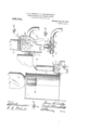
- FIG. 1 is a view of our device in elevation and attached to a suitable water cooler, a portion of the water cooler being broken away to show the interior construction thereof and the means whereby a constant level of liquid is maintained therein
- FIG. 2 is an enlarged view showing our device more in detail
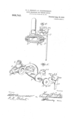
- Fig. 3 is a sectional view through a rotary valve tormin a part of our device
- Fig. 4 is a section [alien upon the line l l of Fig. .2, certain elements being omitted for the sake of clearness oi illustration. the conduit l and the parts of the valve casing adjacent thereto being also shown.
- Fig. 5 is a perspective view oi the valve and operating means therefor, the parts being shown separated.
- Our in'iprovcd liquid measuring and vcnding device is designed to:- use in connection with and tor measuring and vending water or other beverage from a, cooler supplied fron'i an inverted bottle, and in which cooler a constant. l vel oi" liquid is maintained, and in Fig. l the ret'crc21.-e chanurtrr l indi ates toe (internal easing of such a cooler and 2 an inverted bottle containing a supply of liquid.
- the level of the liquid being maintained at about the level indicated by the 3 is a valve casing having a supply conduit 4 leading from a source of supply, and a discharge conduit terminating in a. spout 5.
- (3 is a measuring vessel made preferably of glass and having an opening at its upper end as at 7 whereby said measuring vessel will always be in open communication with the surrounding atmosphere; and this measuring vessel is connected withthe valve casing 3 by the conduit 8 which conduit also preferably serves nring glass.
- valve 9 is a rotary valve located within the as a support for the ineasvalve casing 3, and 10 and 11 are ports in' communication with one another by means of a passage extending through the rotary valve and which are adapted to i'egistcrnv'itli the ports 12 and 13 thereby establishing connnunication between the supply conduit 4 and the conduit 8 leading to the measuring vessel (3; or, as illnstratcl'l in Fig. 3, to register with ports 13 and 14, thereby establishing COlllll'lLlIllCtltlOll between the measuring vessel and the discharge/spout 5.
- V The valve 9 is normally inthc; position shown in Fig.
- valve 15 is an arm rigidly secured to the valve t) and by means of which said valve maybe rotated, and iii is a spindle projecting from the valve.
- 1.7 is an operating lever for rotating the valvc 9.
- This lever is provided with a bearing 18 by means of which it is supported by and normally tree to move about the spindle 10 as an axis and without rotatii'ig the valve .3, but the said lever and valve may be connected together in the manner hereinafter described so that movement imparted to the lever will rotatethe valve through the arm 15.
- the (narrating lever 17 is provided with a shelf-like portion 19 adjacent the bearing 18 for receiving and supporting a coin which shelf portionis provided with a slot .20 and with one or more holes "ll, 21.
- the arm 15 is provided with a lug which is bent over so as to extendparallel with and at a short distance from the shelf portion 19 of the lever 17, and said lug is so designed and positioned upon the arm that it may pass through the slot- 20 of the shelf portion 19 when the lever 17 is operated, as will be understoodfrom Fig. a of the drawings.
- the arm 15 is also provided with a second lug 23 similar to but shorter than the lug 22, which lug is adapted to be engaged by the upper portion. 24 of the shelf portion 19, whereby the arm may be moved to the right (Figs 2 and 5) by the lever 17.
- 27, 27 are pins carried by the stop 25 and projecting through the holes 21, 21, when the parts are assembled.
- Our device is intended to be used as a coin controlled liquid vending device as above stated; to which end. we surround the operating mechanism for the valve with a casing 29 having a slot 30 in which the op erating lever 17 works, a chute 31 through which a coin may be supplied, and a passage way 32 shown broken away but designed to lead to a suitable box for receiving the coins.
- a cooling chamber means for maintaining a constant level of desire to secure by Letters water in said cooling chamber; a measuring vessel the upper end of which extends above the level of water in said cooling chamber and which measuring vessel is in'open communication with the atmosphere; a valve casing having supply and discharge pas 8o charge passage, according to the position into which said valve may be moved, to thereby control the how of water through the passages in said valve casing; an arm secured to said rotary valve and through which said valve may be rotated; a spindle projecting from said valve; a lever supported by and :free to move upon saidv spindle as an axis; a stop carried by said 'alve casing and serving to limit the movement of said lever in one direction; means whereby said lever and arm may be connected together to thereby rotate said arm and valve in one direction; and means carried by said arm and engaged by said lever for rotating said arm and valve in a reverse direction.
- a cooling chamber In a water cooler, a cooling chamber; means for maintaining a constant level of water in said cooling chamber; a valve easing having supply and discharge passages,
- a conduit connecting said cooling chamber with the supply passage f said-valve casing; a rotary valve within said casing and having a passagewh ch passage may 'estab.
- a cooling chamber means for maintaining a constant level of water in said cooling chamber; a measuring vessel the upper end of whichextends above the level of water in said cooling chamber and which measuring vessel is in open communication with the atmosphere; a valve casing having a normally closed supply passage and a normally open discharge passage, and having also a third passage through which water imay flow to said measuring vessel; a conduit connecting said cooling chamber with the supply passage of said valve casing; a rotary valve within said casing and having a passage which passage may establishcommunication between said third passage and said supply passage or between said third passage and said discharge passage, according to the position be moved to thereby control the flow of water through the passages in said valve casing; an arm secured to said rotary valve and through which said valve may be rotated; a spindle projecting from said valve; a lever supported by and free to move upon said spindle as an axis; a stop for limiting the movement of said lever in one direction: means wherel'iy said lever and arm may be connected
- a water cooler a cooling chamber; means for maintaining"E a constant level of water in said cooling chan'iber; a n'ieasuring vessel the upper end ot; which extends above the level of water in said cooling chamber and which measuring vessel is in open com munication with the atmosphere; a valve casing having a normally closed supply passage and a normally open discharge passage and having also a third passage through which water may flow to said measuring vessel a conduit connecting said cooling chamber with the supply passage of said valve casing; a rotarywalve within said casing and having a passage which passage may establish connmmication between said third passage and said supply passage or between said third passage and said discharge passage, according to the position into which said valve may be moved, to thereby control the flow of water through the passages in said valve casing; an arm secured to said rotary valve and through which said valve may be rotated; an operating lever adapted to rotate said valve; a stop for limiting the movement of said lever in one direction; means whereby said love and arm may
- a cooling chamber In a water cooler, a cooling chamber; means for maintaining a constant level of, water in said cooling chamber; a measuring vessel the upper end of which extends above the-level of water in said cooling chamber and which measuring vessel is in open communication with the atmosphere; a valve casing having a normally closed supply passage and a normally open discharge passage and having also a third passage through which water may flow to said measuring vessel; a conduit connecting said cooling chamber with the supply passage of said valve casing; a rotary valve within said casing and having a passage which passage may establish communication between said third passage and said supply passage or be tween said third passage and said discharge passage, according to the positioninto which said valve may be moved, to thereby control the flow of water through the passages in said valve casing; an arm secured to said rotary valve and through which said valve may be rotated; an operating lever adapted to move about the axis of said rotary valveand-through which said valve may be 0-,'
- a cooling chamber In a water cooler, a cooling chamber; means for maintaining a constant; level of water in said cooling chamber; a valve casing having supply and discharge passages, andhaving also a third passage; a conduit communicating with said third passage and extending upwardly therefrom; a measuring vessel independent of said valve casing Y water in said cooling chamber; a valve casand supported by said conduit, the upper end of which measuring vessel extends above the level or" water in said cooling chamber and which measuring vessel is in open communication with the atmosphere; a conduitconnecting said cooling chamber with the supply passage of said valve casing; a rotary valve within said casing and having a passage whichpassage may establish communication between said third passage and said supply passage or between said third passage and said discharge passage, accord ing to the position into which said valve may be moved, to thereby control the flow of water through the passages in said valve casing; an arm secured to said.
- a cooling chamber In a water cooler, a cooling chamber; means for maintammg a constant level of ing having supply and discharge passages, and having also a third passage; a conduit communicating with said third passage and extending upwardly therefrom; a measuring vessel independent of said valve casing and supported by said conduit, the upper end of which measuring vessel extends above the level of Water in said cooling chamber and which measuring vessel'is in open communication with the atmosphere; a conduit connecting said cooling chamber with the supply passage of said valve casing; a ro taryvalve within said casing and having a passage which passage may establish communication betweensaid third. passage and said supply passage or between said third? assa e and said dischare assa e'.
- valve casing having supply and discharge passages, and having also a third passage through which water may flow to said measuring vessel; a conduit connecting said cooling chamber withthe supplypassage of said valve casing; a rotary valve within said casing and having a passage which passage may establish communication between said third passage andv said supply passage or between said third passage and said discharge passage, according to the position into which said valve may be moved, to
Landscapes
- Physics & Mathematics (AREA)
- General Physics & Mathematics (AREA)
- Devices For Dispensing Beverages (AREA)
Description
H. G. CORDLEY dz E. KLEINSGHMIDT. LIQUID MEASURING AND VENDING DEVICE. APPLICATION FILED OCT. 28, 1907.
2 SHEETS-SHEET 1.
mueufom Patented Aug. 30, 1910.
H. G. OORDLEY & E. KLBINSOHMIDT.
SURING AND VENDING DEVICE.-
LIQUID MBA APPLICATION FILED 0GT.28, 1907.
Patented Aug. 30, 1910.
2 SHEETS-SHEET 2.
tin'rrn stares arrest nine.
HENRY G. CORDLEY, OF GLEN RIDGE, NEW JERSEY, AND EDWARD KLEIHSCHMIDT, OF NEW YORK, N. Y., ASSIGNORS T0 HENRY G. CORDLEY, 0F GLEN RIDGE, NEW
JERSEY.
LIQUID MEASURING AND VENDING DEVICE.
Patented Aug. 30, 191.0.
Application filed October 28, 1907. Serial No. 399,503.
1'0 all whom it may concern: v
Be it known that we, llnxnv Gr. Couoiaiv,
a citizen of the United States, residing at the accom )anvin drawin 's formin at )art hereof.- 7
Our invention relates to an improved liquid measuring and vending device adapted to deliver measured quantities of liquid in exchange for a coin; and it consists in the measuring and vending device described in the following specification, illustrated in the accompanying drawings, and particularly defined in the clauses of the concluding claim.
in the accompanying drawings; Figure l is a view of our device in elevation and attached to a suitable water cooler, a portion of the water cooler being broken away to show the interior construction thereof and the means whereby a constant level of liquid is maintained therein, Fig. 2 is an enlarged view showing our device more in detail, Fig. 3 is a sectional view through a rotary valve tormin a part of our device, Fig; 4 isa section [alien upon the line l l of Fig. .2, certain elements being omitted for the sake of clearness oi illustration. the conduit l and the parts of the valve casing adjacent thereto being also shown. and, Fig. 5 is a perspective view oi the valve and operating means therefor, the parts being shown separated.
Our in'iprovcd liquid measuring and vcnding device is designed to:- use in connection with and tor measuring and vending water or other beverage from a, cooler supplied fron'i an inverted bottle, and in which cooler a constant. l vel oi" liquid is maintained, and in Fig. l the ret'crc21.-e chanurtrr l indi ates toe (internal easing of such a cooler and 2 an inverted bottle containing a supply of liquid. the level of the liquid being maintained at about the level indicated by the 3 is a valve casing having a supply conduit 4 leading from a source of supply, and a discharge conduit terminating in a. spout 5.
(3 is a measuring vessel made preferably of glass and having an opening at its upper end as at 7 whereby said measuring vessel will always be in open communication with the surrounding atmosphere; and this measuring vessel is connected withthe valve casing 3 by the conduit 8 which conduit also preferably serves nring glass.
9 is a rotary valve located within the as a support for the ineasvalve casing 3, and 10 and 11 are ports in' communication with one another by means of a passage extending through the rotary valve and which are adapted to i'egistcrnv'itli the ports 12 and 13 thereby establishing connnunication between the supply conduit 4 and the conduit 8 leading to the measuring vessel (3; or, as illnstratcl'l in Fig. 3, to register with ports 13 and 14, thereby establishing COlllll'lLlIllCtltlOll between the measuring vessel and the discharge/spout 5. V The valve 9 is normally inthc; position shown in Fig. 3, so that the measuring vessel (3 is normally in communication with the discharge spout. Said valve is, however, in the operation of the device, rotated by mechanism hereinafter to be described soas to establish comniunicationbetween the source of supply and the measuring vessel.
15 is an arm rigidly secured to the valve t) and by means of which said valve maybe rotated, and iii is a spindle projecting from the valve.
1.7 is an operating lever for rotating the valvc 9. This lever is provided with a bearing 18 by means of which it is supported by and normally tree to move about the spindle 10 as an axis and without rotatii'ig the valve .3, but the said lever and valve may be connected together in the manner hereinafter described so that movement imparted to the lever will rotatethe valve through the arm 15. The (narrating lever 17 isprovided with a shelf-like portion 19 adjacent the bearing 18 for receiving and supporting a coin which shelf portionis provided with a slot .20 and with one or more holes "ll, 21.
The arm 15 is provided with a lug which is bent over so as to extendparallel with and at a short distance from the shelf portion 19 of the lever 17, and said lug is so designed and positioned upon the arm that it may pass through the slot- 20 of the shelf portion 19 when the lever 17 is operated, as will be understoodfrom Fig. a of the drawings. The arm 15 is also provided with a second lug 23 similar to but shorter than the lug 22, which lug is adapted to be engaged by the upper portion. 24 of the shelf portion 19, whereby the arm may be moved to the right (Figs 2 and 5) by the lever 17.
25 is a stop supported from the valve casing 3 by means of a bracket 26 and against which the shelf portion 19 rests, as will be understood from Figs. 2 and 5.
27, 27 are pins carried by the stop 25 and projecting through the holes 21, 21, when the parts are assembled.
28 is a pin carried by the bearing 18 and which engages with the stop to limit the movement of the operating lever when the valve 9 is operated.
Our device is intended to be used as a coin controlled liquid vending device as above stated; to which end. we surround the operating mechanism for the valve with a casing 29 having a slot 30 in which the op erating lever 17 works, a chute 31 through which a coin may be supplied, and a passage way 32 shown broken away but designed to lead to a suitable box for receiving the coins.
and are stops placed upon the shelf 19 to guide and maintain the coin in proper position.
Our device operates as follows: A coin upon being placed in the chute 31 slides down between the stops 33 and 3% on to the shelf portion 19 and beneath the lug 22 until it comes to rest against the pins 27 as indicated in dotted lines in Fig. l, The operating lever 17 is now moved in the direction of the arrow, Fig. 2, whereupon the coin will.
be brought into engagement with the lug 22 of the arm 15, the pins 27 still maintaining the coin in proper position. Further movement of the operating lever will now rotate the valve 9' into position such that the ports 10 and 11 will register with the ports 12 and 18, the coin meanwhile having been carried beyond the pins 27. The operating lever havin now reached its extreme posit-ion, liquid Wlll flow through the conduits 4: and 8 into the measuring glass (5 until the level therein corresponds with the level of the liquid in the cooler 1. The operating lever 17 is now .moved in the reverse direction, whereupon the coin will be released and will fall from the shelf 19 and pass through the passage way 32 into a suitable box. During the return movement of the lever 17 the upper portion 2% of the shelf portion 1?) engages with the lug 23 of the arm. 15 to thereby rotate the valv 9 back into its original position as indicated in Fig. 3. The liquid 5 in the measurn vessel (3 is now free to flow therefrom through the conduit 8 and spout 5 into a suitable receptacle.
Having thus described our invention and explained the mode of operation thereof, we
claim and Patent:
1. In a water cooler, a cooling chamber; means for maintaining a constant level of desire to secure by Letters water in said cooling chamber; a measuring vessel the upper end of which extends above the level of water in said cooling chamber and which measuring vessel is in'open communication with the atmosphere; a valve casing having supply and discharge pas 8o charge passage, according to the position into which said valve may be moved, to thereby control the how of water through the passages in said valve casing; an arm secured to said rotary valve and through which said valve may be rotated; a spindle projecting from said valve; a lever supported by and :free to move upon saidv spindle as an axis; a stop carried by said 'alve casing and serving to limit the movement of said lever in one direction; means whereby said lever and arm may be connected together to thereby rotate said arm and valve in one direction; and means carried by said arm and engaged by said lever for rotating said arm and valve in a reverse direction.
2. In a water cooler, a cooling chamber; means for maintaining a constant level of water in said cooling chamber; a valve easing having supply and discharge passages,
and having also a third passage; a conduit communicating with said third passage and extending upwardly therefrom; a measuring vessel independent of said valve casing and supported by said conduit, the upper end of which measuring vessel extends above the level of water in said cooling chamber and which measuring vessel is in open communication with the atmosphere;
a conduit connecting said cooling chamber with the supply passage f said-valve casing; a rotary valve within said casing and having a passagewh ch passage may 'estab.
lish communication between said third passage and said supply passage or between said third passage and discharge passage, according to the position into which said valve may moved, to therebv control the a rotary valve within said 85 into whiclnsaid valve may flow of vater through the passages in said valve casing; an arm secured to said rotary valve and through which said valve may be rotated; a spindle projecting from said valve; a lever supported by and tree to move upon said spindle as an axis; a stop for limiting the movement of said lever in one direction; means whereby said lever and arm may be connected together to thereby rotate said valve in one direction; and
means carried by said arm and engaged by said lever to thereby rotate said valve in a reverse direction.
3. In a watencooler, a cooling chamber; means for maintaining a constant level of water in said cooling chamber; a measuring vessel the upper end of whichextends above the level of water in said cooling chamber and which measuring vessel is in open communication with the atmosphere; a valve casing having a normally closed supply passage and a normally open discharge passage, and having also a third passage through which water imay flow to said measuring vessel; a conduit connecting said cooling chamber with the supply passage of said valve casing; a rotary valve within said casing and having a passage which passage may establishcommunication between said third passage and said supply passage or between said third passage and said discharge passage, according to the position be moved to thereby control the flow of water through the passages in said valve casing; an arm secured to said rotary valve and through which said valve may be rotated; a spindle projecting from said valve; a lever supported by and free to move upon said spindle as an axis; a stop for limiting the movement of said lever in one direction: means wherel'iy said lever and arm may be connected together to thereby rotate said valve in one direction to close said discharge passage and to open said supply passage; aml'mcans carried by said arm and engaged by said lever to thereby rotate said valvein a reverse'direction to close said supply passage and open said dischar b passage.
4. ln a water cooler; a cooling chamber; means for maintaining"E a constant level of water in said cooling chan'iber; a n'ieasuring vessel the upper end ot; which extends above the level of water in said cooling chamber and which measuring vessel is in open com munication with the atmosphere; a valve casing having a normally closed supply passage and a normally open discharge passage and having also a third passage through which water may flow to said measuring vessel a conduit connecting said cooling chamber with the supply passage of said valve casing; a rotarywalve within said casing and having a passage which passage may establish connmmication between said third passage and said supply passage or between said third passage and said discharge passage, according to the position into which said valve may be moved, to thereby control the flow of water through the passages in said valve casing; an arm secured to said rotary valve and through which said valve may be rotated; an operating lever adapted to rotate said valve; a stop for limiting the movement of said lever in one direction; means whereby said love and arm may be connected together to thereby rotate said valve in one direction to close said discharge passage and to open said supply passage; and means carried by said arm and engaged by said lever to thereby rotate said valve in areverse direction to close said supply passage and open said discharge passage.
In a water cooler, a cooling chamber; means for maintaining a constant level of, water in said cooling chamber; a measuring vessel the upper end of which extends above the-level of water in said cooling chamber and which measuring vessel is in open communication with the atmosphere; a valve casing having a normally closed supply passage and a normally open discharge passage and having also a third passage through which water may flow to said measuring vessel; a conduit connecting said cooling chamber with the supply passage of said valve casing; a rotary valve within said casing and having a passage which passage may establish communication between said third passage and said supply passage or be tween said third passage and said discharge passage, according to the positioninto which said valve may be moved, to thereby control the flow of water through the passages in said valve casing; an arm secured to said rotary valve and through which said valve may be rotated; an operating lever adapted to move about the axis of said rotary valveand-through which said valve may be 0-,'
tated;'a stop for limiting the movement I 5 said lever in one direction; means whereby said lever and arm may be connected together to thereby rotate said valve in one direction to close said discharge passage and i.
to open said supply passage; and means carried by said arm and engaged by said lever to thereby rotate said valve in areverse direction to close said supply passage and open said discharge passage.
(3. In a water cooler, a cooling chamber; means for maintaining a constant; level of water in said cooling chamber; a valve casing having supply and discharge passages, andhaving also a third passage; a conduit communicating with said third passage and extending upwardly therefrom; a measuring vessel independent of said valve casing Y water in said cooling chamber; a valve casand supported by said conduit, the upper end of which measuring vessel extends above the level or" water in said cooling chamber and which measuring vessel is in open communication with the atmosphere; a conduitconnecting said cooling chamber with the supply passage of said valve casing; a rotary valve within said casing and having a passage whichpassage may establish communication between said third passage and said supply passage or between said third passage and said discharge passage, accord ing to the position into which said valve may be moved, to thereby control the flow of water through the passages in said valve casing; an arm secured to said. rotary valve and through which said valve may be rotated;-an operating lever adapted to rotate said valve; a stop for limiting the movement of said lever in one direction; means whereby said lever and arm may be connected together to thereby rotate said valve in one direction; and means carried by "said arm and engaged by said lever to thereby rotate said valve in a reverse direction. 7. In a water cooler, a cooling chamber; means for maintammg a constant level of ing having supply and discharge passages, and having also a third passage; a conduit communicating with said third passage and extending upwardly therefrom; a measuring vessel independent of said valve casing and supported by said conduit, the upper end of which measuring vessel extends above the level of Water in said cooling chamber and which measuring vessel'is in open communication with the atmosphere; a conduit connecting said cooling chamber with the supply passage of said valve casing; a ro taryvalve within said casing and having a passage which passage may establish communication betweensaid third. passage and said supply passage or between said third? assa e and said dischare assa e'. accordingto the position into which said valve may be moved, to thereby control the flow of water through the passages in said valve casing; an arm secured'to said rotary valve and through which said valve may be roeeavae tated; an operating lever adapted to move about the axis of said rotary valve and through which said valve may be operated; a stop for limiting the movement of said lever in one direction; means whereby said.
open communication with the atmosphere;
a valve casing having supply and discharge passages, and having also a third passage through which water may flow to said measuring vessel; a conduit connecting said cooling chamber withthe supplypassage of said valve casing; a rotary valve within said casing and having a passage which passage may establish communication between said third passage andv said supply passage or between said third passage and said discharge passage, according to the position into which said valve may be moved, to
thereby control the flow of Water through the passages'in said valve casing; an arm secured to said rotary valve and through which said valve may be rotated; an oper- I ating lever adapted to rotate said valve; a stop carried by said valve casin and serving to limit the movement ofsald lever in one direction; means whereby said lever and I arm may be connected together to thereby rotate said arm" and valve and meanscarried by said armand engaged in. one direction;
by said lever for rotating said arm and valve in a reverse direction.
This specification signed and ivitnessed this 23rd dayof October A'. D. 19071. HENRYGICORDLEY,
EDWARD KLEINSOHMIDT, In the presence of; I J. B.- Konnooernn, l LEAVELL.
Priority Applications (1)
| Application Number | Priority Date | Filing Date | Title |
|---|---|---|---|
| US39950307A US968743A (en) | 1907-10-28 | 1907-10-28 | Liquid measuring and vending device. |
Applications Claiming Priority (1)
| Application Number | Priority Date | Filing Date | Title |
|---|---|---|---|
| US39950307A US968743A (en) | 1907-10-28 | 1907-10-28 | Liquid measuring and vending device. |
Publications (1)
| Publication Number | Publication Date |
|---|---|
| US968743A true US968743A (en) | 1910-08-30 |
Family
ID=3037133
Family Applications (1)
| Application Number | Title | Priority Date | Filing Date |
|---|---|---|---|
| US39950307A Expired - Lifetime US968743A (en) | 1907-10-28 | 1907-10-28 | Liquid measuring and vending device. |
Country Status (1)
| Country | Link |
|---|---|
| US (1) | US968743A (en) |
-
1907
- 1907-10-28 US US39950307A patent/US968743A/en not_active Expired - Lifetime
Similar Documents
| Publication | Publication Date | Title |
|---|---|---|
| US674685A (en) | Steam cooking apparatus. | |
| US637238A (en) | Coin-freed delivery apparatus. | |
| US2545614A (en) | Multibeverage vending machine | |
| US762429A (en) | Coin-operated liquid-vending machine. | |
| US1103952A (en) | Check-controlled apparatus. | |
| US624844A (en) | moser | |
| US846366A (en) | Coin-controlled liquid-vending apparatus. | |
| US1070917A (en) | Liquid-measuring appliance. | |
| US1418770A (en) | Register | |
| US412127A (en) | Henri scitloesing and benjamin degremont | |
| US1125000A (en) | Prepayment-meter mechanism. | |
| US988570A (en) | Coin-controlled machine. | |
| US447594A (en) | Henry b | |
| US611225A (en) | Machine for vending liquids | |
| US565383A (en) | Automatic gas-vending apparatus | |
| US618802A (en) | phillips | |
| US690475A (en) | Coin-controlled liquid-vending machine. | |
| US1861227A (en) | Beverage mixer and dispenser | |
| US663338A (en) | Prepayment vending appliance. | |
| US1860028A (en) | Dispensing machine for bottled goods | |
| US763645A (en) | Coin-controlled liquid-vending apparatus. | |
| US546265A (en) | williams | |
| US835520A (en) | Molten-metal-measuring apparatus. | |
| US454407A (en) | silkman | |
| US653488A (en) | Coin-controlled vending-machine. |