US968700A - Flying apparatus. - Google Patents
Flying apparatus. Download PDFInfo
- Publication number
- US968700A US968700A US37723207A US1907377232A US968700A US 968700 A US968700 A US 968700A US 37723207 A US37723207 A US 37723207A US 1907377232 A US1907377232 A US 1907377232A US 968700 A US968700 A US 968700A
- Authority
- US
- United States
- Prior art keywords
- wings
- wing
- air
- quill
- stroke
- Prior art date
- Legal status (The legal status is an assumption and is not a legal conclusion. Google has not performed a legal analysis and makes no representation as to the accuracy of the status listed.)
- Expired - Lifetime
Links
- 235000014101 wine Nutrition 0.000 description 3
- 230000001174 ascending effect Effects 0.000 description 2
- 239000000969 carrier Substances 0.000 description 2
- 230000000694 effects Effects 0.000 description 2
- 210000003746 feather Anatomy 0.000 description 2
- 239000000463 material Substances 0.000 description 2
- 230000000153 supplemental effect Effects 0.000 description 2
- 241000947840 Alteromonadales Species 0.000 description 1
- 241000612703 Augusta Species 0.000 description 1
- 244000088401 Pyrus pyrifolia Species 0.000 description 1
- 238000010276 construction Methods 0.000 description 1
- 238000010586 diagram Methods 0.000 description 1
- 239000004744 fabric Substances 0.000 description 1
- 230000001141 propulsive effect Effects 0.000 description 1
- 230000013707 sensory perception of sound Effects 0.000 description 1
Images
Classifications
-
- F—MECHANICAL ENGINEERING; LIGHTING; HEATING; WEAPONS; BLASTING
- F04—POSITIVE - DISPLACEMENT MACHINES FOR LIQUIDS; PUMPS FOR LIQUIDS OR ELASTIC FLUIDS
- F04D—NON-POSITIVE-DISPLACEMENT PUMPS
- F04D25/00—Pumping installations or systems
- F04D25/02—Units comprising pumps and their driving means
- F04D25/08—Units comprising pumps and their driving means the working fluid being air, e.g. for ventilation
- F04D25/10—Units comprising pumps and their driving means the working fluid being air, e.g. for ventilation the unit having provisions for automatically changing direction of output air
- F04D25/105—Units comprising pumps and their driving means the working fluid being air, e.g. for ventilation the unit having provisions for automatically changing direction of output air by changing rotor axis direction, e.g. oscillating fans
Definitions
- the apparatus for aerial. navigation ac- .cording to this invention is elnirarterized by the peculiar construction and operation of wings, whioli are arranged in groups or sets on rotary elements re ⁇ "olving like wheels atthe frame-sides of the aerial maehine'.
- the wings are adjusted automatically so as to drive away the air after the manner of paddle wheels and to att'ord the etl'ertive propolling and ascending power for the machine while sinniltaueously yielding the 'eond-ary advantages of an aeroplane i'inwhine.
- the wing formingpart of the suhject ot the present invention is essentially a flapping wing that to say, on the downstroke it beats the air with a hlow, and on the upstroke it moves through the air idly, with little or no tendenoy to depress the machine or act counter to its downstroke.
- wing which of spoon shaped or concave-convex form provided with strips constituting valve llaps adapted to open only toward the concave, or under side, and the wings are arranged in groups and are so actuated that on both the downstroke and the upstroke the concave side of the wing will he downward, while on the downstroke the rearward part of the wing will he tilted somewhat in the manner ahove referred to.
- wing is adapted to attain both liittii'ig and propulsive etteets.
- Another feature of the wings consists in providing same at their outer ends with elastic blades or anes corresponding with the primary wing feathers of a bird and so devised that the air ean escape idly past them on their upstroke while on their down stroke they resist the upward escape of the air and moreover cause same to par-s rearwardly (that is to say, longitudiinilly ot the Wing) so as to facilitate propulsion.
- the car is closed on its upper side and .tapers to the tront and to the rear; and on the. said upper side there are provided longitudinal guiding surfaces: or his adapted to steady the flight.
- the dying machine is Specification of Letters Patent.
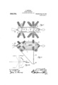
- t-L are plan and side elevation reapectively ot a oonstruetional form of the flying apparatus.
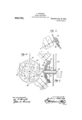
- Figs. 3i) show the gear ot the apparatus between the shaft and wing rod.
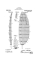
- Fig. C is a perspective View showing diagramiuatically the arrangcinent of the parts of one of the wings; Pig. 7 is a plan o t the wine on an enlarged scale; Fig. 8 is a hmgitudinal section of same; Fig.1) is a detail ot the Supplemental hlade arranged at the ends of th wings similar to a. hirds outermost with feathers;
- Fig. 10 is :1 diagram showing dotted lines the norn'ial position and in tull lines the operative position of the wings.
- the car or body ('1 (Figs. 1 and 2) of the aerial machine consists of a frame of light. material having the form (it a ships hull. TllM'll ear is closed at and rear, as shown and provided at its upper part, and also in this inst'anee atits flight oi the machine.
- the wing propellers are operated by crank shalis 3 disposed horizontally in hearings of the Jaid frame.
- 26 are the wing carriers each of whieh is provided with a. group oi wings eirenmterentially disposed in sum a manner that the main quills 1 of ame are disposed askew or form the Sides ol a cone as shown in Fig. l.
- l'laeh wing thigs. 6 8) consists of an elastic, hent nieniher orlnain quill 1 tapering from the shank to the tip and provided with a series o't ril 2 tixed transversely to the quill and also t: perine' toward tle ends.
- 'lhese transverse rihs (shown from the upper side in Fig. 7) are curved in suel: a manner that their concave side is directed downward and are continued underneath with hlades or tins (3 (il ir'. (3) which thus evtend in the direction o! flight.
- the outermost entls ot the Wings are pro- VltlWl with small bhules or vanes 5 (Fig. it) after the manner oi a birtls primary wing 'leathers tllltl having the shape. elasticity antl other properties of the tlescribecl large wings.
- the taperetl shanks 38 of these blatles are mountetl on the. outer ribs iii suitahle sleeves 39 and their torsional elastieity allows the rant: a limitedtl tilting movement which takes place when the air resistance acts (luring the tlovvnstrolie o1 the Wing.
- tor- :reatetl h the iuoiesaiel proportioai or theactii'e surface of the. wine tl ig. ltt).
- Fig. it re ire nits (lia- ,jl'tttttttttil'lfitlll) circular tiour ":nliatine' conieally the inatter eiqilaiiietl in tletaill with their main quills from one coinnuui driving huh. 'lho surface rearwartlly oi main quill misses eaoh. wing in the clownsii'ilto (Fig. it), on the right) to tilt into that reari'vartl oblique position, wherein a component force is tlerivetl from the air repulsion, in the for- "ward tlireetion incliratetl by arrows.
- Wings The movement of the Wings is: derived eoneaxe surt aoes,
- a set; of Wings is provided on rotary carrier element.- .26 fixed at the ends of the crank shaft: (Fig. 5).
- the shank of each 'ing quill l is journaleel in a suitable each oi? the -l)(z't]lllg on the warrior, the ax s of which is oblique to the ot' the 0 anti shaft.
- the Wings nust eaeh bev rerolably atljnstetl so that they maintain the suitable position for presenting their air resistingarea mainly in the clownstrolte.
- the latter may be tiriecl or atljustably secured to the fame.
- the fares of the wings are keptv in an approximately horizontal position presenting their front edges in the direction of the tlight.
- the driving pinions pinion oi. the on the earth shafts the wing carriers 2t? also rota to 9 cansetl to roll around Mi li cording to the adjustment of the levers.
- the pinions 29 By this reversal of the direction of rotation, the action of the crank shaft rotation for the wings will be annulled and consequently the wing faces maintain their relative positions, no matter whether the wings are located above or below, in front of or behind the center of'the crank shaft.
- the direction of rotation is indicated by the arrows.
- the wings As the normal position of all of the wings is horizontal. or approximately so, the wings combined form a kind of aeroplane which is effective even in the event of the non-rotation of the apparatus.
- the frame may he provided with a supplemental aeroplane contrivance above the body thereof.
- the wing faces are set in a sloping position forwardly in the direction of flight, the cfi'ect is more in favor of a lifting action and in the reverse sloping position they produce the aforesaid effect of combined lifting and forward propulsionthus according to the adjustment by means of the lever 48, the effect may be selected at will. If the apparatus is at the required altitude all available motive power may be employed for forward propulsion. Although the auto matic adjusting gear maintains all Wing faces practically edgewise of the direction of flight, it is obvious that they do not assume parallel positions owing to the divergence of the wing quills l radiating from the cone center.
- the navigator may either adjust all the sets of wings or any individual set of wings may be adjusted. This is in favor of the adaptability of the whole apparatus to any emergency, an adjustment being possible for a. direction upward and downward and rearward.
- the apparatus would describe a curve with a larger or smaller radius ac-
- the apparatus could be turned on the spot if the front set of wings and rear set of wings are correspondingly adjusted, 6., in such a manner that the one set of front wings and the one set of rear wings of the other side are reversed.
- An aerial machine comprising propelling wings arranged in groups, said wings being of concavo-convex form, means for operating said wings, means for holding said wings so that the concave sides are downward on'both the down stroke and the up stroke, valve flaps on the wings opening downwardly, means for allowing the rearward part of the wings to tilt upwardly on the down stroke, and guide faces underneath the wings extending in the direction of flight across said wings, whereby the air' is prevented from being ejected by centrifugal force in the direction of the main quill.
- An aerial machine comprising propelling wings of concave-convex form arranged in groups, valve flaps on said wings openin downwardly, means for operating said wings, means for keeping the concave sides of the wings downward on both the down stroke and the up stroke, the outer tips of the wings comprising axially movable vanes, the quills of which have their shanks capable of a torsional tilting and said vanes having a wider area behind than "in front so that during the down stroke the vanes assume a downward slanting position and" assist the forward propulsion.
Landscapes
- Engineering & Computer Science (AREA)
- Mechanical Engineering (AREA)
- General Engineering & Computer Science (AREA)
- Orthopedics, Nursing, And Contraception (AREA)
Description
J. SGHI'TLKE. FLYING APPARATUS.
APPLICATION FILED JUNE 4, 1907.
Patented Aug. 30, 1910.
3 SHBETSBHEET 1.
//v V5 TO I? w, TM/8858 J. SGHULKE. FLYING- APPARATUS.
APPLIOATION FILED mm: 4, 1907.
Patented Aug. 30, 1910.
3 SHEETS-SHEET 2.
w; TNESSE 5 J. soHfiLKE.
FLYING APPARATUS.
APPLICATION FILED JUNE 4, 1907.
Patented Aug. 30,1910;
' 3 SHEETS-SHEET 3.
a KM T @FFHJ.
JULIUS SCI-I'llLKE, OF JENA, GERMANY FLYING APPARATUS.
To all whom it may concern:
Be it known that I, JULIUS ti n'ti'iiiun, subjectof the German Ihnperor residing at. No. 18 Kaiserin Augusta strasse, Jena. Gen many, have invented new and useful linprovements in l lying tpparatus, of which the following is a specification.
The apparatus for aerial. navigation ac- .cording to this invention is elnirarterized by the peculiar construction and operation of wings, whioli are arranged in groups or sets on rotary elements re\"olving like wheels atthe frame-sides of the aerial maehine'. During the rotation of said eleniens the wings are adjusted automatically so as to drive away the air after the manner of paddle wheels and to att'ord the etl'ertive propolling and ascending power for the machine while sinniltaueously yielding the 'eond-ary advantages of an aeroplane i'inwhine.
The wing formingpart of the suhject ot the present invention is essentially a flapping wing that to say, on the downstroke it beats the air with a hlow, and on the upstroke it moves through the air idly, with little or no tendenoy to depress the machine or act counter to its downstroke. To this end the wing which of spoon shaped or concave-convex form provided with strips constituting valve llaps adapted to open only toward the concave, or under side, and the wings are arranged in groups and are so actuated that on both the downstroke and the upstroke the concave side of the wing will he downward, while on the downstroke the rearward part of the wing will he tilted somewhat in the manner ahove referred to. By this mode of constri'urtion and operation of the wings each. wing is adapted to attain both liittii'ig and propulsive etteets.
Another feature of the wings consists in providing same at their outer ends with elastic blades or anes corresponding with the primary wing feathers of a bird and so devised that the air ean escape idly past them on their upstroke while on their down stroke they resist the upward escape of the air and moreover cause same to par-s rearwardly (that is to say, longitudiinilly ot the Wing) so as to facilitate propulsion.
The car is closed on its upper side and .tapers to the tront and to the rear; and on the. said upper side there are provided longitudinal guiding surfaces: or his adapted to steady the flight. The dying machine is Specification of Letters Patent.
Application filed June 4, 1907.
Patented Aug. 30, 1910.
Serial No. 377.232.
also provided with a rudder actuated by a device of the well known kind.
Other ohjeets and Features otthe invention will he hereinatter set forth.
Referring to the aecompal'lying drawings 'lfiigures t-L are plan and side elevation reapectively ot a oonstruetional form of the flying apparatus. Figs. 3i) show the gear ot the apparatus between the shaft and wing rod. Fig. C is a perspective View showing diagramiuatically the arrangcinent of the parts of one of the wings; Pig. 7 is a plan o t the wine on an enlarged scale; Fig. 8 is a hmgitudinal section of same; Fig.1) is a detail ot the Supplemental hlade arranged at the ends of th wings similar to a. hirds outermost with feathers; Fig. 10 is :1 diagram showing dotted lines the norn'ial position and in tull lines the operative position of the wings.
The car or body ('1 (Figs. 1 and 2) of the aerial machine consists of a frame of light. material having the form (it a ships hull. TllM'll ear is closed at and rear, as shown and provided at its upper part, and also in this inst'anee atits flight oi the machine.
The wing," propellers are operated by crank shalis 3 disposed horizontally in hearings of the Jaid frame. 26 are the wing carriers each of whieh is provided with a. group oi wings eirenmterentially disposed in sum a manner that the main quills 1 of ame are disposed askew or form the Sides ol a cone as shown in Fig. l.
l'laeh wing thigs. 6 8) consists of an elastic, hent nieniher orlnain quill 1 tapering from the shank to the tip and provided with a series o't ril 2 tixed transversely to the quill and also t: perine' toward tle ends. 'lhese transverse rihs (shown from the upper side in Fig. 7) are curved in suel: a manner that their concave side is directed downward and are continued underneath with hlades or tins (3 (il ir'. (3) which thus evtend in the direction o! flight. These fins'ti practically prevent the eentritugal ejection of the air in the direction of the main quill. 'lhe rihs as shown are parallel with each other and attached to the main quill, one end extending tor about to J; ot its length heyond the quill and the longer end directed rear 'ardly. 13y so proportioniun' the active surtae'es ot the wings and utilizing the tortop and tapers at front lower part with guiding this a to Steady the l tit] (Fi l:
sioual elasticity prociueert in the main quills. the wines are enabled to assume their appropriate slanting position as hereinafter explainetl with referent-e to Fig. 10.
(ortls or Wires 3 fastened to the't'rans verse ribs extenrl at equal tliatanees apart parallel to the quill. An overlapping strip l o'l air tight tlexihle material, or fabric. is attaehetl along" each eord by its longitudinal etlge. thus forming a 'alre tltltl the fulcrum ol the valve morement, being :jil'l'ortled by the eortl. Thus the parallel ralre-like strips extending from cord to eortl are atlaptefl to open autoinatieally during; the ascending stroke ot the wings and in their open position permit of the passage of air from above, Whereas (luring; the tlescent'ling stroke. the}. form a large air resisting; area when they are eloserl and rest. with their tree etlg'es against the eortls.
The outermost entls ot the Wings are pro- VltlWl with small bhules or vanes 5 (Fig. it) after the manner oi a birtls primary wing 'leathers tllltl having the shape. elasticity antl other properties of the tlescribecl large wings. The taperetl shanks 38 of these blatles are mountetl on the. outer ribs iii suitahle sleeves 39 and their torsional elastieity allows the rant: a limitetl tilting movement which takes place when the air resistance acts (luring the tlovvnstrolie o1 the Wing. This results from eonstruetingg" each hlatle 5 u'itler rearwartlly than forwardly with resptet to the quill. The torsional tilting vstarts at the eonuneneentent ot' each upstroke antl tlou'nstrolze antl causes the tune to be adjusted obliquely with respect to the horizontal tlireetion of tlight. 'lhus a propulsiie etleet takes place in eonsequenoe oil the torsional stress. which assists the l'oru'artl propulsion het'ause (luring the nine; stroke the air is driven away earu'artlly. Now since owing to the afoi'esai-il valve-lilo: :irran genient there a small resistanetof air tlttllllfl the Wing upstroke but (luring the (lUWll SllHlit a large .resislance. oi air in eonsetuience ot' the large the power for producing the mmeinent oil the nine l. utilir/ in a most e'tl eetivo niannet tor the ascent l propulsion ot' the aerial tuael'iine. The Wartl propulsion i.
tor- :reatetl h the iuoiesaiel proportioai or theactii'e surface of the. wine tl ig. ltt). Fig. it) re ire nits (lia- ,jl'tttttttttil'lfitlll) circular tiour ":nliatine' conieally the inatter eiqilaiiietl in tletaill with their main quills from one coinnuui driving huh. 'lho surface rearwartlly oi main quill misses eaoh. wing in the clownsii'ilto (Fig. it), on the right) to tilt into that reari'vartl oblique position, wherein a component force is tlerivetl from the air repulsion, in the for- "ward tlireetion incliratetl by arrows.
The movement of the Wings is: derived eoneaxe surt aoes,
from the oranlt shafts 25, which are driven by any suitable motor. The stability of the aerial maehino for maintaining the horizontal position of the said shafts is established by suitable n'ieans; for example, according to the drawing 2) a. vertically stringing rod 4 is connected with the ."tra me a and carries a balance Weight L5. The articulation of the rod 4.4 and weight; 45 permits a lit't'ing movementthereof so that these means may be raised or lowered as required, in the, Well known Way.
A set; of Wings is provided on rotary carrier element.- .26 fixed at the ends of the crank shaft: (Fig. 5). The shank of each 'ing quill l is journaleel in a suitable each oi? the -l)(z't]lllg on the warrior, the ax s of which is oblique to the ot' the 0 anti shaft. Thus 'ii ti o rotating morenient of the :arrier 26, the quills lv tleseril the enveloping surface of a cone. During this rotation, the Wings nust eaeh bev rerolably atljnstetl so that they maintain the suitable position for presenting their air resistingarea mainly in the clownstrolte. "The constructional form according to Figs. 3, t and comprises an epicyclio gear eonsistiing of pinions 30 fixed to the shank of each wing and epicyclic pinions 29 journaletl on the carrier 26 and meshing; with a central gear Wheel. 28. The latter may be tiriecl or atljustably secured to the fame. By this epieyelic gear, the fares of the wings are keptv in an approximately horizontal position presenting their front edges in the direction of the tlight. Giving to this etaistruetion, it is possible to imitate the natural mortunent of the hirtils Wing in. such a manner that? the doun'u'arclpropulsive stroke takes place sin'iultaneonsly with a lioi'uartl i 'iping; action, trials having shown that; by this operation a much stronger elleet. is attained than that) with wings act aatetl aiinply with up and down strokes.
ll the central ninions are seouretl to the eutls ot' bearing"sleeves 2'! and the la eonneetetl -tile the frame with itablo atliusting levei 5) it is possible. to zttilttSl the gearing so that. the position maintained the ixings more or less deviates 'troin the normal horiz fiwlttl position. Thus t he ineli" at torwir tzion woo i HOflllCG etiou i t the antl the if. .oiortion varied. a rill. It; is
nterm eel ia to l; t oresaicl. i
are loosely mounted on. the driving pinions pinion oi. the on the earth shafts the wing carriers 2t? also rota to 9 cansetl to roll around Mi li cording to the adjustment of the levers.
the pinions 29.- By this reversal of the direction of rotation, the action of the crank shaft rotation for the wings will be annulled and consequently the wing faces maintain their relative positions, no matter whether the wings are located above or below, in front of or behind the center of'the crank shaft. The direction of rotation is indicated by the arrows. As the normal position of all of the wings is horizontal. or approximately so, the wings combined form a kind of aeroplane which is effective even in the event of the non-rotation of the apparatus. Of course, in order to increase the floating capacity of the aerial machine, the framemay he provided with a supplemental aeroplane contrivance above the body thereof.
If the wing faces are set in a sloping position forwardly in the direction of flight, the cfi'ect is more in favor of a lifting action and in the reverse sloping position they produce the aforesaid effect of combined lifting and forward propulsionthus according to the adjustment by means of the lever 48, the effect may be selected at will. If the apparatus is at the required altitude all available motive power may be employed for forward propulsion. Although the auto matic adjusting gear maintains all Wing faces practically edgewise of the direction of flight, it is obvious that they do not assume parallel positions owing to the divergence of the wing quills l radiating from the cone center.
The navigator may either adjust all the sets of wings or any individual set of wings may be adjusted. This is in favor of the adaptability of the whole apparatus to any emergency, an adjustment being possible for a. direction upward and downward and rearward. For an unsymmetrical position of the set of wings with respect to the right and left sides, the apparatus would describe a curve with a larger or smaller radius ac- The apparatus could be turned on the spot if the front set of wings and rear set of wings are correspondingly adjusted, 6., in such a manner that the one set of front wings and the one set of rear wings of the other side are reversed.
Having now particularly described and ascertained the nature of my said invention and in what manner the same is to be performed, I declare that what I claim is 1. An aerial machine comprising propelling wings arranged in groups, said wings being of concavo-convex form, means for operating said wings, means for holding said wings so that the concave sides are downward on'both the down stroke and the up stroke, valve flaps on the wings opening downwardly, means for allowing the rearward part of the wings to tilt upwardly on the down stroke, and guide faces underneath the wings extending in the direction of flight across said wings, whereby the air' is prevented from being ejected by centrifugal force in the direction of the main quill.
2. An aerial machine comprising propelling wings of concave-convex form arranged in groups, valve flaps on said wings openin downwardly, means for operating said wings, means for keeping the concave sides of the wings downward on both the down stroke and the up stroke, the outer tips of the wings comprising axially movable vanes, the quills of which have their shanks capable of a torsional tilting and said vanes having a wider area behind than "in front so that during the down stroke the vanes assume a downward slanting position and" assist the forward propulsion.
In testimony whereof I have signed my name to this specification in the presence of two subscribing witnesses.
I J ULIUS SCHULKE. -Witnesses Lnowrc Orlrz DOGOSGAKAR. ELIZABETH Orrrz.
Priority Applications (1)
| Application Number | Priority Date | Filing Date | Title |
|---|---|---|---|
| US37723207A US968700A (en) | 1907-06-04 | 1907-06-04 | Flying apparatus. |
Applications Claiming Priority (1)
| Application Number | Priority Date | Filing Date | Title |
|---|---|---|---|
| US37723207A US968700A (en) | 1907-06-04 | 1907-06-04 | Flying apparatus. |
Publications (1)
| Publication Number | Publication Date |
|---|---|
| US968700A true US968700A (en) | 1910-08-30 |
Family
ID=3037090
Family Applications (1)
| Application Number | Title | Priority Date | Filing Date |
|---|---|---|---|
| US37723207A Expired - Lifetime US968700A (en) | 1907-06-04 | 1907-06-04 | Flying apparatus. |
Country Status (1)
| Country | Link |
|---|---|
| US (1) | US968700A (en) |
-
1907
- 1907-06-04 US US37723207A patent/US968700A/en not_active Expired - Lifetime
Similar Documents
| Publication | Publication Date | Title |
|---|---|---|
| US20030230672A1 (en) | Ornithopter with flexible fuselage | |
| US2736514A (en) | Convertible aircraft | |
| US6834829B2 (en) | Vertical lift aircraft having an enclosed rotary wing | |
| US1890059A (en) | Flying machine | |
| US1827225A (en) | Centrifugal propeller for dirigible balloons | |
| US968700A (en) | Flying apparatus. | |
| US1656492A (en) | Flying machine | |
| US1652554A (en) | Aircraft | |
| US1783029A (en) | Ornithopter | |
| US1876682A (en) | Aircraft | |
| US1846336A (en) | Ship and airplane | |
| US2014377A (en) | Flying machine | |
| US1759164A (en) | Aeroplane | |
| US1854365A (en) | Airplane | |
| US1006967A (en) | Propelling mechanism for aerodromes. | |
| US1044064A (en) | Aerial machine. | |
| US1771724A (en) | Land and water aeroplane | |
| US1002724A (en) | Aeroplane. | |
| US1105941A (en) | Flying-machine. | |
| US1005327A (en) | Airship. | |
| US1370445A (en) | Flying-machine | |
| US1363615A (en) | Feathering-wheel | |
| US1058634A (en) | Aeroplane. | |
| US866673A (en) | Flying-machine. | |
| US1250530A (en) | Flying-machine. |