US9686136B1 - Assembly and method for calibrating a sensor on a wearable device - Google Patents
Assembly and method for calibrating a sensor on a wearable device Download PDFInfo
- Publication number
- US9686136B1 US9686136B1 US15/097,833 US201615097833A US9686136B1 US 9686136 B1 US9686136 B1 US 9686136B1 US 201615097833 A US201615097833 A US 201615097833A US 9686136 B1 US9686136 B1 US 9686136B1
- Authority
- US
- United States
- Prior art keywords
- calibrated
- calibration
- calibration station
- sensor
- calibrating
- Prior art date
- Legal status (The legal status is an assumption and is not a legal conclusion. Google has not performed a legal analysis and makes no representation as to the accuracy of the status listed.)
- Active
Links
Images


Classifications
-
- H—ELECTRICITY
- H04—ELECTRIC COMMUNICATION TECHNIQUE
- H04W—WIRELESS COMMUNICATION NETWORKS
- H04W4/00—Services specially adapted for wireless communication networks; Facilities therefor
- H04W4/30—Services specially adapted for particular environments, situations or purposes
- H04W4/38—Services specially adapted for particular environments, situations or purposes for collecting sensor information
-
- H—ELECTRICITY
- H04—ELECTRIC COMMUNICATION TECHNIQUE
- H04L—TRANSMISSION OF DIGITAL INFORMATION, e.g. TELEGRAPHIC COMMUNICATION
- H04L41/00—Arrangements for maintenance, administration or management of data switching networks, e.g. of packet switching networks
- H04L41/08—Configuration management of networks or network elements
- H04L41/0803—Configuration setting
- H04L41/0813—Configuration setting characterised by the conditions triggering a change of settings
- H04L41/082—Configuration setting characterised by the conditions triggering a change of settings the condition being updates or upgrades of network functionality
-
- H—ELECTRICITY
- H04—ELECTRIC COMMUNICATION TECHNIQUE
- H04L—TRANSMISSION OF DIGITAL INFORMATION, e.g. TELEGRAPHIC COMMUNICATION
- H04L43/00—Arrangements for monitoring or testing data switching networks
- H04L43/16—Threshold monitoring
-
- H04W4/005—
-
- H—ELECTRICITY
- H04—ELECTRIC COMMUNICATION TECHNIQUE
- H04W—WIRELESS COMMUNICATION NETWORKS
- H04W4/00—Services specially adapted for wireless communication networks; Facilities therefor
- H04W4/70—Services for machine-to-machine communication [M2M] or machine type communication [MTC]
-
- H—ELECTRICITY
- H04—ELECTRIC COMMUNICATION TECHNIQUE
- H04B—TRANSMISSION
- H04B1/00—Details of transmission systems, not covered by a single one of groups H04B3/00 - H04B13/00; Details of transmission systems not characterised by the medium used for transmission
- H04B1/38—Transceivers, i.e. devices in which transmitter and receiver form a structural unit and in which at least one part is used for functions of transmitting and receiving
- H04B1/3827—Portable transceivers
- H04B1/385—Transceivers carried on the body, e.g. in helmets
Definitions
- the invention relates generally to the field of ‘smart’ safety gear. More particularly, the invention relates to calibration method for environmental sensors attached to a ‘smart’ wearable device.
- Environmental sensors require periodical performance calibration in order to reconfirm or reestablish their measurement accuracy. Calibration is necessary because most sensors tend to have some zero drift over time in either the positive or negative direction. This zero drift of the sensor readings over time may be compensated for or adjusted by periodic zero calibrations utilizing a known calibration quantity of an element. A similar problem exists with respect to the sensor span signal. Environmental sensors also have a tendency to slowly lose sensitivity with time, so that the span, or range of response from the zero baseline response for a given concentration, decreases over the useful life of the sensor. This loss of sensitivity may similarly be corrected for or adjusted by periodic span calibrations of the sensor circuitry utilizing a predetermined quantity of an element, in order to establish a desired proportionality between the measured signal and the quantity of an element monitored by the sensor device.
- An object of the present invention to provide improved methods for calibration using stationary or portable calibration device adapted to receive the sensor while it is secured to a ‘smart’ wearable device such as ‘smart’ hardhat, as well as utilize connected property of the said ‘smart’ devices to make calibration process easier and improve measurement accuracy.
- a method calibrates a sensor for a defined parameter using a calibration station adapted to receive the sensor while it is secured to a wearable device.
- the method starts by closing a space surrounding the sensor to control the space. Once controlled, a quantity of an element is presented into the space. The quantity of the element is measured by the sensor and a measured signal is created based on that quantity measured. The measured signal is transmitted to the calibration station. The measured signal is then compared to a predetermined level. The method then identifies when the measured signal differs from the predetermined level by a threshold amount.
- FIG. 1 a perspective view of a smart hardhat with an environmental sensor assembly and a communication unit attached thereto;
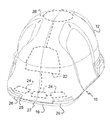
- FIG. 2 a bottom view of the smart hardhat of FIG. 1 ;
- FIG. 3 an exploded perspective view of a portable calibration station adapted to be secured to the hardhat;
- FIG. 4 a perspective view of a fixed calibration station adapted to receive a hardhat thereon;
- FIG. 5 is a flow chart showing one method of the invention.
- FIG. 6 is a flow chart showing another method of the invention for calibrating a plurality of remote smart devices using another smart devices as reference point.
- a smart device is generally shown at 10 . While the smart device 10 is shown to be a hard hat, it should be appreciated by those skilled in the art that the smart device 10 may be any device that has a level of connectivity and computational capability.
- the hard hat 10 has a hard outer shell 12 designed to cover and protect a head of the person wearing the hard hat 10 .
- the hard hat 10 defines an opening 14 (best seen in FIG. 2 ) to receive the head therein.
- a brim 16 extends out and away from the outer shell 12 over the portion of the hard hat 10 designed to be over the face of the person wearing it.
- an adjustable suspension band 18 extends around the interior 20 of the hard hat 10 to assist in fitting the hard hat 10 to the head securely and comfortably.
- the adjustable suspension band 18 also absorb energy from impacts and collisions.
- the hard hat 10 includes a control unit 22 .
- the control unit 22 is secured to the outer shell 12 and includes electronics to receive and transmit signals and memory to store signals and/or data received by sensors 24 . While three sensors 24 are show at or near the brim 16 , it should be appreciated by those skilled in the art that there may be fewer or more sensors 24 at the brim 16 . Additionally, there may be other sensors (not shown) located at locations other than at the brim 16 .
- the brim includes a light 25 and a camera 27 .
- the light 25 may illuminate the path in front of the user or it may be used to assist the camera 27 in recording information.
- a communication light or wave guide 29 is directed inwardly to illuminate in the peripheral vision of the user to indicate information to the user.
- the communication light 29 may emit light from different wavelengths (colors) or it may intermittently illuminate to send signals to the user.
- the sensors 24 , the light 25 , the camera 27 , and the communication light 29 are electrically connected to the control unit 22 .
- the communications unit 28 includes one or more antennae that transmit and receive signals to and from locations remote of the hard hat 10 .
- One or more electronic communication protocols may be employed by the communications unit 28 depending on the needs of the person wearing the hard hat 10 and the functionality incorporated into the overall electronics of the hard hat 10 .
- ports 30 for audible signals are positioned on the sides of the hard hat 10 at the opening 14 .
- Small speakers (not shown) are housed within the outer shell 12 and produce sound waves that are emitted out the audio ports 30 .
- Connection assemblies 32 are disposed adjacent the audio ports 30 and allow peripheral devices (none shown) to be secured to the hard hat 10 .
- the connection assemblies 32 are described in greater detail in U.S. patent application Ser. No. 15/087,972, the disclosure of which is expressly incorporated herein by reference.
- the invention is a calibration assembly 36 that calibrates the sensors 24 .
- the calibration assembly 36 is shown as a mobile assembly in FIG. 3 .
- the calibration assembly 36 includes an enclosing structure 38 and a calibrator 40 .
- the enclosing structure 38 is a plate that has an opening 42 designed to receive a calibration tube 44 thereon.
- the enclosing structure 38 is fitted to an underside 46 of the brim 16 and secured to the hard hat 10 during the calibration of the sensors 24 . When secured to the underside 46 of the brim 16 , the enclosing structure 38 and the underside 46 define a calibration space 47 .
- the calibrator 40 receives an element (in this example, a gas) through a gas supply tube 48 , which receives a gas from a canister 50 .
- the gas used as a control in the calibration of the sensors 24 could include carbon monoxide, hydrogen-sulfide, methane, nitrous oxide, carbon dioxide, smoke, and the like.
- the sensor 24 being tested may measure a non-gas element, such as light.
- the canister 50 would be replaced with a light source and the gas supply 48 and calibration 44 tubes would be replaced with wave guides or fiber optics.
- This alternative description is not intended to be limiting as there may be other elements that will be measurable using the calibration assembly 36 .
- FIG. 4 wherein like primed reference numerals represent similar elements as those shown in FIG. 3 , a tabletop version of the calibration assembly 36 ′ is shown.
- the tabletop version of the calibration assembly 38 ′ includes a station 52 .
- the canister 50 ′ is secured within the station 52 .
- the calibrator 40 ′ is also housed within the station 52 .
- the station 52 includes may include one or more enclosure structures 38 ′.
- Each of the enclosure structures 38 ′ includes a bay 54 for receiving a hard hat 10 therein.
- the bay 54 may be designed to calibrate sensors 24 regardless of whether the sensors 24 are located on the underside 46 of the brim 16 or somewhere else in the interior of the outer shell 12 . In case the sensors 24 being calibrated are located on the underside 46 of the brim 16 , a shelf 56 helps limit the calibration space adjacent the sensors 24 .
- one embodiment of the inventive method of calibrating a sensor 24 secured to a hard hat 10 is generally shown at 60 .
- the method 60 calibrates a sensor 24 for a defined parameter using a calibration assembly 36 adapted to receive the sensor 24 while it is secured to the hard hat 10 .
- the method begins at 62 .
- the method mechanically and wirelessly connects the hard hat 10 with a sensor 24 to the calibration assembly 36 , 36 ′ at 64 .
- a calibration space 47 , 47 ′ is created.
- the calibration space 47 , 47 ′ surrounds the sensor 24 to control the environment of which the sensor 24 will be sensing.
- a quantity of an element to be used for calibration is presented into the calibration space 47 , 47 ′. As stated above, this could be done by injecting a gas into the calibration space 47 , 47 ′ or it could be done differently should a non-gaseous element sensor be deemed necessary to calibrate. It will not matter what the sensor 24 is being calibrated as long as the calibration space 47 , 47 ′ is created to control the element being introduced into the space adjacent the sensor 24 .
- the hard hat 10 is wirelessly connected to the calibration assembly 36 , 36 ′ during the connection step 66 .
- the measured signal from a hard hat 10 is transmitted to the calibration assembly 36 , 36 ′ to compare and calibrate the settings for sensors 24 on the hard hat 10 .
- the method is terminated at 68 . If it is mechanically connected, a quantity of the element is introduced into the calibration space 47 , 47 ′ to expose the sensors 24 to a reference amount or quantity of the element at 70 .
- the quantity of the element introduced into the calibration space 47 , 47 ′ is then measured at 72 .
- a measured signal is created based on the quantity measured at 74 .
- the measured signal is then transmitted to the calibration assembly 36 , 36 ′ at 76 . Once received, the measured signal is compared against a predetermined level at 78 . If at 80 , the measured signal differs from the predetermined level by a threshold amount, the predetermined level of the sensor 24 is calibrated at 82 .
- the loop back after step 82 is done iteratively to create multiple data points for the calibration process. If the measured signal does not differ from the predetermined level by the threshold amount, the sensor 24 does not need to be calibrated and the method terminates at 84 .
- the calibration assembly 36 , 36 ′ will be able to read specific user parameters stored within the control unit 22 of the hard hat 10 in case one user has a heightened sensitivity to a particular element and the threshold level must be adjusted for that particular user.
- signals from other hard hats 10 may be incorporated into the calibration method.
- This method begins at 92 .
- a calibrated hard hat 10 is sent into the field at 93 . While in the field, the calibrated hard hat 10 is moved into close proximity of an uncalibrated hard hat 10 at 94 .
- a measurement is taken from the calibrated hard hat 10 at 96 and a measurement is taken from the uncalibrated hard hat 10 at 98 .
- the two readings are then compared at 100 .
- the compared value is then measured against a predetermined threshold at 102 . If the comparison value is greater than the predetermined value, the uncalibrated hard hat 10 is calibrated right there in the field at 104 .
- the uncalibrated hard hat 10 does not have to be returned to the calibration station 36 , 36 ′ and can be calibrated either in the field or it can be returned to the calibration stations 36 , 36 ′ for calibration.
- the status of the uncalibrated hard hat 10 is changed to calibrated at 105 so that it is not iteratively checked while it is deployed in the field. This status change may be timed out so that eventually it will be rechecked or sent back to a calibration station 36 , 36 ′ for a thorough or complete calibration independent of a calibrated hard hat 10 .
- the method then terminates at 106 .
- the method of FIG. 6 introduces the statistical/machine learning aspects into the calibration process, which allows the solution provided by FIG. 6 to adjust to real life variations in a dynamic manner.
Landscapes
- Engineering & Computer Science (AREA)
- Computer Networks & Wireless Communication (AREA)
- Signal Processing (AREA)
- Arrangements For Transmission Of Measured Signals (AREA)
Abstract
Description
Claims (7)
Priority Applications (1)
| Application Number | Priority Date | Filing Date | Title |
|---|---|---|---|
| US15/097,833 US9686136B1 (en) | 2016-04-13 | 2016-04-13 | Assembly and method for calibrating a sensor on a wearable device |
Applications Claiming Priority (1)
| Application Number | Priority Date | Filing Date | Title |
|---|---|---|---|
| US15/097,833 US9686136B1 (en) | 2016-04-13 | 2016-04-13 | Assembly and method for calibrating a sensor on a wearable device |
Publications (1)
| Publication Number | Publication Date |
|---|---|
| US9686136B1 true US9686136B1 (en) | 2017-06-20 |
Family
ID=59034137
Family Applications (1)
| Application Number | Title | Priority Date | Filing Date |
|---|---|---|---|
| US15/097,833 Active US9686136B1 (en) | 2016-04-13 | 2016-04-13 | Assembly and method for calibrating a sensor on a wearable device |
Country Status (1)
| Country | Link |
|---|---|
| US (1) | US9686136B1 (en) |
Cited By (10)
| Publication number | Priority date | Publication date | Assignee | Title |
|---|---|---|---|---|
| EP3547650A1 (en) * | 2018-03-28 | 2019-10-02 | INTEL Corporation | Methods and apparatus to dynamically control devices based on distributed data |
| US11116270B2 (en) * | 2014-10-17 | 2021-09-14 | Guardhat, Inc. | Electrical connection for suspension band attachment slot of a hard hat |
| US11462301B2 (en) | 2016-06-07 | 2022-10-04 | BlyncSync Technologies, LLC | System and method for fleet driver biometric tracking |
| US11559099B2 (en) | 2018-05-30 | 2023-01-24 | Schuberth Gmbh | Protective helmet |
| US11696610B2 (en) | 2017-12-15 | 2023-07-11 | Schuberth Gmbh | Protective helmet |
| WO2023141180A1 (en) * | 2022-01-19 | 2023-07-27 | VR Simulations, Inc. | Method for calibrating an extended reality headset for use with exercise equipment |
| US11944148B2 (en) | 2018-02-19 | 2024-04-02 | Schuberth Gmbh | Protective helmet |
| US12022906B2 (en) | 2016-08-26 | 2024-07-02 | Schuberth Gmbh | Protective helmet with an antenna |
| US12059047B2 (en) * | 2016-08-26 | 2024-08-13 | Schuberth Gmbh | Protective helmet |
| US12290129B2 (en) | 2016-11-28 | 2025-05-06 | Schuberth Gmbh | Outer shell for a safety helmet |
Citations (3)
| Publication number | Priority date | Publication date | Assignee | Title |
|---|---|---|---|---|
| US20130117707A1 (en) * | 2011-11-08 | 2013-05-09 | Google Inc. | Velocity-Based Triggering |
| US20130303946A1 (en) * | 2012-05-09 | 2013-11-14 | Western New England University | Wearable article for detecting an impact and method of operation |
| US20160173749A1 (en) * | 2013-07-18 | 2016-06-16 | Omg Plc | Still image capture with exposure control |
-
2016
- 2016-04-13 US US15/097,833 patent/US9686136B1/en active Active
Patent Citations (3)
| Publication number | Priority date | Publication date | Assignee | Title |
|---|---|---|---|---|
| US20130117707A1 (en) * | 2011-11-08 | 2013-05-09 | Google Inc. | Velocity-Based Triggering |
| US20130303946A1 (en) * | 2012-05-09 | 2013-11-14 | Western New England University | Wearable article for detecting an impact and method of operation |
| US20160173749A1 (en) * | 2013-07-18 | 2016-06-16 | Omg Plc | Still image capture with exposure control |
Cited By (14)
| Publication number | Priority date | Publication date | Assignee | Title |
|---|---|---|---|---|
| US11116270B2 (en) * | 2014-10-17 | 2021-09-14 | Guardhat, Inc. | Electrical connection for suspension band attachment slot of a hard hat |
| US11462301B2 (en) | 2016-06-07 | 2022-10-04 | BlyncSync Technologies, LLC | System and method for fleet driver biometric tracking |
| US12230366B2 (en) | 2016-06-07 | 2025-02-18 | BlyncSync Technologies, LLC | System and method for fleet driver biometric tracking |
| US12059047B2 (en) * | 2016-08-26 | 2024-08-13 | Schuberth Gmbh | Protective helmet |
| US12022906B2 (en) | 2016-08-26 | 2024-07-02 | Schuberth Gmbh | Protective helmet with an antenna |
| US12290129B2 (en) | 2016-11-28 | 2025-05-06 | Schuberth Gmbh | Outer shell for a safety helmet |
| US11696610B2 (en) | 2017-12-15 | 2023-07-11 | Schuberth Gmbh | Protective helmet |
| US11944148B2 (en) | 2018-02-19 | 2024-04-02 | Schuberth Gmbh | Protective helmet |
| EP3547650A1 (en) * | 2018-03-28 | 2019-10-02 | INTEL Corporation | Methods and apparatus to dynamically control devices based on distributed data |
| US11356315B2 (en) | 2018-03-28 | 2022-06-07 | Intel Corporation | Methods and apparatus to dynamically control devices based on distributed data |
| US12267389B2 (en) | 2018-03-28 | 2025-04-01 | Intel Corporation | Methods and apparatus to dynamically control devices based on distributed data |
| US11559099B2 (en) | 2018-05-30 | 2023-01-24 | Schuberth Gmbh | Protective helmet |
| WO2023141180A1 (en) * | 2022-01-19 | 2023-07-27 | VR Simulations, Inc. | Method for calibrating an extended reality headset for use with exercise equipment |
| US12453915B2 (en) | 2022-01-19 | 2025-10-28 | VR Simulations, Inc. | Method for calibrating an extended reality headset for use with exercise equipment |
Similar Documents
| Publication | Publication Date | Title |
|---|---|---|
| US9686136B1 (en) | Assembly and method for calibrating a sensor on a wearable device | |
| US10194233B2 (en) | Earphones and earbuds with physiologic sensors | |
| EP3821615A1 (en) | Identification of cushioning members in personal audio devices | |
| US9064386B2 (en) | Alarm enhancing protective cover for safety instruments with optional calibration chamber | |
| WO2011138190A1 (en) | System for simulating electromagnetic environments comprising an array including a plurality of probes | |
| US20170089795A1 (en) | Waterproof barometric sensor in an electronic device | |
| US20180214041A1 (en) | Biological information measurement apparatus | |
| US20160199001A1 (en) | Heart rate detection earphone | |
| US20230292071A1 (en) | Portable calibration system for audio equipment and devices | |
| KR960706067A (en) | IMPROVED TYMPANIC THERMOMETER | |
| US20140216137A1 (en) | Gas sensor with thermal measurement compensation | |
| EP1123042B1 (en) | Sensing ear temperature, acoustic reflectance and chemical components in the ear | |
| US20220287639A1 (en) | Hearing device with optical sensor for determining a tissue property | |
| US7466631B1 (en) | Enhanced sensitivity pressure tolerant fiber optic hydrophone | |
| KR20080076515A (en) | Non-dispersive Infrared Gas Sensor with Fully Oval Reflector | |
| US7305327B2 (en) | Wireless meter for real time measurements and method therefor | |
| US20210022614A1 (en) | Measurement apparatus, measurement instrument, measurement system, server, analysis method, storage medium, and data structure | |
| US5919143A (en) | Apparatus and method for analysis of acoustic reflectance and thermal radiation of an ear | |
| US20170059438A1 (en) | Physical quantity measuring device | |
| JP2021071402A (en) | Pressure meter | |
| US11079318B2 (en) | Gas sensing device and a method for sensing gas | |
| KR20180108359A (en) | Body temperature measurement device | |
| JP3413918B2 (en) | Radiation thermometer | |
| JP7388266B2 (en) | ear thermometer | |
| US11871894B2 (en) | Biological information management system |
Legal Events
| Date | Code | Title | Description |
|---|---|---|---|
| AS | Assignment |
Owner name: GUARDHAT, INC., MICHIGAN Free format text: ASSIGNMENT OF ASSIGNORS INTEREST;ASSIGNORS:DEY, SAIKAT;REEPMEYER, GERRIT;SENGUPTA, ANUPAM;AND OTHERS;REEL/FRAME:038587/0431 Effective date: 20160429 |
|
| STCF | Information on status: patent grant |
Free format text: PATENTED CASE |
|
| MAFP | Maintenance fee payment |
Free format text: PAYMENT OF MAINTENANCE FEE, 4TH YR, SMALL ENTITY (ORIGINAL EVENT CODE: M2551); ENTITY STATUS OF PATENT OWNER: SMALL ENTITY Year of fee payment: 4 |
|
| AS | Assignment |
Owner name: SILICON VALLEY BANK, MASSACHUSETTS Free format text: SECURITY INTEREST;ASSIGNOR:GUARDHAT, INC.;REEL/FRAME:062505/0917 Effective date: 20230124 |
|
| FEPP | Fee payment procedure |
Free format text: 7.5 YR SURCHARGE - LATE PMT W/IN 6 MO, SMALL ENTITY (ORIGINAL EVENT CODE: M2555); ENTITY STATUS OF PATENT OWNER: SMALL ENTITY |
|
| MAFP | Maintenance fee payment |
Free format text: PAYMENT OF MAINTENANCE FEE, 8TH YR, SMALL ENTITY (ORIGINAL EVENT CODE: M2552); ENTITY STATUS OF PATENT OWNER: SMALL ENTITY Year of fee payment: 8 |