US9686096B2 - Acoustic manipulation of particles in standing wave fields - Google Patents
Acoustic manipulation of particles in standing wave fields Download PDFInfo
- Publication number
- US9686096B2 US9686096B2 US15/414,465 US201715414465A US9686096B2 US 9686096 B2 US9686096 B2 US 9686096B2 US 201715414465 A US201715414465 A US 201715414465A US 9686096 B2 US9686096 B2 US 9686096B2
- Authority
- US
- United States
- Prior art keywords
- acoustic
- standing wave
- fluid
- modes
- ultrasonic transducer
- Prior art date
- Legal status (The legal status is an assumption and is not a legal conclusion. Google has not performed a legal analysis and makes no representation as to the accuracy of the status listed.)
- Active
Links
Images


Classifications
-
- H—ELECTRICITY
- H04—ELECTRIC COMMUNICATION TECHNIQUE
- H04L—TRANSMISSION OF DIGITAL INFORMATION, e.g. TELEGRAPHIC COMMUNICATION
- H04L12/00—Data switching networks
- H04L12/28—Data switching networks characterised by path configuration, e.g. LAN [Local Area Networks] or WAN [Wide Area Networks]
- H04L12/40—Bus networks
- H04L12/40006—Architecture of a communication node
- H04L12/40032—Details regarding a bus interface enhancer
-
- B—PERFORMING OPERATIONS; TRANSPORTING
- B01—PHYSICAL OR CHEMICAL PROCESSES OR APPARATUS IN GENERAL
- B01D—SEPARATION
- B01D17/00—Separation of liquids, not provided for elsewhere, e.g. by thermal diffusion
- B01D17/02—Separation of non-miscible liquids
- B01D17/0202—Separation of non-miscible liquids by ab- or adsorption
-
- B—PERFORMING OPERATIONS; TRANSPORTING
- B01—PHYSICAL OR CHEMICAL PROCESSES OR APPARATUS IN GENERAL
- B01D—SEPARATION
- B01D17/00—Separation of liquids, not provided for elsewhere, e.g. by thermal diffusion
-
- B—PERFORMING OPERATIONS; TRANSPORTING
- B01—PHYSICAL OR CHEMICAL PROCESSES OR APPARATUS IN GENERAL
- B01D—SEPARATION
- B01D21/00—Separation of suspended solid particles from liquids by sedimentation
- B01D21/0084—Enhancing liquid-particle separation using the flotation principle
-
- B—PERFORMING OPERATIONS; TRANSPORTING
- B01—PHYSICAL OR CHEMICAL PROCESSES OR APPARATUS IN GENERAL
- B01D—SEPARATION
- B01D21/00—Separation of suspended solid particles from liquids by sedimentation
- B01D21/28—Mechanical auxiliary equipment for acceleration of sedimentation, e.g. by vibrators or the like
- B01D21/283—Settling tanks provided with vibrators
-
- B—PERFORMING OPERATIONS; TRANSPORTING
- B06—GENERATING OR TRANSMITTING MECHANICAL VIBRATIONS IN GENERAL
- B06B—METHODS OR APPARATUS FOR GENERATING OR TRANSMITTING MECHANICAL VIBRATIONS OF INFRASONIC, SONIC, OR ULTRASONIC FREQUENCY, e.g. FOR PERFORMING MECHANICAL WORK IN GENERAL
- B06B1/00—Methods or apparatus for generating mechanical vibrations of infrasonic, sonic, or ultrasonic frequency
- B06B1/02—Methods or apparatus for generating mechanical vibrations of infrasonic, sonic, or ultrasonic frequency making use of electrical energy
- B06B1/0207—Driving circuits
- B06B1/0223—Driving circuits for generating signals continuous in time
- B06B1/0269—Driving circuits for generating signals continuous in time for generating multiple frequencies
- B06B1/0276—Driving circuits for generating signals continuous in time for generating multiple frequencies with simultaneous generation, e.g. with modulation, harmonics
-
- B—PERFORMING OPERATIONS; TRANSPORTING
- B06—GENERATING OR TRANSMITTING MECHANICAL VIBRATIONS IN GENERAL
- B06B—METHODS OR APPARATUS FOR GENERATING OR TRANSMITTING MECHANICAL VIBRATIONS OF INFRASONIC, SONIC, OR ULTRASONIC FREQUENCY, e.g. FOR PERFORMING MECHANICAL WORK IN GENERAL
- B06B1/00—Methods or apparatus for generating mechanical vibrations of infrasonic, sonic, or ultrasonic frequency
- B06B1/02—Methods or apparatus for generating mechanical vibrations of infrasonic, sonic, or ultrasonic frequency making use of electrical energy
- B06B1/06—Methods or apparatus for generating mechanical vibrations of infrasonic, sonic, or ultrasonic frequency making use of electrical energy operating with piezoelectric effect or with electrostriction
- B06B1/0644—Methods or apparatus for generating mechanical vibrations of infrasonic, sonic, or ultrasonic frequency making use of electrical energy operating with piezoelectric effect or with electrostriction using a single piezoelectric element
- B06B1/0662—Methods or apparatus for generating mechanical vibrations of infrasonic, sonic, or ultrasonic frequency making use of electrical energy operating with piezoelectric effect or with electrostriction using a single piezoelectric element with an electrode on the sensitive surface
- B06B1/0674—Methods or apparatus for generating mechanical vibrations of infrasonic, sonic, or ultrasonic frequency making use of electrical energy operating with piezoelectric effect or with electrostriction using a single piezoelectric element with an electrode on the sensitive surface and a low impedance backing, e.g. air
-
- C—CHEMISTRY; METALLURGY
- C12—BIOCHEMISTRY; BEER; SPIRITS; WINE; VINEGAR; MICROBIOLOGY; ENZYMOLOGY; MUTATION OR GENETIC ENGINEERING
- C12M—APPARATUS FOR ENZYMOLOGY OR MICROBIOLOGY; APPARATUS FOR CULTURING MICROORGANISMS FOR PRODUCING BIOMASS, FOR GROWING CELLS OR FOR OBTAINING FERMENTATION OR METABOLIC PRODUCTS, i.e. BIOREACTORS OR FERMENTERS
- C12M47/00—Means for after-treatment of the produced biomass or of the fermentation or metabolic products, e.g. storage of biomass
- C12M47/02—Separating microorganisms from the culture medium; Concentration of biomass
-
- B—PERFORMING OPERATIONS; TRANSPORTING
- B01—PHYSICAL OR CHEMICAL PROCESSES OR APPARATUS IN GENERAL
- B01D—SEPARATION
- B01D43/00—Separating particles from liquids, or liquids from solids, otherwise than by sedimentation or filtration
-
- C—CHEMISTRY; METALLURGY
- C02—TREATMENT OF WATER, WASTE WATER, SEWAGE, OR SLUDGE
- C02F—TREATMENT OF WATER, WASTE WATER, SEWAGE, OR SLUDGE
- C02F1/00—Treatment of water, waste water, or sewage
- C02F1/30—Treatment of water, waste water, or sewage by irradiation
- C02F1/32—Treatment of water, waste water, or sewage by irradiation with ultraviolet light
-
- H—ELECTRICITY
- H04—ELECTRIC COMMUNICATION TECHNIQUE
- H04L—TRANSMISSION OF DIGITAL INFORMATION, e.g. TELEGRAPHIC COMMUNICATION
- H04L12/00—Data switching networks
- H04L12/28—Data switching networks characterised by path configuration, e.g. LAN [Local Area Networks] or WAN [Wide Area Networks]
- H04L12/40—Bus networks
- H04L2012/4026—Bus for use in automation systems
Definitions
- the subject matter described herein relates to the use of ultrasonically generated acoustic standing waves to achieve trapping, concentration, and separation of suspended-phase components and thereby remove such contaminants from a fluid medium such as water.
- aggregation of the particles to form larger clumps is typically due to some attraction or adhesion between the particles or the addition of a flocculating agent that aids in attracting and aggregating the particles. Attractive forces between the particles may be ionic or physical entanglement.
- a physical filtration process is utilized to separate the aggregated, agglomerated, flocculated or otherwise process-formed particle clumps.
- Most of the work reported in the literature for particle removal from water involves replaceable filter units consisting generally of packed cartridges, filter membranes, or special filter papers. If the separation process is a filter separation process, the physical filter media and the clumps of particles that have been separated from the fluid media are typically discarded, thus creating additional waste and increasing costs. Also, with the use of this physical filtration process, the yield of the filtrate is lessened, as some of it is used to saturate the filtering material.
- continuous filtration may be carried out.
- Such continuous methods would be useful in various filtration applications, such as the filtering of oil from water, components from blood, tailings from water in tailing ponds, and, generally, particles from a fluid stream and immiscible or emulsified fluids from a fluid stream.
- Acoustophoresis is the separation of particles and secondary fluids from a primary or host fluid using high intensity acoustic standing waves, and without the use of membranes or physical size exclusion filters. It has been known that high intensity standing waves of sound can exert forces on particles in a fluid when there is a differential in both density and/or compressibility, otherwise known as the acoustic contrast factor.
- the pressure profile in a standing wave contains areas of local minimum pressure amplitudes at its nodes and local maxima at its anti-nodes. Depending on the density and compressibility of the particles, they will be trapped at the nodes or anti-nodes of the standing wave. Generally, the higher the frequency of the standing wave, the smaller the particles that can be trapped due the pressure of the standing wave.
- planar acoustic standing waves with resonance frequencies of n*c/2 L, where n is an integer, c is the speed of sound of the fluid, and L is the length of the acoustic resonator resonator or the length of the standing wave, have been used to accomplish the separation process.
- a single planar wave tends to trap the particles or secondary fluid in a manner such that they can only be separated from the primary fluid by turning off the planar standing wave. This does not allow for continuous operation.
- the amount of power that is needed to generate the acoustic planar standing wave tends to heat the primary fluid through waste energy.
- acoustophoresis devices have thus had limited efficacy due to several factors including heat generation, use of planar standing waves, limits on fluid flow, and the inability to capture different types of materials. It would therefore be desirable to provide systems and methods of generating optimized particle clusters to improve gravity separation and collection efficiency. Improved acoustophoresis devices using improved fluid dynamics would also be desirable, so the acoustophoresis can be a continuous process.
- the present disclosure relates, in various embodiments, to acoustophoretic devices and methods of separating a second fluid or a particulate from a host fluid.
- a superposition of multi-dimensional acoustic standing waves is used to continuously trap the second fluid or particulate, which then agglomerates, aggregates, clumps, or coalesces together, and subsequently rises or settles out of the host fluid due to buoyancy or gravity forces, and exits the acoustic chamber.
- the acoustophoretic device comprises an acoustic chamber having at least one inlet and at least one outlet; at least one ultrasonic transducer located on a wall of the acoustic chamber, the at least one ultrasonic transducer including a piezoelectric material driven by a voltage signal to create a superposition of multi-dimensional acoustic standing waves in the acoustic chamber; and a reflector located on a wall on the opposite side of the acoustic chamber from the at least one ultrasonic transducer.
- the method further comprises sending a voltage signal to drive the at least one ultrasonic transducer in a displacement profile that is a superposition of a combination of different modes (such as planar, fundamental, and/or higher order mode shapes) that are the same order of magnitude to create the multi-dimensional acoustic standing wave in the acoustic chamber such that the second fluid or particulate is continuously trapped in the standing wave, and then agglomerates, aggregates, clumps, or coalesces together, and subsequently rises or settles out of the host fluid due to buoyancy or gravity forces, and exits the acoustic chamber.
- modes such as planar, fundamental, and/or higher order mode shapes
- Mode (1, 1) is known as the fundamental mode.
- the fundamental and higher order mode shapes may have peaks within 0.005 megahertz (MHz) of each other.
- the higher order mode shapes may include modes (1, 3); (1, 5); (3, 3); (3, 5); and (5, 5).
- the higher order modes may include modes up to (25, 25) and higher.
- the different modes may have peaks within a frequency interval between resonance frequencies of planar standing waves.
- a frequency of excitation of the piezoelectric material can be changed or dithered over a small interval, exciting the piezoelectric material in multiple higher order modes, and then cycling the frequency back through lower modes of the piezoelectric material, thereby allowing for various multi-dimensional wave shapes, along with a single piston mode shape, to be generated over a designated time.
- a frequency of excitation of the piezoelectric material is a fixed frequency excitation where a weighted combination of several modes contribute to the overall displacement profile of the piezoelectric element.
- the piezoelectric material may be configured to vibrate to create an acoustic pressure profile in the acoustic chamber in a direction that is orthogonal to a direction of propagation of the acoustic standing wave, the pressure profile including multiple maxima and minima.
- the multi-dimensional standing wave results in an acoustic radiation force having an axial force component and a lateral force component that are the same order of magnitude.
- the multi-dimensional acoustic standing wave can be generated in the acoustic chamber normal to a direction of flow therethrough.
- the piezoelectric material can vibrate to create a pressure profile across the surface of the flowing mixture, the pressure profile having multiple maxima and minima. Hot spots in the mixture can be generated that are located at a minimum of the acoustic radiation potential.
- the voltage signal can have a sinusoidal, square, sawtooth, triangle, or pulsed waveform.
- the voltage signal can have a frequency of 100 kHz to 10 MHz.
- the voltage signal can be driven with amplitude or frequency modulation start/stop capability to eliminate acoustic streaming.
- the reflector may have a non-planar surface.
- a multi-dimensional acoustic standing wave is generated between two or more acoustic transducers arranged to direct a generated acoustic wave toward each other.
- the reflector may be replaced by an acoustic transducer that is capable of generating a multi-dimensional standing wave.
- the combination of transducers contributes to generating and reflecting acoustic waves to create a multi-dimensional standing wave.
- the acoustic waves generated by the transducers can arranged to constructively and/or destructively interfere with each other to form a multi-dimensional standing wave.
- an acoustic transducer pair, or acoustic transducer/reflector pair are configured to operate in multi-mode.
- Multi-mode operation provides for a number of modes being present at a certain operating point, such as a frequency operating point, for example.
- Multi-mode operation may occur at operating points between instances of single-mode operation.
- a primarily dominant mode may be present, in addition to one or more secondary modes.
- the superposition of modes may contribute to forming a multi-dimensional acoustic standing wave, with lateral as well as axial acoustic radiation forces.
- the primary and secondary modes may vary depending on selected operating points, for example.
- an acoustic transducer When an acoustic transducer generates an acoustic wave that is reflected back to the transducer to create a standing wave, the reflected wave can act as a load on the acoustic transducer.
- the loading of the transducer from a reflected wave or other sources of loading, such as a second acoustic transducer acoustically coupled through a fluid, can influence multi-mode operation. For example, a transducer load may change the frequency at which a given mode becomes dominant or peaks. A desired operating point for multi-mode operation, and the characteristics of the different modes, may thus be impacted by loading.
- the at least one ultrasonic transducer may comprise: a housing having a top end, a bottom end, and an interior volume; and a piezoelectric element at the bottom end of the housing having an exposed exterior surface and an interior surface, the piezoelectric element being able to vibrate when driven by a voltage signal.
- a backing layer can contact the interior surface of the piezoelectric element, the backing layer being made of a substantially acoustically transparent material.
- the substantially acoustically transparent material may be balsa wood, cork, or foam.
- the substantially acoustically transparent material may have a thickness of up to 1 inch.
- the substantially acoustically transparent material may be in the form of a lattice.
- An exterior surface of the piezoelectric element can be covered by a wear surface material with a thickness of a half wavelength or less, the wear surface material being a urethane, epoxy, or silicone coating.
- the piezoelectric element has no backing layer or wear layer.
- the piezoelectric element can be a crystalline, semi-crystalline, or non-crystalline.
- the mixture of the second fluid or particulate can flow vertically downwards, and the second fluid or particulate can float upward to a collection duct.
- the mixture can flow vertically upwards, and the second fluid or particulate can sink down to a collection duct.
- the particulate may be Chinese hamster ovary (CHO) cells, NS0 hybridoma cells, baby hamster kidney (BHK) cells, or human cells.
- the acoustic standing wave may be a multi-dimensional acoustic standing wave. Examples of such multi-dimensional acoustic standing waves can be found in commonly owned U.S. Pat. No. 9,228,183, the entire contents of which are hereby fully incorporated by reference.
- the acoustic standing wave can be a planar acoustic standing wave.
- the acoustic standing wave may be a combination of a planar acoustic standing wave and a multidimensional acoustic standing wave, where the planar acoustic standing wave and multidimensional acoustic standing wave are super-positioned on each other.
- Also disclosed herein are devices for separating a second fluid or a particulate from a host fluid comprising: an acoustic chamber including at least one inlet and at least one outlet; at least one ultrasonic transducer coupled to the acoustic chamber to permit generation of an acoustic wave therein, the at least one ultrasonic transducer including a piezoelectric material configured to be driven so that the piezoelectric material vibrates in higher order modes of the general formula (m, n), wherein m and n are independently 1 or greater (or 3 or greater), to create a multi-dimensional acoustic standing wave in the acoustic chamber; and a reflector located opposite to the at least one ultrasonic transducer.
- the higher order modes may be of the same order of magnitude.
- the higher order modes can include at least two modes selected from the group consisting of modes (3, 3); (3, 5); and (5, 5).
- Also described herein are devices for separating a second fluid or a particulate from a host fluid comprising: an acoustic chamber including at least one inlet and at least one outlet; at least one ultrasonic transducer coupled to the acoustic chamber to permit generation of an acoustic wave therein, the at least one ultrasonic transducer including a piezoelectric material configured to be driven in a displacement profile that is a superposition of a combination of different modes to create a multi-dimensional acoustic standing wave in the acoustic chamber; where the multidimensional acoustic standing wave is the result of the perturbation of a PZT material having characteristics of a 33 orientation where the piezoelectric elements are characterized by independent ⁇ values, independent e values, and independent ⁇ values such that, in a resonant cavity with an acoustic standing wave, the electrical boundary conditions are defined by the following equations:
- V is the voltage amplitude
- n is the periodic index
- m is the periodic index for the (n,m) mode of interest
- a reflector located across the acoustic chamber from the at least one ultrasonic transducer.
- FIG. 1 is a graph showing the relationship of the acoustic radiation force, gravity/buoyancy force, and Stokes' drag force to particle size.
- the horizontal axis is in microns ( ⁇ m) and the vertical axis is in Newtons (N).
- FIG. 2 illustrates a general configuration of a piezoelectric element separated from a reflective boundary layer by a water layer.
- FIG. 3 presents the traditional approach of utilizing a transducer and reflector to generate a planar standing wave to create loosely packed planes of particles in an acoustic chamber.
- Three views are seen: a reflector view, a system view, and an isometric view.
- FIG. 4 presents a new approach according to the present disclosure of utilizing a transducer and reflector to generate a multi-dimensional acoustic standing wave to create tightly packed cluster of particles in an acoustic chamber.
- Three views are seen: a reflector view, a system view, and an isometric view.
- FIG. 5 is a diagram illustrating an acoustophoretic separation method according to the present disclosure for a second fluid or particle less dense than a host fluid.
- FIG. 6 is a diagram illustrating an acoustophoretic separation method according to the present disclosure for a second fluid or particle denser than a host fluid.
- FIG. 7 is a cross-sectional diagram of a conventional ultrasonic transducer.
- FIG. 8 is a cross-sectional diagram of an ultrasonic transducer according to the present disclosure. An air gap is present within the transducer, and no backing layer or wear plate is present.
- FIG. 9 is a cross-sectional diagram of an ultrasonic transducer according to the present disclosure. An air gap is present within the transducer, and a backing layer and wear plate are present.
- FIG. 10 shows the In-Plane and Out-of-Plane displacement of a piezoelectric crystal where composite waves are present.
- FIG. 11 presents analytical results for the displacement response of a 25.4 ⁇ 25.4 ⁇ 1 mm PZT-8 piezoelectric crystal with a radiating water layer.
- FIG. 12 presents analytical results for the displacement response of a 25.4 ⁇ 25.4 ⁇ 1 mm PZT-8 piezoelectric crystal with a 25.4 mm fluid chamber terminated by an acoustic reflector.
- FIG. 13 presents a two-dimensional COMSOL numerical model of the piezoelectric equations according to the present disclosure.
- FIG. 14 presents numerical results for the displacement response of a 25.4 ⁇ 25.4 ⁇ 1 mm PZT-8 piezoelectric crystal with a 25.4 mm fluid chamber terminated by an acoustic reflector.
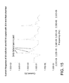
- FIG. 15 presents numerical results for the current response of a 25.4 ⁇ 25.4 ⁇ 1 mm PZT-8 piezoelectric crystal with a 25.4 mm fluid chamber terminated by an acoustic reflector.
- FIG. 16 presents experimental results for the current response of a 25.4 ⁇ 25.4 ⁇ 1 mm PZT-8 piezoelectric crystal operated with a 30 kHz frequency sweep with a 25.4 mm fluid chamber terminated by an acoustic reflector.
- the modifier “about” used in connection with a quantity is inclusive of the stated value and has the meaning dictated by the context. When used in the context of a range, the modifier “about” should also be considered as disclosing the range defined by the absolute values of the two endpoints. For example, the range of from about 2 to about 10′′ also discloses the range “from 2 to 10.”
- the term “about” may refer to plus or minus 10% of the indicated number. For example, “about 10%” may indicate a range of 9% to 11%, and “about 1” may mean from 0.9-1.1.
- the terms “upper” and “lower” are relative to each other in location, i.e. an upper component is located at a higher elevation than a lower component in a given orientation, but these terms can change if the device is flipped.
- the terms “inlet” and “outlet” are relative to a fluid flowing through them with respect to a given structure, e.g. a fluid flows through the inlet into the structure and flows through the outlet out of the structure.
- upstream and “downstream” are relative to the direction in which a fluid flows through various components, i.e. the flow fluids through an upstream component prior to flowing through the downstream component. It should be noted that in a loop, a first component can be described as being both upstream of and downstream of a second component.
- top and bottom are used to refer to surfaces where the top is always higher than the bottom/base relative to an absolute reference, i.e. the surface of the earth.
- upwards and downwards are also relative to an absolute reference; upwards is always against the gravity of the earth.
- Two numbers are of the same order of magnitude if the quotient of the larger number divided by the smaller number is a value of at least 1 and less than 10.
- Acoustophoresis is the separation of particles and secondary fluids from a primary or host fluid using high-intensity acoustic standing waves, and without the use of membranes or physical size exclusion filters. It has been known that high intensity standing waves of sound can exert forces on particles in a fluid when there is a differential in both density and/or compressibility, otherwise known as the acoustic contrast factor.
- the pressure profile in a standing wave contains areas of local minimum pressure amplitudes at its nodes and local maxima at its anti-nodes. Depending on the density and compressibility of the particles, they will be trapped at the nodes or anti-nodes of the standing wave. Generally, the higher the frequency of the standing wave, the smaller the particles that can be trapped due the pressure of the standing wave.
- the fast oscillations may generate a non-oscillating force on particles suspended in the liquid or on an interface between liquids.
- This force is known as the acoustic radiation force.
- the force originates from the non-linearity of the propagating wave.
- the wave is distorted as it propagates and the time-averages are nonzero.
- the first non-zero term will be the second-order term, which accounts for the acoustic radiation force.
- the acoustic radiation force on a particle, or a cell, in a fluid suspension is a function of the difference in radiation pressure on either side of the particle or cell.
- the physical description of the radiation force is a superposition of the incident wave and a scattered wave, in addition to the effect of the non-rigid particle oscillating with a different speed compared to the surrounding medium thereby radiating a wave.
- the following equation presents an analytical expression for the acoustic radiation force on a particle, or cell, in a fluid suspension in a planar standing wave.
- ⁇ ⁇ ( ⁇ , ⁇ ) 5 ⁇ ⁇ ⁇ - 2 ⁇ ⁇ m 2 ⁇ ⁇ ⁇ + ⁇ m - ⁇ ⁇ ⁇ m
- ⁇ p is the particle density
- ⁇ m is the fluid medium density
- ⁇ p is the compressibility of the particle
- ⁇ m is the compressibility of the fluid medium
- p the acoustic pressure
- u the fluid particle velocity
- ⁇ the ratio of cell density ⁇ p to fluid density ⁇ f
- ⁇ the ratio of cell sound speed c p to fluid sound speed c f
- V o the volume of the cell
- ⁇ > indicates time averaging over the period of the wave.
- Gork'ov's model is for a single particle in a standing wave and is limited to particle sizes that are small with respect to the wavelength of the sound fields in the fluid and the particle. It also does not take into account the effect of viscosity of the fluid and the particle on the radiation force. As a result, this model cannot be used for macro-scale ultrasonic separators since particle clusters can grow quite large.
- FIG. 1 is a log-log graph (logarithmic y-axis, logarithmic x-axis) that shows the scaling of the acoustic radiation force, fluid drag force, and buoyancy force with particle radius. Calculations are done for a typical mammalian cell used in experiments. In the experiment, the mammalian cell had a density ( ⁇ p ) of 1,050 kg/m 3 and a cell sound speed (c p ) of 1,550 m/s.
- the fluid in which the particle was flowed was water having a density ( ⁇ w ) of 1000 kg/m 3 , a fluid sound speed (c f ) of 1500 m/s, and a flow rate (v f ) of 4 cm/min.
- the experiment used 33 PZT-8 ultrasonic transducers driven at a frequency (f) of 2.2 MHz at a pressure (p) of 1 MPa.
- the gravity/buoyancy force is a particle volume dependent force, and is therefore negligible for particle sizes on the order of micron, but grows, and becomes significant for particle sizes on the order of hundreds of microns.
- the fluid drag force scales linearly with fluid velocity, and therefore typically exceeds the buoyancy force for micron sized particles, but is negligible for larger sized particles on the order of hundreds of microns.
- the acoustic radiation force scaling is different. When the particle size is small, Gor′kov's equation is accurate and the acoustic trapping force scales with the volume of the particle.
- the acoustic radiation force no longer increases with the cube of the particle radius, and will rapidly vanish at a certain critical particle size.
- the radiation force increases again in magnitude but with opposite phase (not shown in the graph). This pattern repeats for increasing particle sizes.
- FIG. 1 explains how small particles can be trapped continuously in a standing wave, grow into larger particles or clumps, and then eventually will rise or settle out because of increased buoyancy force.
- FIG. 2 shows a very general configuration of a piezoelectric material with electrodes on its faces. One electrode is configured as a periodic electric potential electrode, while the other electrode is configured as a ground electrode. The piezoelectric material is located opposite an acoustic reflector that provides a reflective boundary condition. The reflector and piezoelectric material are separated by a water layer.
- the general formulation of the piezoelectric equations is:
- V is the voltage amplitude
- n is the periodic index
- m is the periodic index for the (n,m) mode of interest.
- the acoustophoretic separation technology of the present disclosure employs multi-dimensional ultrasonic acoustic standing waves, planar acoustic standing waves or combinations, i.e., superpositions, of planar and multidimensional acoustic standing waves (collectively referred to herein simple as acoustic standing waves) to trap particles or a secondary fluid in a volume of fluid containing said particles/secondary fluid.
- FIG. 3 presents the traditional approach of utilizing a transducer and reflector located opposite one another to generate a planar standing wave therebetween.
- the left side of FIG. 3 presents a view of the acoustic chamber as seen through the reflector, while the middle picture of FIG. 3 presents a system view of the acoustic chamber from above.
- the generation of a planar standing wave in an acoustic chamber results in the creation of loosely packed planes of particles in the acoustic chamber, typically corresponding to the pressure nodal planes for particles with positive acoustic contrast.
- FIG. 4 presents a new approach of utilizing a transducer and reflector located opposite one another to generate a multi-dimensional acoustic standing wave therebetween, or a superposition of multi-dimensional acoustic standing waves.
- the left side of FIG. 4 presents a view of the acoustic chamber as seen through the reflector, while the middle picture of FIG. 4 presents a system view of the acoustic chamber from above.
- FIG. 4 presents a new approach of utilizing a transducer and reflector located opposite one another to generate a multi-dimensional acoustic standing wave therebetween, or a superposition of multi-dimensional acoustic standing waves.
- the left side of FIG. 4 presents a view of the acoustic chamber as seen through the reflector
- the middle picture of FIG. 4 presents a system view of the acoustic chamber from above.
- FIG. 4 presents a new approach of utilizing a transducer and reflector located opposite one another to generate a multi-dimensional a
- the generation of a multi-dimensional acoustic standing wave in an acoustic chamber results in the creation of tightly packed clusters of particles in the acoustic chamber, typically corresponding to the location of the pressure nodes or anti-nodes in the standing wave depending on acoustic contrast factor.
- the particles or secondary fluid collect at the nodes or anti-nodes of the acoustic standing wave, depending on the particles' or secondary fluid's acoustic contrast factor relative to the host fluid, forming clusters/clumps/agglomerates/coalesced droplets that continuously fall out of the acoustic standing wave when the clusters have grown to a size large enough to overcome the holding force of the acoustic standing wave (e.g. by coalescence or agglomeration) and the particle/secondary fluid density is higher than the host fluid, or to rise out of the acoustic standing wave when the particle/secondary fluid density is less than the host fluid.
- the acoustic radiation force is proportional to the particle volume (e.g.
- the cube of the radius when the particle is small relative to the wavelength. It is proportional to frequency and the acoustic contrast factor. It also scales with acoustic energy (e.g. the square of the acoustic pressure amplitude).
- acoustic energy e.g. the square of the acoustic pressure amplitude.
- the sinusoidal spatial variation of the force is what drives the particles to the stable axial positions within the standing waves.
- the acoustic radiation force exerted on the particles is stronger than the combined effect of fluid drag force and buoyancy and gravitational force, the particle is trapped within the acoustic standing wave field. This results in concentration, agglomeration and/or coalescence of the trapped particles.
- the strong lateral forces create rapid clustering of particles.
- Micron-sized particles e.g., bacteria, mammalian cells, micro-algae, metal particles, yeast, fungi, lipids, oil droplets, red blood cells, white blood cells, platelets, etc.
- a suspension with several different particle sizes it is possible by tuning of the system parameters to settle out the group of particles that are larger in size whereas the group of particles smaller in size can be kept in suspension. These two layers can then be harvested separately.
- a repeated process can then be used to fractionate groups of different sized particles according to size.
- the multi-dimensional acoustic standing waves generated by each transducer can be of different frequencies.
- acoustophoresis device is in the processing of bioreactor materials. It is important to be able to separate relatively larger cells and cell debris from the expressed materials that are in the host fluid.
- the expressed materials are composed of biomolecules such as recombinant proteins or monoclonal antibodies, and are the desired product to be recovered.
- acoustophoresis the separation of the cells and cell debris is very efficient and leads to very little loss of the expressed materials. This is an improvement over current filtration processes (depth filtration, tangential flow filtration, and the like), which show limited efficiencies at high cell densities, so that the loss of the expressed materials in the filter beds themselves can be up to 5% of the materials produced by the bioreactor.
- mammalian cell cultures including Chinese hamster ovary (CHO), NS0 hybridoma cells, baby hamster kidney (BHK) cells, insect cells, and human cells (e.g. T-cells, B-cells, stem cells, red blood cells), and living/biological cells in general has proven to be a very efficacious way of producing/expressing the recombinant proteins and monoclonal antibodies used with today's pharmaceuticals.
- the filtration of the mammalian cells and the mammalian cell debris through acoustophoresis aids in greatly increasing the yield of the bioreactor.
- the acoustophoresis process may also be coupled with a standard filtration process upstream or downstream, such as depth filtration, tangential flow filtration (TFF), or other physical filtration processes.
- the acoustic contrast factor is a function of the ratio of particle to fluid compressibility and particle to fluid density.
- Most cell types present a higher density and lower compressibility than the medium in which they are suspended, so that the acoustic contrast factor between the cells and the medium has a positive value.
- the axial acoustic radiation force (ARF) drives the cells, with a positive contrast factor, to the pressure nodal planes, whereas cells or other particles with a negative contrast factor are driven to the pressure anti-nodal planes.
- the radial or lateral component of the ARF is larger than the combined effect of fluid drag force and gravitational force.
- the radial or lateral component drives the cells/particles to specific locations (points) within these planes where they cluster, clump, agglomerate, or coalesce into larger groups, which will then continuously gravity separate from the fluid.
- the ultrasonic transducer(s) generate a three-dimensional or multi-dimensional acoustic standing wave in the fluid that exerts a lateral force on the suspended particles to accompany the axial force so as to increase the particle trapping and clumping capabilities of the standing wave.
- the technology disclosed in this application provides for a lateral force to be of the same order of magnitude as the axial force (i.e. a multi-dimensional acoustic standing wave).
- combinations of transducers that produce both multi-dimensional acoustic standing waves and planar standing waves are contemplated.
- a standing wave where the lateral force is of the same order of magnitude as the axial force is considered a “multi-dimensional acoustic standing wave.”
- the acoustic beam may be turned on and shut off at different frequencies to achieve desired results.
- FIG. 5 A diagrammatic representation of an embodiment for removing oil or other lighter-than-water material is shown in FIG. 5 .
- Excitation frequencies typically in the range from hundreds of kHz to 10s of MHz are applied by transducer 10 .
- One or more standing waves are created between the transducer 10 and the reflector 11 .
- reflector 11 can be implemented as an acoustic transducer, similar to or different from transducer 10 , to form the acoustic standing waves there between.
- Microdroplets 12 are trapped in standing waves at the pressure anti-nodes 14 where they agglomerate, aggregate, clump, or coalesce, and, in the case of buoyant material, float to the surface and are discharged via an effluent outlet 16 located above the flow path. Clarified water is discharged at outlet 18 .
- the acoustophoretic separation technology can accomplish multi-component particle separation without any fouling at a much reduced cost.
- FIG. 6 A diagrammatic representation of an embodiment for removing contaminants or other heavier-than-water material is shown in FIG. 6 .
- Excitation frequencies typically in the range from hundreds of kHz to 10s of MHz are applied by transducer 10 .
- An acoustic wave is generated by transducer 10 and propagates to reflector 11 , which reflects the acoustic wave to create an acoustic standing wave.
- Reflector 11 can be implemented as an acoustic transducer, similar to or different from transducer 10 , and can be actuated to contribute to generating an acoustic standing wave in conjunction with transducer 10 .
- Contaminants in the incoming water 13 are trapped in standing waves at the pressure nodes 15 where they agglomerate, aggregate, clump, or coalesce, and, in the case of heavier material, sink to the bottom collector and are discharged via an effluent outlet 17 located below the flow path. Clarified water is discharged at outlet 18 .
- the ultrasonic transducer and reflector are located on opposite sides of the acoustic chamber. In this way, one or more acoustic standing waves are created between the ultrasonic transducer and reflector.
- the multi-dimensional acoustic standing wave needed for particle collection is obtained by driving an ultrasonic transducer at a frequency that both generates the acoustic standing wave and excites a fundamental 3D vibration mode of the transducer piezoelectric element.
- Perturbation of the piezoelectric element in an ultrasonic transducer in a multimode fashion allows for generation of a multidimensional acoustic standing wave.
- a piezoelectric element can be specifically designed to deform in a multimode fashion at designed frequencies, allowing for generation of a multi-dimensional acoustic standing wave.
- the multi-dimensional acoustic standing wave may be generated by distinct modes of the piezoelectric element such as a 3 ⁇ 3 mode that would generate multidimensional acoustic standing waves.
- a multitude of multidimensional acoustic standing waves may also be generated by allowing the piezoelectric element to vibrate through many different mode shapes.
- the element would excite multiple modes such as a 0x0 mode (i.e. a piston mode) to a 1x1 (the fundamental mode), to 2x2, 1x3, 3x1, 3x3, and other higher order modes and then cycle back through the lower modes of the element (not necessarily in straight order).
- This switching or dithering of the piezoelectric element between modes allows for various multi-dimensional wave shapes, along with a single piston mode shape, to be generated over a designated time.
- the scattering of the acoustic field off the particles results in a three dimensional acoustic radiation force, which acts as a three-dimensional trapping field.
- the acoustic radiation force is proportional to the particle volume (e.g. the cube of the radius) when the particle is small relative to the wavelength. It is proportional to frequency and the acoustic contrast factor. It also scales with acoustic energy (e.g. the square of the acoustic pressure amplitude).
- the acoustic radiation force exerted on the particles is stronger than the combined effect of fluid drag force and buoyancy and gravitational force, the particles are trapped within the acoustic standing wave field. This results in concentration, agglomeration and/or coalescence of the trapped particles. Relatively large solids of one material can thus be separated from smaller particles of a different material, the same material, and/or the host fluid through enhanced gravitational separation.
- the multi-dimensional standing wave generates acoustic radiation forces in both the axial direction (i.e., in the direction of the standing wave, between the transducer and the reflector, perpendicular to the flow direction) and the lateral direction (i.e., in the flow direction).
- the axial direction i.e., in the direction of the standing wave, between the transducer and the reflector, perpendicular to the flow direction
- the lateral direction i.e., in the flow direction
- the lateral acoustic radiation force then acts to move the concentrated particles towards the center of each planar node, resulting in agglomeration or clumping.
- the lateral acoustic radiation force component may overcome fluid drag for such clumps of particles to continually grow and then drop out of the mixture due to gravity. Therefore, both the drop in drag per particle as the particle cluster increases in size, as well as the drop in acoustic radiation force per particle as the particle cluster grows in size, may be considered for operation of the acoustic separator device.
- the lateral force component and the axial force component of the multi-dimensional acoustic standing wave are of the same order of magnitude.
- the axial force is stronger than the lateral force, but the lateral force of a multi-dimensional acoustic standing wave is much higher than the lateral force of a planar standing wave, usually by two orders of magnitude or more.
- the transducers use a piezoelectric element, usually made of PZT-8 (lead zirconate titanate). Such elements may have a 1 inch cross-section and a nominal 2 MHz resonance frequency, and may also be of a larger size.
- Each ultrasonic transducer module can have only one piezoelectric element, or can have multiple elements that each act as a separate ultrasonic transducer and are either controlled by one or multiple amplifiers.
- the piezoelectric element(s) can be crystalline, semi-crystalline, or non-crystalline.
- the piezoelectric element(s) can be square, rectangular, irregular polygon, or generally of any arbitrary shape.
- the transducer(s) is/are used to create a pressure field that generates forces of the same order of magnitude both orthogonal to the standing wave direction (lateral) and in the standing wave direction (axial).
- FIG. 7 is a cross-sectional diagram of a conventional ultrasonic transducer.
- This transducer has a wear plate 50 at a bottom end, epoxy layer 52 , piezoelectric element 54 (e.g. a ceramic crystal made of, e.g. PZT), an epoxy layer 56 , and a backing layer 58 .
- piezoelectric element 54 e.g. a ceramic crystal made of, e.g. PZT
- an epoxy layer 56 attaches backing layer 58 to the piezoelectric element 54 .
- the entire assembly is contained in a housing 60 which may be made out of, for example, aluminum.
- An electrical adapter 62 provides connection for wires to pass through the housing and connect to leads (not shown) which attach to the piezoelectric element 54 .
- backing layers are designed to add damping and to create a broadband transducer with uniform displacement across a wide range of frequency and are designed to suppress excitation at particular vibrational eigen-modes.
- Wear plates are usually designed as impedance transformers to better match the characteristic impedance of the medium into which the transducer radiates.
- FIG. 8 is a cross-sectional view of an ultrasonic transducer 81 of the present disclosure.
- Transducer 81 is shaped as a disc or a plate, and has an aluminum housing 82 .
- the piezoelectric element can be, e.g., a mass of perovskite ceramic crystals, each consisting of a small, tetravalent metal ion, usually titanium or zirconium, in a lattice of larger, divalent metal ions, usually lead or barium, and O2- ions.
- a PZT (lead zirconate titanate) crystal 86 defines the bottom end of the transducer, and is exposed from the exterior of the housing.
- the crystal is supported on its perimeter by a small elastic layer 98 , e.g. silicone or similar material, located between the crystal and the housing. Put another way, no wear layer is present.
- the crystal is an irregular polygon, and in further embodiments is an asymmetrical irregular polygon.
- Screws 88 attach an aluminum top plate 82 a of the housing to the body 82 b of the housing via threads.
- the top plate includes a connector 84 for powering the transducer.
- the top surface of the PZT crystal 86 is connected to a positive electrode 90 and a negative electrode 92 , which are separated by an insulating material 94 .
- the electrodes can be made from any conductive material, such as silver or nickel. Electrical power is provided to the PZT crystal 86 through the electrodes on the crystal. Note that the crystal 86 has no backing layer or epoxy layer. Put another way, there is an air gap 87 in the transducer between aluminum top plate 82 a and the crystal 86 (i.e. the air gap is completely empty).
- a minimal backing 58 and/or wear plate 50 may be provided in some embodiments, as seen in FIG. 9 .
- the transducer design can affect performance of the system.
- a typical transducer is a layered structure with the piezoelectric element bonded to a backing layer and a wear plate. Because the transducer is loaded with the high mechanical impedance presented by the standing wave, the traditional design guidelines for wear plates, e.g., half wavelength thickness for standing wave applications or quarter wavelength thickness for radiation applications, and manufacturing methods may not be appropriate. Rather, in one embodiment of the present disclosure the transducers, there is no wear plate or backing, allowing the piezoelectric element to vibrate in one of its eigenmodes (i.e. near eigenfrequency) with a high Q-factor.
- the vibrating piezoelectric element such as, e.g., a ceramic crystal/disk, is directly exposed to the fluid flowing through the acoustic chamber.
- Removing the backing also permits the element to vibrate at higher order modes of vibration with little damping (e.g. higher order modal displacement).
- the element vibrates with a more uniform displacement, like a piston.
- Removing the backing allows the element to vibrate in a non-uniform displacement mode.
- the higher order the mode shape of the piezoelectric element the more nodal lines the element has.
- the higher order modal displacement of the element creates more trapping lines, although the correlation of trapping line to node is not necessarily one to one, and driving the element at a higher frequency will not necessarily produce more trapping lines.
- the piezoelectric element may have a backing that minimally affects the Q-factor of the crystal (e.g. less than 5%).
- the backing may be made of a substantially acoustically transparent material such as balsa wood, foam, or cork which allows the element to vibrate in a higher order mode shape and maintains a high Q-factor while still providing some mechanical support for the element.
- the backing layer may be a solid, or may be a lattice having holes through the layer, such that the lattice follows the nodes of the vibrating element in a particular higher order vibration mode, providing support at node locations while allowing the rest of the element to vibrate freely.
- the goal of the lattice work or acoustically transparent material is to provide support without lowering the Q-factor of the piezoelectric element or interfering with the excitation of a particular mode shape.
- Placing the piezoelectric element in direct contact with the fluid also contributes to the high Q-factor by avoiding the dampening and energy absorption effects of the epoxy layer and the wear plate.
- Other embodiments may have wear plates or a wear surface to prevent the PZT, which contains lead, contacting the host fluid. This may be desirable in, for example, biological applications such as separating blood. Such applications might use a wear layer such as chrome, electrolytic nickel, or electroless nickel. Chemical vapor deposition could also be used to apply a layer of poly(p-xylylene) (e.g. Parylene) or other polymers or polymer films. Organic and biocompatible coatings such as silicone or polyurethane are also usable as a wear surface.
- Perturbation of the piezoelectric element in an ultrasonic transducer in a multimode fashion allows for generation of a multi-dimensional acoustic standing wave.
- a piezoelectric element can be specifically designed to deform in a multi-mode fashion at designed frequencies, allowing for generation of a multi-dimensional acoustic standing wave.
- the multi-dimensional acoustic standing wave may be generated by distinct modes of the piezoelectric element such as the 3x3 mode that would generate multi-dimensional acoustic standing waves.
- a multitude of multi-dimensional acoustic standing waves may also be generated by allowing the piezoelectric element to vibrate through many different mode shapes by changing frequency over a small interval.
- the piezoelectric element would excite multiple modes such as a 0x0 mode (i.e. a piston mode) to a 1x1, 2x2, 1x3, 3x1, 3x3, and other higher order modes and then cycle back through the lower modes of the piezoelectric element (not necessarily in straight order).
- a 0x0 mode i.e. a piston mode
- This switching or dithering of the piezoelectric element between modes allows for various multi-dimensional wave shapes, along with a single piston mode shape, to be generated over a designated time.
- the excitation is a fixed frequency excitation where a weighted combination of several modes contribute to the overall displacement profile of the piezoelectric element.
- linear velocities through the devices of the present disclosure can be a minimum of 4 cm/min for separation of cells/particles, and can be as high as 1 cm/sec for separation of oil/water phases.
- the lateral force of the acoustic radiation force generated by the transducer can be increased by driving the transducer in higher order mode shapes, as opposed to a form of vibration where the piezoelectric element effectively moves as a piston having a uniform displacement.
- the acoustic pressure is proportional to the driving voltage of the transducer.
- the electrical power is proportional to the square of the voltage.
- the transducer is typically a thin piezoelectric plate, with electric field in the z-axis and primary displacement in the z-axis.
- the transducer is typically coupled on one side by air (i.e., the air gap within the transducer) and on the other side by the fluid mixture of the cell culture media.
- the types of waves generated in the plate are known as composite waves.
- a subset of composite waves in the piezoelectric plate is similar to leaky symmetric (also referred to as compressional or extensional) Lamb waves.
- the piezoelectric nature of the plate typically results in the excitation of symmetric Lamb waves.
- the waves are leaky because they radiate into the water layer, which result in the generation of the acoustic standing waves in the water layer.
- Lamb waves exist in thin plates of infinite extent with stress free conditions on its surfaces. Because the transducers of this embodiment are finite in nature, the actual modal displacements are more complicated.
- FIG. 10 shows the typical variation of the in-plane displacement (x-displacement) and out-of-plane displacement (y-displacement) across the thickness of the plate, the in-plane displacement being an even function across the thickness of the plate and the out-of-plane displacement being an odd function.
- the displacement components vary across the width and length of the plate.
- a (m,n) mode is a displacement mode of the transducer in which there are m undulations in transducer displacement in the width direction and n undulations in the length direction, and with the thickness variation, as described in FIG. 10 .
- the maximum number of m and n is a function of the dimension of the piezoelectric element and the frequency of excitation. Additional three-dimensional modes exist that are not of the form (m,n).
- the transducers are driven so that the piezoelectric element vibrates in higher order modes of the general formula (m, n), where m and n are independently 1 or greater.
- the piezoelectric element vibrates in at least three modes: modes (1, 1); (1, 3); and (3, 3).
- Higher order modes will produce more nodes and antinodes, result in three-dimensional standing waves in the water layer, characterized by strong gradients in the acoustic field in all directions, not only in the direction of the standing waves, but also in the lateral directions.
- the acoustic gradients result in stronger trapping forces in the lateral direction.
- FIG. 11 presents analytical results for the displacement response of a 25.4 ⁇ 25.4 ⁇ 1 mm PZT-8 piezoelectric crystal radiating into a semi-infinite water layer.
- the crystal was driven in three different (m, n) modes: Mode 11 (1, 1), Mode 13 (1, 3), and Mode 33 (3, 3).
- the uppermost line represents the sum of all three modes
- the upper middle line represents Mode 11
- the lower middle line represents Mode 13
- the lowermost line represents Mode 33.
- the piezoelectric element radiates into a water layer, its displacement profile is mostly that of the fundamental mode.
- the displacement amplitude of the higher order modes are smaller across the entire frequency range of interest and thereby have minimal effect on the generation of the radiated acoustic wave. Note also that the resonance frequencies of the higher order modes increase with mode number.
- FIG. 12 presents analytical results for the displacement response of a 25.4 ⁇ 25.4 ⁇ 1 mm PZT-8 piezoelectric crystal with a 25.4 mm fluid chamber terminated by a rigid acoustic reflector. Again, the crystal was driven in three different (m, n) modes: Mode 11 (1, 1), Mode 13 (1, 3), and Mode 33 (3, 3).
- the uppermost line represents the sum of all three modes
- the upper middle line represents Mode 11
- the lower middle line represents Mode 13
- the lowermost line represents Mode 33.
- FIG. 12 there are multiple modes with similar orders of magnitude of displacement of the piezoelectric crystal in the poling direction.
- the fundamental mode (1, 1) is no longer dominant at all frequencies.
- the (1, 3) mode is dominant, while the (3, 3) mode is dominant for another frequency.
- the strength of several modes are similar, and therefore all contribute to the overall displacement profile, which is then a superposition of each of the modes.
- the peaks in displacement of the three modes overlap each other at roughly equivalent frequencies in the region of higher frequencies.
- the peaks in each mode are roughly within 0.005 megahertz (MHz) of each other.
- this numerical model was developed using the piezoelectric equations described above.
- this numerical model is represented in a two-dimensional COMSOL model in which the piezoelectric crystal(s) were operated at a frequency of 2.235 MHz.
- the y-axis represents the height of the system in inches and the x-axis represents the width of the system in inches.
- the two labels of the graph represent total displacement of the piezoelectric crystal in inches (right most label), and the inner label represents the acoustic potential (U).
- U acoustic potential
- FIG. 14 and FIG. 15 present these numerical results. More specifically, FIG. 14 presents numerical results for the displacement response of a 25.4 ⁇ 25.4 ⁇ 1 mm PZT-8 piezoelectric crystal with a 25.4 mm fluid chamber. As can be seen in FIG. 14 , the displacement profile has multiple peaks across the range of operating frequencies. For a 25.4 mm fluid layer, the planar acoustic resonance frequency spacing is about 29 kHz. The additional peaks seen in FIG. 15 are indications of the action of the higher order modes, similar to the predictions of the theoretical model. FIG. 15 presents numerical results for the current response of a 25.4 ⁇ 25.4 ⁇ 1 mm PZT-8 piezoelectric crystal with a 25.4 mm fluid chamber. As can be seen by comparing FIG. 15 with FIG. 14 , the current response shows similar behavior to the displacement response, insofar as the current response has multiple peaks across the range of operating frequencies.
- the voltage signal driving the transducer can have a sinusoidal, square, sawtooth, pulsed, or triangle waveform; and have a frequency of 500 kHz to 10 MHz.
- the voltage signal can be driven with pulse width modulation, which produces any desired waveform.
- the voltage signal can also have amplitude or frequency modulation start/stop capability to eliminate streaming.
- FIG. 16 In one experimental setup shown in FIG. 16 , a 30 kHz sweep was used, and the current response was plotted versus frequency, similar to FIG. 15 . As seen in FIG. 16 , multiple resonance peaks were found to exist, showing that the experimental results confirm both the theoretical and numerical results.
- the transducers are used to create a pressure field that generates acoustic radiation forces of the same order of magnitude both orthogonal to the standing wave direction and in the standing wave direction.
- forces are roughly the same order of magnitude, particles of size 0.1 microns to 300 microns will be moved more effectively towards “trapping lines,” so that the particles will not pass through the pressure field. Instead, the particles will remain within the acoustic chamber, from which they can advantageously be collected via specified outlets of the acoustophoretic device or otherwise recycled back to an associated bioreactor.
- the acoustophoretic devices and methods described herein are useful for separating a second fluid or particulate from a host fluid.
- the devices and methods of the present disclosure utilize higher order modal displacement of a piezoelectric element, with multiple modes having the same order of magnitude, which allows for stronger and more efficient trapping of the second fluid or particulate.
Landscapes
- Chemical & Material Sciences (AREA)
- Engineering & Computer Science (AREA)
- Chemical Kinetics & Catalysis (AREA)
- Life Sciences & Earth Sciences (AREA)
- Biotechnology (AREA)
- Mechanical Engineering (AREA)
- Wood Science & Technology (AREA)
- Health & Medical Sciences (AREA)
- Bioinformatics & Cheminformatics (AREA)
- Organic Chemistry (AREA)
- Zoology (AREA)
- Thermal Sciences (AREA)
- Physics & Mathematics (AREA)
- Biomedical Technology (AREA)
- Sustainable Development (AREA)
- Biochemistry (AREA)
- General Engineering & Computer Science (AREA)
- General Health & Medical Sciences (AREA)
- Genetics & Genomics (AREA)
- Microbiology (AREA)
- Computer Networks & Wireless Communication (AREA)
- Signal Processing (AREA)
- Physical Or Chemical Processes And Apparatus (AREA)
Abstract
Description
φ(x,y,z=0)=0
where βm is the compressibility of the fluid medium, ρ is density, φ is acoustic contrast factor, Vp is particle volume, λ is wavelength, k is 2π/λ, P0 is acoustic pressure amplitude, x is the axial distance along the standing wave (i.e., perpendicular to the wave front), and
where ρp is the particle density, ρm is the fluid medium density, βp is the compressibility of the particle, and βm is the compressibility of the fluid medium.
and f1 and f2 are the monopole and dipole contributions defined by
where
where p is the acoustic pressure, u is the fluid particle velocity, Λ is the ratio of cell density ρp to fluid density ρf, σ is the ratio of cell sound speed cp to fluid sound speed cf, Vo is the volume of the cell, and < > indicates time averaging over the period of the wave.
where p is the density, ω is the angular frequency, u is the displacement tensor, φ is the electric field potential, λ is the elasticity tensor, e is the coupling tensor, and ε is the permittivity tensor. Based on this general formulation, the assumed solutions of the piezoelectric equations are:
u x =ũ x sin(k x x)cos(k y y)e iKz
u y =ũ y sin(k y y)cos(k x x)e iKz
u z =ũ z cos(k x x)cos(k y y)e iKz
φ={tilde over (φ)} cos(k x x)cos(k y y)e iKz
where ũ and {tilde over (φ)} are the complex amplitude and k and K are the wave numbers of the piezoelectric element. For 33 oriented PZT-8 piezoelectric elements, there are five independent λ values, three independent e values, and two independent ε values.
where σ is the stress, dz is the thickness of the piezoelectric element, pw is the acoustic pressure in water, ρw is the density of water, kw is the wave number in water, KR is the reflection coefficient, and L is the length of the water layer.
φ(x,y,z=0)=0
Claims (21)
φ(x,y,z=0)=0
Priority Applications (1)
| Application Number | Priority Date | Filing Date | Title |
|---|---|---|---|
| US15/414,465 US9686096B2 (en) | 2015-05-20 | 2017-01-24 | Acoustic manipulation of particles in standing wave fields |
Applications Claiming Priority (3)
| Application Number | Priority Date | Filing Date | Title |
|---|---|---|---|
| US201562163994P | 2015-05-20 | 2015-05-20 | |
| US15/161,108 US9550134B2 (en) | 2015-05-20 | 2016-05-20 | Acoustic manipulation of particles in standing wave fields |
| US15/414,465 US9686096B2 (en) | 2015-05-20 | 2017-01-24 | Acoustic manipulation of particles in standing wave fields |
Related Parent Applications (1)
| Application Number | Title | Priority Date | Filing Date |
|---|---|---|---|
| US15/161,108 Continuation-In-Part US9550134B2 (en) | 2015-05-20 | 2016-05-20 | Acoustic manipulation of particles in standing wave fields |
Publications (2)
| Publication Number | Publication Date |
|---|---|
| US20170128857A1 US20170128857A1 (en) | 2017-05-11 |
| US9686096B2 true US9686096B2 (en) | 2017-06-20 |
Family
ID=58667717
Family Applications (1)
| Application Number | Title | Priority Date | Filing Date |
|---|---|---|---|
| US15/414,465 Active US9686096B2 (en) | 2015-05-20 | 2017-01-24 | Acoustic manipulation of particles in standing wave fields |
Country Status (1)
| Country | Link |
|---|---|
| US (1) | US9686096B2 (en) |
Cited By (21)
| Publication number | Priority date | Publication date | Assignee | Title |
|---|---|---|---|---|
| US10308928B2 (en) | 2013-09-13 | 2019-06-04 | Flodesign Sonics, Inc. | System for generating high concentration factors for low cell density suspensions |
| US10322949B2 (en) | 2012-03-15 | 2019-06-18 | Flodesign Sonics, Inc. | Transducer and reflector configurations for an acoustophoretic device |
| US10662402B2 (en) | 2012-03-15 | 2020-05-26 | Flodesign Sonics, Inc. | Acoustic perfusion devices |
| US10689609B2 (en) | 2012-03-15 | 2020-06-23 | Flodesign Sonics, Inc. | Acoustic bioreactor processes |
| US10704021B2 (en) | 2012-03-15 | 2020-07-07 | Flodesign Sonics, Inc. | Acoustic perfusion devices |
| US10724029B2 (en) | 2012-03-15 | 2020-07-28 | Flodesign Sonics, Inc. | Acoustophoretic separation technology using multi-dimensional standing waves |
| US10737953B2 (en) | 2012-04-20 | 2020-08-11 | Flodesign Sonics, Inc. | Acoustophoretic method for use in bioreactors |
| US10785574B2 (en) | 2017-12-14 | 2020-09-22 | Flodesign Sonics, Inc. | Acoustic transducer driver and controller |
| US10814253B2 (en) | 2014-07-02 | 2020-10-27 | Flodesign Sonics, Inc. | Large scale acoustic separation device |
| US10947493B2 (en) | 2012-03-15 | 2021-03-16 | Flodesign Sonics, Inc. | Acoustic perfusion devices |
| US10967298B2 (en) | 2012-03-15 | 2021-04-06 | Flodesign Sonics, Inc. | Driver and control for variable impedence load |
| US10975368B2 (en) | 2014-01-08 | 2021-04-13 | Flodesign Sonics, Inc. | Acoustophoresis device with dual acoustophoretic chamber |
| US11007457B2 (en) | 2012-03-15 | 2021-05-18 | Flodesign Sonics, Inc. | Electronic configuration and control for acoustic standing wave generation |
| US11021699B2 (en) | 2015-04-29 | 2021-06-01 | FioDesign Sonics, Inc. | Separation using angled acoustic waves |
| US11085035B2 (en) | 2016-05-03 | 2021-08-10 | Flodesign Sonics, Inc. | Therapeutic cell washing, concentration, and separation utilizing acoustophoresis |
| US11214789B2 (en) | 2016-05-03 | 2022-01-04 | Flodesign Sonics, Inc. | Concentration and washing of particles with acoustics |
| US11377651B2 (en) | 2016-10-19 | 2022-07-05 | Flodesign Sonics, Inc. | Cell therapy processes utilizing acoustophoresis |
| US11420136B2 (en) | 2016-10-19 | 2022-08-23 | Flodesign Sonics, Inc. | Affinity cell extraction by acoustics |
| US11459540B2 (en) | 2015-07-28 | 2022-10-04 | Flodesign Sonics, Inc. | Expanded bed affinity selection |
| US11474085B2 (en) | 2015-07-28 | 2022-10-18 | Flodesign Sonics, Inc. | Expanded bed affinity selection |
| US11708572B2 (en) | 2015-04-29 | 2023-07-25 | Flodesign Sonics, Inc. | Acoustic cell separation techniques and processes |
Families Citing this family (7)
| Publication number | Priority date | Publication date | Assignee | Title |
|---|---|---|---|---|
| EP3501619B1 (en) * | 2017-12-20 | 2023-10-18 | Nokia Technologies Oy | Apparatus for collecting particles within a fluid |
| US11007502B2 (en) * | 2018-05-03 | 2021-05-18 | Chevron Phillips Chemical Company Lp | Methods and systems for capturing particulates |
| US11583900B2 (en) * | 2019-01-23 | 2023-02-21 | Isabela V. Perdomo | Method and system for controlling marine growth using complex ultrasonic waveforms |
| CN111111585B (en) * | 2020-01-08 | 2021-11-30 | 杭州电子科技大学 | Non-contact type multi-focus ultrasonic phased array suspension liquid transfer method and system |
| EP4090732A1 (en) * | 2020-01-17 | 2022-11-23 | Flodesign Sonics, Inc. | Enhanced acoustic particle processing with seeding particles |
| WO2022034176A2 (en) * | 2020-08-13 | 2022-02-17 | MAX-PLANCK-Gesellschaft zur Förderung der Wissenschaften e.V. | Delivery device |
| EP4311809A1 (en) * | 2022-07-26 | 2024-01-31 | Georg Fischer JRG AG | Device for separating out legionella |
Citations (1)
| Publication number | Priority date | Publication date | Assignee | Title |
|---|---|---|---|---|
| US20130302213A1 (en) * | 2012-03-15 | 2013-11-14 | Flodesign Sonics Inc. | Separation of multi-component fluid through ultrasonic acoustophoresis |
-
2017
- 2017-01-24 US US15/414,465 patent/US9686096B2/en active Active
Patent Citations (1)
| Publication number | Priority date | Publication date | Assignee | Title |
|---|---|---|---|---|
| US20130302213A1 (en) * | 2012-03-15 | 2013-11-14 | Flodesign Sonics Inc. | Separation of multi-component fluid through ultrasonic acoustophoresis |
Cited By (21)
| Publication number | Priority date | Publication date | Assignee | Title |
|---|---|---|---|---|
| US10967298B2 (en) | 2012-03-15 | 2021-04-06 | Flodesign Sonics, Inc. | Driver and control for variable impedence load |
| US10322949B2 (en) | 2012-03-15 | 2019-06-18 | Flodesign Sonics, Inc. | Transducer and reflector configurations for an acoustophoretic device |
| US10662402B2 (en) | 2012-03-15 | 2020-05-26 | Flodesign Sonics, Inc. | Acoustic perfusion devices |
| US10689609B2 (en) | 2012-03-15 | 2020-06-23 | Flodesign Sonics, Inc. | Acoustic bioreactor processes |
| US10704021B2 (en) | 2012-03-15 | 2020-07-07 | Flodesign Sonics, Inc. | Acoustic perfusion devices |
| US10724029B2 (en) | 2012-03-15 | 2020-07-28 | Flodesign Sonics, Inc. | Acoustophoretic separation technology using multi-dimensional standing waves |
| US11007457B2 (en) | 2012-03-15 | 2021-05-18 | Flodesign Sonics, Inc. | Electronic configuration and control for acoustic standing wave generation |
| US10947493B2 (en) | 2012-03-15 | 2021-03-16 | Flodesign Sonics, Inc. | Acoustic perfusion devices |
| US10737953B2 (en) | 2012-04-20 | 2020-08-11 | Flodesign Sonics, Inc. | Acoustophoretic method for use in bioreactors |
| US10308928B2 (en) | 2013-09-13 | 2019-06-04 | Flodesign Sonics, Inc. | System for generating high concentration factors for low cell density suspensions |
| US10975368B2 (en) | 2014-01-08 | 2021-04-13 | Flodesign Sonics, Inc. | Acoustophoresis device with dual acoustophoretic chamber |
| US10814253B2 (en) | 2014-07-02 | 2020-10-27 | Flodesign Sonics, Inc. | Large scale acoustic separation device |
| US11021699B2 (en) | 2015-04-29 | 2021-06-01 | FioDesign Sonics, Inc. | Separation using angled acoustic waves |
| US11708572B2 (en) | 2015-04-29 | 2023-07-25 | Flodesign Sonics, Inc. | Acoustic cell separation techniques and processes |
| US11459540B2 (en) | 2015-07-28 | 2022-10-04 | Flodesign Sonics, Inc. | Expanded bed affinity selection |
| US11474085B2 (en) | 2015-07-28 | 2022-10-18 | Flodesign Sonics, Inc. | Expanded bed affinity selection |
| US11085035B2 (en) | 2016-05-03 | 2021-08-10 | Flodesign Sonics, Inc. | Therapeutic cell washing, concentration, and separation utilizing acoustophoresis |
| US11214789B2 (en) | 2016-05-03 | 2022-01-04 | Flodesign Sonics, Inc. | Concentration and washing of particles with acoustics |
| US11377651B2 (en) | 2016-10-19 | 2022-07-05 | Flodesign Sonics, Inc. | Cell therapy processes utilizing acoustophoresis |
| US11420136B2 (en) | 2016-10-19 | 2022-08-23 | Flodesign Sonics, Inc. | Affinity cell extraction by acoustics |
| US10785574B2 (en) | 2017-12-14 | 2020-09-22 | Flodesign Sonics, Inc. | Acoustic transducer driver and controller |
Also Published As
| Publication number | Publication date |
|---|---|
| US20170128857A1 (en) | 2017-05-11 |
Similar Documents
| Publication | Publication Date | Title |
|---|---|---|
| US9686096B2 (en) | Acoustic manipulation of particles in standing wave fields | |
| US9550134B2 (en) | Acoustic manipulation of particles in standing wave fields | |
| US20220040733A1 (en) | Non-planar and non-symmetrical piezoelectric crystals and reflectors | |
| EP3200892B1 (en) | Acoustophoretic clarification of particle-laden non-flowing fluids | |
| US10550382B2 (en) | Acoustophoretic device for angled wave particle deflection | |
| US10724029B2 (en) | Acoustophoretic separation technology using multi-dimensional standing waves | |
| US9457302B2 (en) | Acoustophoretic device with piezoelectric transducer array | |
| US10322949B2 (en) | Transducer and reflector configurations for an acoustophoretic device | |
| US20160325206A1 (en) | Acoustic pre-conditioner | |
| EP3747523A1 (en) | Acoustophoretic separation technology using multi-dimensional standing waves | |
| US20230036073A1 (en) | Enhanced acoustic particle processing with seeding particles | |
| WO2017193085A1 (en) | Acoustophoretic clarification of particle-laden non-flowing fluids |
Legal Events
| Date | Code | Title | Description |
|---|---|---|---|
| AS | Assignment |
Owner name: FLODESIGN SONICS, INC., MASSACHUSETTS Free format text: ASSIGNMENT OF ASSIGNORS INTEREST;ASSIGNORS:LIPKENS, BART;ROSS-JOHNSRUD, BENJAMIN;ZABOLOTSKAYA, EVGENIA;AND OTHERS;SIGNING DATES FROM 20161109 TO 20161114;REEL/FRAME:041072/0983 |
|
| STCF | Information on status: patent grant |
Free format text: PATENTED CASE |
|
| MAFP | Maintenance fee payment |
Free format text: PAYMENT OF MAINTENANCE FEE, 4TH YEAR, LARGE ENTITY (ORIGINAL EVENT CODE: M1551); ENTITY STATUS OF PATENT OWNER: LARGE ENTITY Year of fee payment: 4 |
|
| AS | Assignment |
Owner name: FLODESIGN SONICS, INC., MASSACHUSETTS Free format text: CHANGE OF ADDRESS;ASSIGNOR:FLODESIGN SONICS, INC.;REEL/FRAME:059317/0507 Effective date: 20211217 |
|
| MAFP | Maintenance fee payment |
Free format text: PAYMENT OF MAINTENANCE FEE, 8TH YEAR, LARGE ENTITY (ORIGINAL EVENT CODE: M1552); ENTITY STATUS OF PATENT OWNER: LARGE ENTITY Year of fee payment: 8 |