US9683586B2 - Hydraulic sectional control valve with multiple relief slots - Google Patents
Hydraulic sectional control valve with multiple relief slots Download PDFInfo
- Publication number
- US9683586B2 US9683586B2 US15/302,551 US201515302551A US9683586B2 US 9683586 B2 US9683586 B2 US 9683586B2 US 201515302551 A US201515302551 A US 201515302551A US 9683586 B2 US9683586 B2 US 9683586B2
- Authority
- US
- United States
- Prior art keywords
- valve section
- spool bore
- relief
- planar surface
- set forth
- Prior art date
- Legal status (The legal status is an assumption and is not a legal conclusion. Google has not performed a legal analysis and makes no representation as to the accuracy of the status listed.)
- Expired - Fee Related
Links
Images


Classifications
-
- F—MECHANICAL ENGINEERING; LIGHTING; HEATING; WEAPONS; BLASTING
- F15—FLUID-PRESSURE ACTUATORS; HYDRAULICS OR PNEUMATICS IN GENERAL
- F15B—SYSTEMS ACTING BY MEANS OF FLUIDS IN GENERAL; FLUID-PRESSURE ACTUATORS, e.g. SERVOMOTORS; DETAILS OF FLUID-PRESSURE SYSTEMS, NOT OTHERWISE PROVIDED FOR
- F15B13/00—Details of servomotor systems ; Valves for servomotor systems
- F15B13/02—Fluid distribution or supply devices characterised by their adaptation to the control of servomotors
- F15B13/04—Fluid distribution or supply devices characterised by their adaptation to the control of servomotors for use with a single servomotor
- F15B13/0401—Valve members; Fluid interconnections therefor
- F15B13/0402—Valve members; Fluid interconnections therefor for linearly sliding valves, e.g. spool valves
- F15B13/0403—Valve members; Fluid interconnections therefor for linearly sliding valves, e.g. spool valves a secondary valve member sliding within the main spool, e.g. for regeneration flow
-
- F—MECHANICAL ENGINEERING; LIGHTING; HEATING; WEAPONS; BLASTING
- F15—FLUID-PRESSURE ACTUATORS; HYDRAULICS OR PNEUMATICS IN GENERAL
- F15B—SYSTEMS ACTING BY MEANS OF FLUIDS IN GENERAL; FLUID-PRESSURE ACTUATORS, e.g. SERVOMOTORS; DETAILS OF FLUID-PRESSURE SYSTEMS, NOT OTHERWISE PROVIDED FOR
- F15B13/00—Details of servomotor systems ; Valves for servomotor systems
- F15B13/02—Fluid distribution or supply devices characterised by their adaptation to the control of servomotors
- F15B13/04—Fluid distribution or supply devices characterised by their adaptation to the control of servomotors for use with a single servomotor
- F15B13/0401—Valve members; Fluid interconnections therefor
- F15B13/0402—Valve members; Fluid interconnections therefor for linearly sliding valves, e.g. spool valves
-
- F—MECHANICAL ENGINEERING; LIGHTING; HEATING; WEAPONS; BLASTING
- F15—FLUID-PRESSURE ACTUATORS; HYDRAULICS OR PNEUMATICS IN GENERAL
- F15B—SYSTEMS ACTING BY MEANS OF FLUIDS IN GENERAL; FLUID-PRESSURE ACTUATORS, e.g. SERVOMOTORS; DETAILS OF FLUID-PRESSURE SYSTEMS, NOT OTHERWISE PROVIDED FOR
- F15B13/00—Details of servomotor systems ; Valves for servomotor systems
- F15B13/02—Fluid distribution or supply devices characterised by their adaptation to the control of servomotors
- F15B13/04—Fluid distribution or supply devices characterised by their adaptation to the control of servomotors for use with a single servomotor
- F15B13/0416—Fluid distribution or supply devices characterised by their adaptation to the control of servomotors for use with a single servomotor with means or adapted for load sensing
- F15B13/0417—Load sensing elements; Internal fluid connections therefor; Anti-saturation or pressure-compensation valves
- F15B13/0418—Load sensing elements sliding within a hollow main valve spool
-
- F—MECHANICAL ENGINEERING; LIGHTING; HEATING; WEAPONS; BLASTING
- F15—FLUID-PRESSURE ACTUATORS; HYDRAULICS OR PNEUMATICS IN GENERAL
- F15B—SYSTEMS ACTING BY MEANS OF FLUIDS IN GENERAL; FLUID-PRESSURE ACTUATORS, e.g. SERVOMOTORS; DETAILS OF FLUID-PRESSURE SYSTEMS, NOT OTHERWISE PROVIDED FOR
- F15B13/00—Details of servomotor systems ; Valves for servomotor systems
- F15B13/02—Fluid distribution or supply devices characterised by their adaptation to the control of servomotors
- F15B13/06—Fluid distribution or supply devices characterised by their adaptation to the control of servomotors for use with two or more servomotors
- F15B13/08—Assemblies of units, each for the control of a single servomotor only
- F15B13/0803—Modular units
- F15B13/0832—Modular valves
- F15B13/0839—Stacked plate type valves
-
- F—MECHANICAL ENGINEERING; LIGHTING; HEATING; WEAPONS; BLASTING
- F16—ENGINEERING ELEMENTS AND UNITS; GENERAL MEASURES FOR PRODUCING AND MAINTAINING EFFECTIVE FUNCTIONING OF MACHINES OR INSTALLATIONS; THERMAL INSULATION IN GENERAL
- F16K—VALVES; TAPS; COCKS; ACTUATING-FLOATS; DEVICES FOR VENTING OR AERATING
- F16K27/00—Construction of housing; Use of materials therefor
- F16K27/003—Housing formed from a plurality of the same valve elements
-
- F—MECHANICAL ENGINEERING; LIGHTING; HEATING; WEAPONS; BLASTING
- F16—ENGINEERING ELEMENTS AND UNITS; GENERAL MEASURES FOR PRODUCING AND MAINTAINING EFFECTIVE FUNCTIONING OF MACHINES OR INSTALLATIONS; THERMAL INSULATION IN GENERAL
- F16K—VALVES; TAPS; COCKS; ACTUATING-FLOATS; DEVICES FOR VENTING OR AERATING
- F16K27/00—Construction of housing; Use of materials therefor
- F16K27/04—Construction of housing; Use of materials therefor of sliding valves
- F16K27/041—Construction of housing; Use of materials therefor of sliding valves cylindrical slide valves
-
- F—MECHANICAL ENGINEERING; LIGHTING; HEATING; WEAPONS; BLASTING
- F15—FLUID-PRESSURE ACTUATORS; HYDRAULICS OR PNEUMATICS IN GENERAL
- F15B—SYSTEMS ACTING BY MEANS OF FLUIDS IN GENERAL; FLUID-PRESSURE ACTUATORS, e.g. SERVOMOTORS; DETAILS OF FLUID-PRESSURE SYSTEMS, NOT OTHERWISE PROVIDED FOR
- F15B13/00—Details of servomotor systems ; Valves for servomotor systems
- F15B13/02—Fluid distribution or supply devices characterised by their adaptation to the control of servomotors
- F15B13/04—Fluid distribution or supply devices characterised by their adaptation to the control of servomotors for use with a single servomotor
- F15B13/0416—Fluid distribution or supply devices characterised by their adaptation to the control of servomotors for use with a single servomotor with means or adapted for load sensing
- F15B13/0417—Load sensing elements; Internal fluid connections therefor; Anti-saturation or pressure-compensation valves
Definitions
- the present invention relates generally to a fluid control valve, and more particularly to a hydraulic sectional control valve having relief slots for relieving stress on spool bores.
- Fluid control valves are used in a wide variety of applications for causing and controlling motion of various components. Hydraulic fluid control valves and systems are used in such applications when relatively large forces are to be transmitted and controlled through such components.
- a sectional valve may typically include a plurality of separate cast and machined metal working valve sections. Each valve section may include internal fluid passages, external ports, and spool bores with valve spools slidably disposed within the spool bores.
- the spool bores may include main control valve spool bores in which main control valve spools are slidably disposed, and compensator spool bores in which compensator spools are slidably disposed to maintain predetermined pressure drops across the main control spools or to otherwise control fluid pressure.
- the spool bores and the spools are precisely machined, so that the spools slide freely in the bores with minimal clearance and minimal fluid leakage between the spool and the bore.
- the valve sections typically include precisely machined substantially planar or flat surfaces, and the valve sections are assembled together with the flat surfaces of adjacent sections contacting one another. Tie rod holes extend through the sections, and tie rods extend through the holes. A torque is applied to the tie rods to assemble the sections tightly together without fluid leakage between the sections. This assembly torque establishes a compressive load within the sections of the valve, and this compressive load may cause a distortion within the sections. This distortion may be particularly troublesome when the distortion occurs around a spool bore, because the diametrical clearance between the bore internal diameter and the spool outer diameter tends to be very small, for example in the range of 0.0002 of an inch.
- a working valve section for a sectional fluid control valve includes a valve section housing having a substantially planar surface for being attached to an adjacent valve section housing; a main control spool bore extending into the housing substantially parallel to the planar surface; a compensator spool bore extending into the housing substantially parallel to the planar surface, the compensator spool bore being spaced from the main control spool bore; a first relief slot extending across the planar surface substantially coextensive with the main control spool bore; and a second relief slot extending across the planar surface substantially coextensive with the compensator spool bore.
- first and second relief slots are each elongated and are each substantially perpendicular to the other.
- first and second relief slots are spaced from one another.
- valve section includes a second valve section, the second valve section includes a second housing having a second substantially planar surface, and the second substantially planar surface is attached to the first mentioned substantially planar surface.
- the main control spool bore is substantially perpendicular to the compensator spool bore.
- the relief slots are approximately 0.0005-0.002 inches deep.
- the first relief slot is 10-50% wider than the spool bore.
- the first relief slot is 10-25% wider than the spool bore.
- the first relief slot is 20-50% wider than the spool bore.
- the second relief slot includes rounded corners.
- a working valve section for a sectional fluid control valve includes a valve section housing having a substantially planar surface for being attached to an adjacent valve section housing; a main control spool bore extending into the housing substantially parallel to the planar surface; a compensator spool bore extending into the housing substantially parallel to the planar surface, the compensator spool bore being spaced from the main control spool bore; and a relief area extending across the planar surface substantially coextensive with the main control spool bore and the compensator spool bore.
- the substantially planar surface includes an area positioned between the main control spool bore and the compensator spool bore that protrudes above the relief area.
- the relief area includes first and second relief slots that are each elongated and are each substantially perpendicular to the other.
- first and second relief slots are spaced from one another.
- the working valve section includes a second valve section, the second valve section includes a second housing having a second substantially planar surface, and the second substantially planar surface is attached to the first mentioned substantially planar surface.
- the main control spool bore is substantially perpendicular to the compensator spool bore.
- the relief slots are approximately 0.0005-0.002 inches deep.
- the first relief slot is 10-50% wider than the spool bore.
- the first relief slot is 10-25% wider than the spool bore.
- the first relief slot is 20-50% wider than the spool bore.
- the second relief slot includes rounded corners.
- FIG. 1 is a side elevation view of a prior art valve section, in which shims are used to minimize spool bore distortion;
- FIG. 2 is a side elevation view of another prior art valve section, in which a single relief slot is used to minimize spool bore distortion;
- FIG. 3 a is a side elevation view of a valve section according to a first preferred embodiment of the present invention.
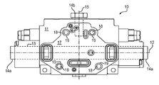
- FIG. 3 b is a top view of the valve section illustrated in FIG. 3 a;
- FIG. 3 c is an end view of the valve section illustrated in FIG. 3 a ;
- FIG. 4 is side elevation view of a second embodiment of the invention, which is similar to the valve section illustrated in FIG. 3 a but with modifications.
- FIG. 1 illustrates a prior art hydraulic valve section 10 .
- the valve section 10 is one section of a complete sectional hydraulic valve (not shown) that includes multiple sections secured together by tie rods (not shown).
- the valve section 10 includes a cast and machined metal housing 11 having a longitudinal axis 12 .
- a main control valve spool bore 13 extends along the longitudinal axis 12 from side to side through the housing 11 and is closed by threaded end caps 14 a .
- the housing 11 also has a vertical axis 15 , and a compensator spool blind bore 16 extends along the vertical axis 15 and is closed by threaded end cap 14 b .
- a main control valve spool (not shown) is slidably disposed in the main control valve spool bore 13
- a compensator spool (not shown) is slidably disposed in the compensator spool bore 16 .
- the housing 11 also includes a machined substantially planar surface 17 , and a plurality of tie rod holes 18 extend from the surface 17 completely through the housing 11 in a direction substantially perpendicular to the planar surface 17 .
- flat annular washer shaped shims 19 are provided at the location of each hole 18 .
- a tie rod extends through each hole 18 and through its associated shim 19 . The shims 19 are placed onto the tie rods during the assembly process, and the tie rods are torqued to secure the valve sections together under stress in a fluid tight manner.
- the thickness of the shims 19 creates a small gap between the valve sections, and this prevents or minimizes stress being applied to the housing 11 at the location of the spool bores 13 and 15 to prevent or minimize distortion of the spool bores 13 and 15 .
- the disadvantage of the shims 19 is that it may be difficult to control the assembly process, since the shims need to be very thin (for example, on the order of 0.001 inch) and it is difficult to assure that just one shim or other prescribed number of shims gets assembled at a time. This is especially true when assembling in the presence of hydraulic oils since the oil may tend to cause the shims to stick together and since the shims are very thin.
- FIG. 2 illustrates a prior art hydraulic valve section 20 .
- the valve section 20 is one section of a complete sectional hydraulic valve (not shown) that includes multiple sections secured together by tie rods (not shown).
- the valve section 20 includes a cast and machined metal housing 21 having a longitudinal axis 22 .
- a main control valve spool bore 23 extends along the longitudinal axis 22 from side to side through the housing 21 and is closed by threaded end caps (not shown).
- the housing 21 also has a vertical axis 25 , and a compensator spool blind bore (not shown) extends parallel to the axis 25 and is closed by a threaded end cap (not shown).
- a main control valve spool (not shown) is slidably disposed in the main control valve spool bore 23
- a compensator spool (not shown) is slidably disposed in the compensator spool bore.
- the housing 21 also includes a machined substantially planar assembly surface 27 , and a plurality of tie rod holes 28 extend from the surface 27 completely through the housing 21 in a direction substantially perpendicular to the planar surface 27 .
- a single relief slot 29 is provided.
- the relief slot 29 extends longitudinally across the surface 27 of the valve section 20 , and the relief slot 29 has a depth (into the plane of the surface 27 ) that is very shallow and on the order of magnitude of the thickness of one or more of the shims described above in connection with FIG. 1 .
- the vertical width of the slot 29 is substantially greater than the diameter of the main spool bore 23 .
- the disadvantage with the single relief slot 29 is that the amount of bearing area on the section 20 seal area gets smaller as the area of the slot 29 gets larger.
- the small gap that is created may allow for distortion of the section 20 when under pressure thus creating higher stresses in that part of the section 20 , than if the small gap were not there.
- a third way to minimize distortion in valve spool bores is by honing the hydraulic sectional main control valve spool bore as a complete assembly.
- the spool bore gets manufactured to its final size after the individual valve sections of the hydraulic sectional valve have been assembled with the tie rods and torqued. This guarantees that any spool bore distortion that occurred during assembly doesn't adversely affect the spool to spool bore fit.
- the disadvantage of this method is that it may be more difficult and/or more costly in comparison with the above described shims and single slot.
- a first preferred embodiment of the present invention provides a hydraulic valve section 30 .
- the valve section 30 is one section of a complete sectional hydraulic valve (not shown) that includes multiple sections secured together by tie rods (not shown).
- the valve section 30 includes a cast and machined metal housing 31 having a longitudinal axis 32 .
- a main control valve spool bore (not shown) extends along the longitudinal axis 32 from side to side through the housing 31 and is closed by threaded end caps (not shown).
- the housing 31 also has a vertical axis 35 , and a compensator spool blind bore (not shown) extends along or parallel to the axis 35 .
- a main control valve spool (not shown) is slidably disposed in the main control valve spool bore 33
- a compensator spool (not shown) is slidably disposed in the compensator spool bore.
- the housing 31 also includes a machined substantially planar surface 37 , and a plurality of tie rod holes 38 extend from the surface 37 completely through the housing 31 in a direction substantially perpendicular to the planar surface 37 .
- first and second relief slots 39 a and 39 b are provided.
- the first relief slot 39 a extends longitudinally from side to side across surface 37 of the valve section 30 , and the relief slot 39 a has a depth in a direction perpendicular to the surface 37 that is very shallow and on an order of magnitude of the thickness of one or more of the shims described above in connection with FIG. 1 .
- the second relief slot 39 b extends vertically from the top of the valve section 30 substantially perpendicular to the direction of the first relief slot 39 a , and the relief slot 39 b preferably does not extend vertically to the bottom of the valve section 30 .
- the second relief slot 39 b also has a depth that is very shallow and on the order of magnitude of the thickness of one or more of the shims described above in connection with FIG. 1 , and the depth of the second relief slot 39 b is preferably substantially equal to the depth of the first relief slot 39 a .
- a preferable depth for this slot in relatively high pressure settings is between 0.0005 inches and 0.002 inches. In low pressure settings, this depth may be increased which makes manufacturing easier.
- the second relief slot 39 b preferably terminates a distance from the first relief slot 39 a .
- the width of the relief slots is preferably between 10% and 50% wider than the width of the respective spool bores.
- the relief slots are 10-20% wider, and in other embodiments, relief slots are 20-50% wider.
- a portion of surface 37 is positioned between the two spool bores so as to prevent localized distortion.
- FIG. 4 is a view similar to FIG. 3 a , but illustrating a second embodiment of the invention which is similar to the first embodiment valve section with minor modifications.
- the valve section 40 is one section of a complete sectional hydraulic valve (not shown) that includes multiple sections secured together by tie rods (not shown).
- the valve section 40 includes a cast and machined metal housing 41 having a longitudinal axis 42 .
- a main control valve spool bore 43 extends along the longitudinal axis 42 from side to side through the housing 41 and is closed by threaded end caps (not shown).
- the housing 41 also has a vertical axis 45 , and a compensator spool blind bore 46 extends along the vertical axis 45 .
- a main control valve spool (not shown) is slidably disposed in the main control valve spool bore 43
- a compensator spool (not shown) is slidably disposed in the compensator spool bore 46 .
- the housing 41 also includes a machined substantially planar surface 47 , and a plurality of tie rod holes 48 extend from the surface 47 completely through the housing 41 in a direction substantially perpendicular to the planar surface 47 .
- first and second relief slots 49 a and 49 b are provided.
- the first relief slot 49 a extends longitudinally from side to side across surface 47 of the valve section 40 , and the relief slot 49 a has a depth in a direction perpendicular to the surface 47 that is very shallow and on an order of magnitude of the thickness of one or more of the shims described above in connection with FIG. 1 .
- the second relief slot 49 b extends vertically from the top of the valve section 40 substantially perpendicular to the direction of the first relief slot 49 a , and the relief slot 49 b preferably does not extend vertically to the bottom of the valve section 40 .
- the second relief slot 49 b also has a depth that is very shallow and on an order of magnitude of the thickness of one or more of the shims described above in connection with FIG. 1 , and the depth of the second relief slot 49 b is preferably substantially equal to the depth of the first relief slot 49 a .
- a preferable depth for this slot in relatively high pressure settings is between 0.0005 inches and 0.002 inches. In low pressure settings, this depth may be increased which makes manufacturing easier.
- the second relief slot 49 b preferably terminates a distance from the first relief slot 49 a .
- the width of the relief slots is preferably between 10% and 50% wider than the width of the respective spool bores.
- the relief slots are 10-20% wider, and in other embodiments, relief slots are 20-50% wider.
- a portion of surface 37 is positioned between the two spool bores so as to prevent localized distortion.
- This embodiment also depicts rounded corners at the terminal end of slot 49 b . These rounded corners are a product of machining the slot with a surface rotary milling bit.
Landscapes
- Engineering & Computer Science (AREA)
- General Engineering & Computer Science (AREA)
- Mechanical Engineering (AREA)
- Physics & Mathematics (AREA)
- Fluid Mechanics (AREA)
- Valve Housings (AREA)
Abstract
Description
Claims (20)
Priority Applications (1)
| Application Number | Priority Date | Filing Date | Title |
|---|---|---|---|
| US15/302,551 US9683586B2 (en) | 2014-04-30 | 2015-04-30 | Hydraulic sectional control valve with multiple relief slots |
Applications Claiming Priority (3)
| Application Number | Priority Date | Filing Date | Title |
|---|---|---|---|
| US201461986183P | 2014-04-30 | 2014-04-30 | |
| US15/302,551 US9683586B2 (en) | 2014-04-30 | 2015-04-30 | Hydraulic sectional control valve with multiple relief slots |
| PCT/US2015/028452 WO2015168369A1 (en) | 2014-04-30 | 2015-04-30 | Hydraulic sectional control valve with multiple relief slots |
Publications (2)
| Publication Number | Publication Date |
|---|---|
| US20170023026A1 US20170023026A1 (en) | 2017-01-26 |
| US9683586B2 true US9683586B2 (en) | 2017-06-20 |
Family
ID=53180831
Family Applications (1)
| Application Number | Title | Priority Date | Filing Date |
|---|---|---|---|
| US15/302,551 Expired - Fee Related US9683586B2 (en) | 2014-04-30 | 2015-04-30 | Hydraulic sectional control valve with multiple relief slots |
Country Status (3)
| Country | Link |
|---|---|
| US (1) | US9683586B2 (en) |
| CA (1) | CA2946880A1 (en) |
| WO (1) | WO2015168369A1 (en) |
Families Citing this family (1)
| Publication number | Priority date | Publication date | Assignee | Title |
|---|---|---|---|---|
| US20180109713A1 (en) * | 2016-10-15 | 2018-04-19 | SMPL Inc. | System and method for evenly-scattered adaptable subject lighting for mobile device photography |
Citations (11)
| Publication number | Priority date | Publication date | Assignee | Title |
|---|---|---|---|---|
| US3406989A (en) | 1965-06-11 | 1968-10-22 | Westinghouse Bremsen Apparate | Combined multiple fluid distribution panel blocks and connector means therefor |
| US3722540A (en) | 1971-05-20 | 1973-03-27 | Commercial Shearing | Sectional control valves |
| US3840047A (en) | 1971-10-28 | 1974-10-08 | Dowty Mining Equipment Ltd | Hydraulic apparatus |
| DE3503070A1 (en) | 1985-01-30 | 1986-08-07 | Robert Bosch Gmbh, 7000 Stuttgart | Directional control valve intended for block type of construction |
| US20060038399A1 (en) * | 2004-08-19 | 2006-02-23 | Flow International Corporation | High fatigue life fittings for high-pressure fluid systems |
| US7021332B2 (en) * | 2004-03-26 | 2006-04-04 | Husco International, Inc. | Hydraulic valve section with reduced bore distortion |
| US7096889B1 (en) * | 2003-04-01 | 2006-08-29 | Curtis Roys | Fluid divider block suitable for use at high pressures |
| US20110081268A1 (en) * | 2009-08-13 | 2011-04-07 | Brian Ochoa | Pump body |
| US8220495B2 (en) * | 2007-05-31 | 2012-07-17 | Fujikin Incorporated | Fluid control apparatus and method for assembling the same |
| US8465268B2 (en) * | 2010-09-10 | 2013-06-18 | Phoinix Global LLC | Compression clamp for a modular fluid end for a multiplex plunger pump |
| US9212781B2 (en) * | 2003-04-01 | 2015-12-15 | Compressor Products International Llc | Fluid divider block suitable for use at high pressures |
-
2015
- 2015-04-30 CA CA2946880A patent/CA2946880A1/en not_active Abandoned
- 2015-04-30 WO PCT/US2015/028452 patent/WO2015168369A1/en not_active Ceased
- 2015-04-30 US US15/302,551 patent/US9683586B2/en not_active Expired - Fee Related
Patent Citations (11)
| Publication number | Priority date | Publication date | Assignee | Title |
|---|---|---|---|---|
| US3406989A (en) | 1965-06-11 | 1968-10-22 | Westinghouse Bremsen Apparate | Combined multiple fluid distribution panel blocks and connector means therefor |
| US3722540A (en) | 1971-05-20 | 1973-03-27 | Commercial Shearing | Sectional control valves |
| US3840047A (en) | 1971-10-28 | 1974-10-08 | Dowty Mining Equipment Ltd | Hydraulic apparatus |
| DE3503070A1 (en) | 1985-01-30 | 1986-08-07 | Robert Bosch Gmbh, 7000 Stuttgart | Directional control valve intended for block type of construction |
| US7096889B1 (en) * | 2003-04-01 | 2006-08-29 | Curtis Roys | Fluid divider block suitable for use at high pressures |
| US9212781B2 (en) * | 2003-04-01 | 2015-12-15 | Compressor Products International Llc | Fluid divider block suitable for use at high pressures |
| US7021332B2 (en) * | 2004-03-26 | 2006-04-04 | Husco International, Inc. | Hydraulic valve section with reduced bore distortion |
| US20060038399A1 (en) * | 2004-08-19 | 2006-02-23 | Flow International Corporation | High fatigue life fittings for high-pressure fluid systems |
| US8220495B2 (en) * | 2007-05-31 | 2012-07-17 | Fujikin Incorporated | Fluid control apparatus and method for assembling the same |
| US20110081268A1 (en) * | 2009-08-13 | 2011-04-07 | Brian Ochoa | Pump body |
| US8465268B2 (en) * | 2010-09-10 | 2013-06-18 | Phoinix Global LLC | Compression clamp for a modular fluid end for a multiplex plunger pump |
Non-Patent Citations (1)
| Title |
|---|
| International Search Report and Written Opinion for corresponding Patent Application No. PCT/US2015/028452 dated Aug. 11, 2015. |
Also Published As
| Publication number | Publication date |
|---|---|
| CA2946880A1 (en) | 2015-11-05 |
| WO2015168369A1 (en) | 2015-11-05 |
| US20170023026A1 (en) | 2017-01-26 |
Similar Documents
| Publication | Publication Date | Title |
|---|---|---|
| EP3311015B1 (en) | Longitudinally adjustable connecting rod | |
| US9410595B2 (en) | Damping valve for shock absorber | |
| DE112018003806B4 (en) | shock absorber | |
| US9719609B2 (en) | Change-over valve | |
| EP3161279B1 (en) | Hydraulic valve for an internal combustion engine | |
| EP2550437B1 (en) | Control valve of a phasing device for adjusting the phase of a camshaft relative to the crankshaft in an internal combustion engine | |
| US10352390B2 (en) | Damper and method of assembling damper | |
| DE112018004751B4 (en) | shock absorber | |
| AT517217A4 (en) | LENGTH-ADJUSTABLE CONNECTING ROD | |
| EP2998627A1 (en) | Hydraulic valve | |
| US20190024806A1 (en) | Spool valve | |
| US9683586B2 (en) | Hydraulic sectional control valve with multiple relief slots | |
| EP2628959A2 (en) | Servo valve | |
| DE102007029807A1 (en) | Polrohr and actuating magnet with such a pole tube | |
| EP3014129A1 (en) | Hydraulic cylinder having a piston rod | |
| KR101463800B1 (en) | Gasket | |
| WO2013174531A1 (en) | Control valve for a camshaft adjuster | |
| EP1662150B1 (en) | Directional control valve block | |
| US5123450A (en) | Fluid control valve | |
| DE19856018A1 (en) | Unlockable check valve for very high system pressures | |
| DE102014213880B4 (en) | Bearing ring of a bearing, in particular a rolling bearing | |
| DE112016000514T5 (en) | fluid damper | |
| US10753481B2 (en) | Regulating valve, valve body, and valve stem | |
| US10100686B2 (en) | Hydraulic camshaft adjuster, use, and method for assembling an at least two-part rotor of a hydraulic camshaft adjuster | |
| DE102011084944A1 (en) | Integration of an axial bearing in a rotor |
Legal Events
| Date | Code | Title | Description |
|---|---|---|---|
| AS | Assignment |
Owner name: PARKER-HANNIFIN CORPORATION, OHIO Free format text: ASSIGNMENT OF ASSIGNORS INTEREST;ASSIGNOR:COOLIDGE, GREGORY;REEL/FRAME:039963/0613 Effective date: 20150506 |
|
| STCF | Information on status: patent grant |
Free format text: PATENTED CASE |
|
| AS | Assignment |
Owner name: PARKER INTANGIBLES, LLC, OHIO Free format text: ASSIGNMENT OF ASSIGNORS INTEREST;ASSIGNOR:PARKER-HANNIFIN CORPORATION;REEL/FRAME:045843/0859 Effective date: 20180405 |
|
| MAFP | Maintenance fee payment |
Free format text: PAYMENT OF MAINTENANCE FEE, 4TH YEAR, LARGE ENTITY (ORIGINAL EVENT CODE: M1551); ENTITY STATUS OF PATENT OWNER: LARGE ENTITY Year of fee payment: 4 |
|
| FEPP | Fee payment procedure |
Free format text: MAINTENANCE FEE REMINDER MAILED (ORIGINAL EVENT CODE: REM.); ENTITY STATUS OF PATENT OWNER: LARGE ENTITY |
|
| LAPS | Lapse for failure to pay maintenance fees |
Free format text: PATENT EXPIRED FOR FAILURE TO PAY MAINTENANCE FEES (ORIGINAL EVENT CODE: EXP.); ENTITY STATUS OF PATENT OWNER: LARGE ENTITY |
|
| STCH | Information on status: patent discontinuation |
Free format text: PATENT EXPIRED DUE TO NONPAYMENT OF MAINTENANCE FEES UNDER 37 CFR 1.362 |
|
| FP | Lapsed due to failure to pay maintenance fee |
Effective date: 20250620 |