US968003A - Windmill. - Google Patents
Windmill. Download PDFInfo
- Publication number
- US968003A US968003A US54570710A US1910545707A US968003A US 968003 A US968003 A US 968003A US 54570710 A US54570710 A US 54570710A US 1910545707 A US1910545707 A US 1910545707A US 968003 A US968003 A US 968003A
- Authority
- US
- United States
- Prior art keywords
- wind
- wheel
- axle
- wheels
- axles
- Prior art date
- Legal status (The legal status is an assumption and is not a legal conclusion. Google has not performed a legal analysis and makes no representation as to the accuracy of the status listed.)
- Expired - Lifetime
Links
- 230000004888 barrier function Effects 0.000 description 7
- 238000007664 blowing Methods 0.000 description 4
- 241001541997 Allionia Species 0.000 description 1
- 241001522296 Erithacus rubecula Species 0.000 description 1
- 240000008881 Oenanthe javanica Species 0.000 description 1
- 230000007547 defect Effects 0.000 description 1
- 230000001681 protective effect Effects 0.000 description 1
- 230000000284 resting effect Effects 0.000 description 1
Images
Classifications
-
- F—MECHANICAL ENGINEERING; LIGHTING; HEATING; WEAPONS; BLASTING
- F04—POSITIVE - DISPLACEMENT MACHINES FOR LIQUIDS; PUMPS FOR LIQUIDS OR ELASTIC FLUIDS
- F04D—NON-POSITIVE-DISPLACEMENT PUMPS
- F04D25/00—Pumping installations or systems
- F04D25/16—Combinations of two or more pumps ; Producing two or more separate gas flows
- F04D25/166—Combinations of two or more pumps ; Producing two or more separate gas flows using fans
Definitions
- W'iiid'mills. asat present constructed and operated are of'limited power owing to the fact that they must be mounted upon towers which provide a very unstable support for.
- the mill irthe bladesV are provided with a suiiicient wind surface to produce any very f Y great amount of power.
- Another source of weakness in ordinary wind mills arises from the fact that they must be shifted to present an effective face to the wind, thereby i preventing the tower from being constructed to ali'oi'd suflicient support to a mill having a large wind surface.
- l y y It is the principal Vobject of my invention to avoid these defects by mounting my mill near the ground. f
- Another object is to construct a mill with two operating wheelsV which shall be setwitli their axles at right angles to each other and provide the mill with shields for directing the wind upon the vaiies.
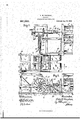
- Figure .1 is a pla-n yofmy improved wind mill with parts broken away.
- Fig. 2 is a vertical section on the line :2-2 of Fig. 1.
- the drawings 5 and 6 are'wind wheels which are revolubly mounted in suitable frame work k7 placed upon the ground ⁇ 8 by means of axles -9v and l0, which axles are revolubly mounted in said frame work.
- These axles lie in a horizontal plane and the wheels are ot' any desired length and are preferably of the same length, and they are set with their axles in planes at right angles to each other. IVhere only one wheel is used it will be set with its axle on a li-nc at rig it angles with the prevailing direction of the wind in the locality.
- the blades 11 are preferably curved as best shown in Fig. 2, but may be straight blades if desired.
- EX- tending along in front of the wind wheels are permanent barriers 12 which extend upwardly lto the center of the wheel and extend preferably beneath the wheel as best shown in Fig. 2. These permanent barriers prevent the wind Yfrom striking the lower portion of the wheel when the wind is bowing in the direction opposite to that indi- WiNDMILL.
- piveted protective aprons 15 Adjacent to the top of the permanent. barriers are piveted protective aprons 15 which normally lie in the position shown iii Fig.v
- Axle t is provided with a collar 17 which is rigidly secured theretorat a distance from iis inner end and with a spline 1S which extends from the coliar to near the end of said axle.
- a collar 17 which is rigidly secured theretorat a distance from iis inner end and with a spline 1S which extends from the coliar to near the end of said axle.
- Upon tlieend o the axle and spline is mounted the' movable member 19 of a clutch.
- the other member .10 of the clutch is rigidly secured upon a stub shaft :21 on the inner end of which is mounted the bevel gear 22. ⁇ between collar 17 and. the movable member of the clutch holds the two members of the A.
- coiled spring Zij mounted on shaft 2l rotates its shaft more 'rapidly than wheel 5 rotates axle 9.
- Bevel gear 22 meshes with bevel gear 24: mounted ⁇ iiponthe driven shaft 25, from which power is taken to operate the machinery not shown.
- Shatt 25 has secured upon its inner end a rigid clutch member 2G.
- Axle l() is provided with a collar :'27, a spline 2S and amovable clateh member 29.
- deflectors 13 would have the free ⁇ ends thereotl resting upon the ground.
- freeend is meant the end opposite the pivotal connection which connection unites the detlectors to the timbers of the frame.
- This movable clutch4 Yloi-ce of the wind can be utilized no matter in what 'direction thewind is blowing.
- a wind motor comprising two wind wheels having horizontal axles mounted near the surtace ofthe ground, the axle of one wind wheel being in a vertical plane at ⁇ rielit angles to the Vertical plane of the axe of the other wheel; a driven axle in aliiienient with the axle of one of the wheels; a clutch normally connecting thel driven shaft to the axle of the wheel; a bevel gear mountedV upon said driven shaft; a stub shatt mounted in ahmeld with the axle of the other wheel; a clutch normally Y connecting the stub axle with the axle of said last wheel; a beiel gear mounted on said stub shaft; said bevel gear meshing with the gear on the driven shaft; permanent barriers extending upwardly from the surface of the ground to near the center of Y the wheels; other barriers extending'iipwardly from the surface of the ground between the Wheels; movable deflectors pivotally mounted at the rear of the wheels on a line substantially on the same plane with the top of the permanent barriers
Landscapes
- Engineering & Computer Science (AREA)
- Mechanical Engineering (AREA)
- General Engineering & Computer Science (AREA)
- Wind Motors (AREA)
Description
- ROBIN'A W. VAUGHAN, OF LOS ANGELES, CALIFORNIA.
i To allwhomitmayfconcern: v l Y `Be it known that I, Ronin IV. VaUGi-IAN, acitizen of the United States, residing in the city of Los Angeles7 county of Los An-l geles, State of California,` have invented new and useful Improvements in f'iiidinills7 of whichtlie following is a speciicatioii.
W'iiid'mills. asat present constructed and operated are of'limited power owing to the fact that they must be mounted upon towers which provide a very unstable support for.
the mill irthe bladesV are provided with a suiiicient wind surface to produce any very f Y great amount of power. Another source of weakness in ordinary wind mills arises from the fact that they must be shifted to present an effective face to the wind, thereby i preventing the tower from being constructed to ali'oi'd suflicient support to a mill having a large wind surface. l y y It is the principal Vobject of my invention to avoid these defects by mounting my mill near the ground. f
Another objectis to construct a mill with two operating wheelsV which shall be setwitli their axles at right angles to each other and provide the mill with shields for directing the wind upon the vaiies.
In the drawings accompanying this `application and forming a part thereof; Figure .1 is a pla-n yofmy improved wind mill with parts broken away. Fig. 2 is a vertical section on the line :2-2 of Fig. 1.
Iii the drawings 5 and 6 are'wind wheels which are revolubly mounted in suitable frame work k7 placed upon the ground `8 by means of axles -9v and l0, which axles are revolubly mounted in said frame work. These axles lie in a horizontal plane and the wheels are ot' any desired length and are preferably of the same length, and they are set with their axles in planes at right angles to each other. IVhere only one wheel is used it will be set with its axle on a li-nc at rig it angles with the prevailing direction of the wind in the locality. The blades 11 are preferably curved as best shown in Fig. 2, but may be straight blades if desired. EX- tending along in front of the wind wheels are permanent barriers 12 which extend upwardly lto the center of the wheel and extend preferably beneath the wheel as best shown in Fig. 2. These permanent barriers prevent the wind Yfrom striking the lower portion of the wheel when the wind is bowing in the direction opposite to that indi- WiNDMILL.
ally mounted movable deliectors-13 which when Vthe wind is blowing inthe direction showiiby the arrows in Fig. 2 are se :tired to the frame work in any suitable n aimer so as to protect the upper part of the wheel and deiiect the wind downwardly and onto' the lower haltl of thewheel, as shown in Fig; 2.
position below the laxle of the wheel as shown in dotted lines in the lower part` of the left hand portion of Fig. 2. -When it is desired to use these deflectors, as a protecting covering for the wheel, they are secured in the position shown in the upper part of Fig. 2, as shown in dotted lines. In the drawings I have shown detiectors 13 in their operative position and secured -in the framework by means of bolts l which pass through the frame work and into the ends of the deflectors as shown in dotted and full lines in Fig. 1, but any other means ot fastening them may be used. Y
Adjacent to the top of the permanent. barriers are piveted protective aprons 15 which normally lie in the position shown iii Fig.v
v p atented' A110'. 23, V1910. Application tiled February 24, 1910. Seri'allo. 545,707.
These delectors, when the wind iskblowing in the opposite direction, rest in the an opposite direction tol the arrows. I
have also provided vertical barriers 16 between tlie wind wheels to dellect the wind upon the wheels that otherwise would pass .between them Awhen the wind is blowing angularly onto both wheels.
Axle t) is provided with a collar 17 which is rigidly secured theretorat a distance from iis inner end and with a spline 1S which extends from the coliar to near the end of said axle. Upon tlieend o the axle and spline is mounted the' movable member 19 of a clutch. The other member .10 of the clutch is rigidly secured upon a stub shaft :21 on the inner end of which is mounted the bevel gear 22.` between collar 17 and. the movable member of the clutch holds the two members of the A. coiled spring Zij mounted on shaft 2l rotates its shaft more 'rapidly than wheel 5 rotates axle 9. Bevel gear 22 meshes with bevel gear 24: mounted` iiponthe driven shaft 25, from which power is taken to operate the machinery not shown. Shatt 25 has secured upon its inner end a rigid clutch member 2G. a. Axle l() is provided with a collar :'27, a spline 2S and amovable clateh member 29. member is normally held by spring 30 in engagenient with the xed clutchvnieniber on shaft l f In the operation of my wind wheels, when the wind isblowing directly against one of .the whcels,'that is in a direction at right :angles to the axle thereof, the other wheel would be: inoperative, but when the wind is portion of the wheels the dellectors 13 must be raised. so as to deflect the wind downwardly as shown by the arrows in F ig. 2,
. but that wheirthewind is blowing in the ropposite direction, deflectors 13 would have the free `ends thereotl resting upon the ground.. By freeend is meant the end opposite the pivotal connection which connection unites the detlectors to the timbers of the frame. It will also be understood that iii those situations where the direction of the wind is almost constantly in one direction only one wind wheel is required, but I'prefer the use of two with their axles set at. right angles to each other, as thereby the claim is;
This movable clutch4 Yloi-ce of the wind can be utilized no matter in what 'direction thewind is blowing.
llaving described my invention whatI A wind motor comprising two wind wheels having horizontal axles mounted near the surtace ofthe ground, the axle of one wind wheel being in a vertical plane at `rielit angles to the Vertical plane of the axe of the other wheel; a driven axle in aliiienient with the axle of one of the wheels; a clutch normally connecting thel driven shaft to the axle of the wheel; a bevel gear mountedV upon said driven shaft; a stub shatt mounted in ahnement with the axle of the other wheel; a clutch normally Y connecting the stub axle with the axle of said last wheel; a beiel gear mounted on said stub shaft; said bevel gear meshing with the gear on the driven shaft; permanent barriers extending upwardly from the surface of the ground to near the center of Y the wheels; other barriers extending'iipwardly from the surface of the ground between the Wheels; movable deflectors pivotally mounted at the rear of the wheels on a line substantially on the same plane with the top of the permanent barriers; means toseeure the free ends of the deflectors in' the position to protect the top portion ot' the wheel Afrom the force of the Wind and to detlect the wind striking the detlector upon the bottoni portion of the wheel; and
pivoted protecting aprons in front of said wheels. Y
In witness that I claim the foregoing I have hereunto subscribed my name this 19th day of February, 1910.
ROBIN W'. VAUGHAN. Witnesses: a
G. E. HARPHAM, S. B. AUSTIN.
Priority Applications (1)
| Application Number | Priority Date | Filing Date | Title |
|---|---|---|---|
| US54570710A US968003A (en) | 1910-02-24 | 1910-02-24 | Windmill. |
Applications Claiming Priority (1)
| Application Number | Priority Date | Filing Date | Title |
|---|---|---|---|
| US54570710A US968003A (en) | 1910-02-24 | 1910-02-24 | Windmill. |
Publications (1)
| Publication Number | Publication Date |
|---|---|
| US968003A true US968003A (en) | 1910-08-23 |
Family
ID=3036394
Family Applications (1)
| Application Number | Title | Priority Date | Filing Date |
|---|---|---|---|
| US54570710A Expired - Lifetime US968003A (en) | 1910-02-24 | 1910-02-24 | Windmill. |
Country Status (1)
| Country | Link |
|---|---|
| US (1) | US968003A (en) |
-
1910
- 1910-02-24 US US54570710A patent/US968003A/en not_active Expired - Lifetime
Similar Documents
| Publication | Publication Date | Title |
|---|---|---|
| US2619363A (en) | Vehicle splash guard | |
| US2169079A (en) | Trenching machine | |
| CN113120100A (en) | Method for enhancing stability of automobile | |
| US929198A (en) | Deflector-hood control for tangential water-wheels. | |
| US805965A (en) | Dredging apparatus. | |
| US985131A (en) | Windmill. | |
| US729650A (en) | Traveling sprinkler. | |
| US997819A (en) | Propeller-wheel. | |
| US386684A (en) | Windmill | |
| US288021A (en) | Fly-fan | |
| US519362A (en) | Windmill | |
| DE212014000161U1 (en) | power plant | |
| SE467095B (en) | BLADE PROTECTION BY CLEANING DEVICE | |
| US489008A (en) | Snow-plow | |
| US1236811A (en) | Armored vehicle. | |
| US1423717A (en) | Current motor | |
| US880518A (en) | Windmill. | |
| US648968A (en) | Windmill. | |
| US1537465A (en) | Louver-type baffle plate | |
| US1236626A (en) | Emergency-truck. | |
| US420879A (en) | And henry g | |
| US917942A (en) | Windmill. | |
| US1670099A (en) | Wind motor | |
| US557893A (en) | Windmill | |
| US138593A (en) | Improvement in wind-wheel powers |