US9669650B2 - Structure of whiteboard - Google Patents
Structure of whiteboard Download PDFInfo
- Publication number
- US9669650B2 US9669650B2 US14/408,960 US201414408960A US9669650B2 US 9669650 B2 US9669650 B2 US 9669650B2 US 201414408960 A US201414408960 A US 201414408960A US 9669650 B2 US9669650 B2 US 9669650B2
- Authority
- US
- United States
- Prior art keywords
- plate
- locking
- rim
- main body
- bottom casing
- Prior art date
- Legal status (The legal status is an assumption and is not a legal conclusion. Google has not performed a legal analysis and makes no representation as to the accuracy of the status listed.)
- Expired - Fee Related, expires
Links
Images


Classifications
-
- B—PERFORMING OPERATIONS; TRANSPORTING
- B43—WRITING OR DRAWING IMPLEMENTS; BUREAU ACCESSORIES
- B43L—ARTICLES FOR WRITING OR DRAWING UPON; WRITING OR DRAWING AIDS; ACCESSORIES FOR WRITING OR DRAWING
- B43L5/00—Drawing boards
-
- G—PHYSICS
- G09—EDUCATION; CRYPTOGRAPHY; DISPLAY; ADVERTISING; SEALS
- G09B—EDUCATIONAL OR DEMONSTRATION APPLIANCES; APPLIANCES FOR TEACHING, OR COMMUNICATING WITH, THE BLIND, DEAF OR MUTE; MODELS; PLANETARIA; GLOBES; MAPS; DIAGRAMS
- G09B5/00—Electrically-operated educational appliances
- G09B5/02—Electrically-operated educational appliances with visual presentation of the material to be studied, e.g. using film strip
-
- B—PERFORMING OPERATIONS; TRANSPORTING
- B43—WRITING OR DRAWING IMPLEMENTS; BUREAU ACCESSORIES
- B43L—ARTICLES FOR WRITING OR DRAWING UPON; WRITING OR DRAWING AIDS; ACCESSORIES FOR WRITING OR DRAWING
- B43L1/00—Repeatedly-usable boards or tablets for writing or drawing
Definitions
- the present invention relates to a kind of electronic board, which is generally used in classrooms.
- both an electronic board and a traditional blackboard are used at same time.
- the electronic board overlaps in front of the blackboard, or the electronic board is hidden behind a door. That is not convenient for using, and influences the writing of teachers, and soils the classroom, and also brings some dangers to teachers and students.
- the rims and the connectors are made of aluminium profile and aluminium casting, the board will be very heavy in weight, and increase materials consumption, energy consumption and carbon emission, and cannot be waterproof, and will be not safe. This kinds of above-mentioned boards can not meet the requirements of the boards of college, high school and primary school.
- the technical problem that the present invention needs to overcome the defect that traditional electronic whiteboard is very heavy in weight and cannot be waterproof, then to provide an electronic board with stable structure, and its shape will not change under using environment, with the functions of anti-water and anti-dust and safety in use.
- An electronic board comprises a panel, four rims and four connectors.
- the panel is a rectangle.
- the panel comprises a writable pre-coating layer located on top thereof, a foaming layer located in the middle thereof and a back plate located on bottom thereof. A number of square holes are bored in a row at the edge of the back plate.
- the each rim of the four rims has the same structure.
- the each rim comprises a rim main body and a number of locking pieces.
- the rim main body comprises a top plate, a light filter plate, an upper plate, a side plate and a number of locking holes.
- the upper plate is under the top plate.
- the light filter plate is connected between the end of the top plate and the end of the upper plate by melting.
- the side plate and the upper plate are vertical.
- An inserting plate is vertically extended outwards from the side plate.
- a number of barbed bars are extended from the distal end of the inserting plate.
- a locking plate is vertically extended downwards from the rear end of the inserting plate.
- a number of toothed bars are extended from the locking plate.
- the locking pieces are locked at the lower ends of the locking plates.
- the each locking piece comprises a connecting portion at the upper position thereof.
- the connecting portion is hollow.
- a number of toothed grooves are defined on the inner wall of the connecting portion.
- a supporting portion is formed at the lower end of the connecting portion.
- the each connector of the four connectors has the same structure.
- the each connector comprises a bottom casing and a top casing.
- the bottom casing comprises a bottom casing main body.
- a first linking portion is located at one side of the bottom casing main body.
- a first fixing plate is vertically extended upwards from the edge of the first linking portion.
- a number of first screw holes are bored on the first fixing plate, which are corresponding to the locking holes of the rim.
- a second linking portion is located at the other site of the bottom casing main body.
- a second fixing plate is vertically extended upwards from the edge of the second linking portion.
- a number of second screw holes are bored on the second fixing plate, which are corresponding to the locking holes of the rim.
- the top casing comprises a top cover.
- a lateral plate is downwards bent and extended from the outer edge of the top cover.
- a sealing strip is pasted at the position of the inner edge of the sealing strip contacting the writable pre-coating layer.
- the foaming layer is a layer of the XPS foam board with high strength.
- the back plate is a layer of galvanized steel board.
- the end of the top plate, the light filter plate and the end of the upper plate are formed as a single body in one step by high temperature melting.
- the further improvement of the technical solution is: two protruding lugs are vertically extended from the side plate, and a slot is located between the two protruding lugs.
- the electronic board in accordance with the present invention has many advantages than prior arts.
- the top plate and the light filter plate, and the upper plate are formed respectively with two different kinds of high polymer materials in one step by high temperature melting. Therefore, the top plate, the light filter plate and the upper plate have been formed a single body, so that structure not only meets the requirement of anti-water but also enhances the stability.
- a sealing strip is pasted at the position of the inner edge of the sealing strip contacting the writable pre-coating layer, for the purpose of anti-water and anti-dust.
- the inserting plates are inserted into the foaming layer, and the locking plates and the locking pieces cooperate to lock the back plate, thus the four rims are stably fixed to the panel.
- the electronic board is stable in the assembly circumstance, and its structure is stable, and its shape will not change under using environment.
- the electronic board produced in accordance with the present invention is light in weight, and reduces materials consumption, and has a stable structure, and can cost down the production cost.
- the electronic board also has the advantages of anti-water and anti-dust and safety in use.
- the electronic board can be used in the environments of college, high school and primary school, and can meet the requirement of the board in the Future Classroom in the information age.
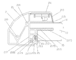
- FIG. 1 is a schematic drawing of the electronic board in accordance with the present invention.
- FIG. 2 is a schematic drawing of the panel and the rim.
- FIG. 3 is a stereogram view of the bottom casing.
- FIG. 4 is a stereogram view of the top casing.
- the first embodiment of the electronic board in accordance with the present invention comprises a panel 1 , four rims 2 and four connectors 3 .
- the panel 1 is a rectangle.
- the panel 1 comprises a writable pre-coating layer 11 located on top thereof, a foaming layer 13 located in the middle thereof and a back plate 15 located on bottom thereof.
- the foaming layer 13 is a layer of the XPS foam board with high strength.
- the back plate 15 is a layer of galvanized steel board.
- a number of square holes 151 are bored in a row at the edge of the back plate 15 .
- the writable pre-coating layer 11 and the foaming layer 13 are tightly stuck by pasting some adhesive between just mentioned two layers.
- the foaming layer 13 and the back plate 15 are tightly stuck by pasting some adhesive between just mentioned two layers.
- the each rim 2 of the four rims 2 has the same structure.
- the four rims 2 are made of high polymer material.
- the each rim 2 basically shows linear shape.
- the each rim 2 comprises a rim main body 21 and a number of locking pieces 25 .
- the rim main body 21 comprises a top plate 211 , a light filter plate 213 , an upper plate 215 , a side plate 217 and two locking holes 219 .
- the upper plate 215 is under the top plate 211 .
- the light filter plate 213 is connected between the end of the top plate 211 and the end of the upper plate 215 .
- the top plate 211 and the light filter plate 213 , and the upper plate 215 are formed respectively with two differ kinds of high polymer materials in one step by high temperature melting. Therefore, the top plate 211 , the light filter plate 213 and the upper plate 215 has been formed a single body, so that structure not only meets the requirement of anti-water but also enhances the stability.
- the material of the light filter plate 23 also is able to meet the requirement of permitting the infrared light to pass through.
- the side plate 217 and the upper plate 215 are vertical.
- An inserting plate 2171 is vertically extended outwards from the side plate 217 .
- a number of barbed bars 2173 are extended from the distal end of the inserting plate 2171 .
- a locking plate 2175 is vertically extended downwards from the rear end of the inserting plate 2171 .
- a number of toothed bars 2177 are extended from the locking plate 2175 .
- Two protruding lugs 2179 are vertically extended from the side plate 217 .
- a slot 2181 is located between the two protruding lugs 2179 .
- the locking pieces 25 are locked at the lower ends of the locking plates 2175 .
- the each locking piece 25 comprises a connecting portion 251 at the upper position thereof.
- the connecting portion 251 is hollow.
- a number of toothed grooves 253 are defined on the inner wall of the connecting portion 251 .
- a supporting portion 255 is formed at the lower end of the connecting portion 251 .
- the size of the supporting portion 255 is slightly larger than the size of the connecting portion 251 .
- the toothed bars 2177 of the locking plates 2175 of the rims 2 are hooked into the toothed grooves 253 of the connecting portions 251 of the locking pieces 25 , so the locking pieces 25 are locked to the locking plate 2175 .
- the each connector 3 of the four connectors 3 has the same structure.
- the four connectors 3 are made of high polymer material.
- the each connector 3 comprises a bottom casing 31 and a top casing 35 .
- the bottom casing 31 comprises a bottom casing main body 311 .
- a first linking portion 313 is located at one side of the bottom casing main body 311 .
- a first fixing plate 315 is vertically extended upwards from the edge of the first linking portion 313 .
- Two first screw holes 317 are bored on the first fixing plate 315 , which are corresponding to the two locking holes 219 of the rim 2 .
- a second linking portion 319 is located at the other side of the bottom casing main body 311 .
- a second fixing plate 321 is vertically extended upwards from the edge of the second linking portion 319 .
- Two second screw holes 323 are bored on the second fixing plate 321 , which are corresponding to the two locking holes 219 of the rim 2 .
- the top casing 35 comprises a top cover 351 .
- a lateral plate 353 is downwards bent and extended from the outer edge of the top cover 351 .
- a sealing strip 355 is pasted at the position of the inner edge of the sealing strip 355 contacting the writable pre-coating layer 11 , for the purpose of anti-water and anti-dust.
- the inserting plates 2171 are inserted into the foaming layer 13 , thus the four rims 2 and the panel 1 are difficult to separate, because the barbed bars 2173 of the inserting plates 2171 pierce into and hook the panel 1 .
- the writable pre-coating layer 11 presses the upper plates 215 , at the same time, the back plate 15 is inserted into the slots 2181 , then the locking pieces 25 are inserted through the square holes 151 of the back plate 15 to hook to the locking plates 2175 of the four rims 2 .
- the supporting portions 255 of the locking pieces 25 support the back plate 15 , thus the four rims 2 are stably fixed to the panel 1 .
- each connector 3 is put between two neighboring rims 2 , after using self-tapping screws (not shown in Figs) to insert through the two first screw holes 317 and the two second screw holes 323 , then the self-tapping screws are locked in the locking holes 219 of the rim 2 , thus the four connectors 3 and the four rims 2 can be connected to become an annular integral structure.
- the four connectors 3 are fixed at the four corners of the panel 1 . At last, the top casings 35 are fixed.
- the electronic board in accordance with the present invention has many advantages than prior arts.
- the top plate 211 and the light filter plate 213 , and the upper plate 215 are formed respectively with two different kinds of high polymer materials in one step by high temperature melting. Therefore, the top plate 211 , the light filter plate 213 and the upper plate 215 have been formed a single body, so that structure not only meets the requirement of anti-water but also enhances the stability.
- a sealing strip 355 is pasted at the position of the inner edge of the sealing strip 355 contacting the writable pre-coating layer 11 , for the purpose of anti-water and anti-dust.
- the inserting plates 2171 are inserted into the foaming layer 13 , and the locking plates 2175 and the locking pieces 25 cooperate to lock the back plate 15 , thus the four rims 2 are stably fixed to the panel 1 .
- the electronic board is stable in the assembly circumstance, and its structure is stable, and its shape will not change under using environment.
- the electronic board produced in accordance with the present invention is light in weight, and reduces materials consumption, and has a stable structure, and can cost down the production cost.
- the electronic board also has the advantages of anti-water and anti-dust and safety in use.
- the electronic board can be used in the environments of college, high school and primary school, and can meet the requirement of the board in the Future Classroom in the information age.
Landscapes
- Engineering & Computer Science (AREA)
- Business, Economics & Management (AREA)
- Physics & Mathematics (AREA)
- Educational Administration (AREA)
- Educational Technology (AREA)
- General Physics & Mathematics (AREA)
- Theoretical Computer Science (AREA)
- Casings For Electric Apparatus (AREA)
- Drawing Aids And Blackboards (AREA)
Abstract
Description
Claims (5)
Applications Claiming Priority (4)
| Application Number | Priority Date | Filing Date | Title |
|---|---|---|---|
| CN201320835397.7 | 2013-12-18 | ||
| CN201320835397U | 2013-12-18 | ||
| CN201320835397.7U CN203606968U (en) | 2013-12-18 | 2013-12-18 | Electronic blackboard |
| PCT/CN2014/079379 WO2015090015A1 (en) | 2013-12-18 | 2014-06-06 | Electronic blackboard |
Publications (2)
| Publication Number | Publication Date |
|---|---|
| US20160271998A1 US20160271998A1 (en) | 2016-09-22 |
| US9669650B2 true US9669650B2 (en) | 2017-06-06 |
Family
ID=50719631
Family Applications (1)
| Application Number | Title | Priority Date | Filing Date |
|---|---|---|---|
| US14/408,960 Expired - Fee Related US9669650B2 (en) | 2013-12-18 | 2014-06-06 | Structure of whiteboard |
Country Status (3)
| Country | Link |
|---|---|
| US (1) | US9669650B2 (en) |
| CN (1) | CN203606968U (en) |
| WO (1) | WO2015090015A1 (en) |
Cited By (4)
| Publication number | Priority date | Publication date | Assignee | Title |
|---|---|---|---|---|
| US10401126B1 (en) | 2016-04-22 | 2019-09-03 | Safe Space Solution, Llc | Ballistic presentation board assembly |
| USD864296S1 (en) * | 2017-08-28 | 2019-10-22 | Samsung Electronics Co., Ltd. | Electronic board |
| USD865065S1 (en) | 2018-04-18 | 2019-10-29 | Safe Place Solution, Llc | Ballistic presentation board |
| USD894276S1 (en) * | 2019-05-14 | 2020-08-25 | CKnapp Sales, Inc. | Whiteboard |
Families Citing this family (4)
| Publication number | Priority date | Publication date | Assignee | Title |
|---|---|---|---|---|
| CN203606968U (en) * | 2013-12-18 | 2014-05-21 | 深圳市千新科技实业有限公司 | Electronic blackboard |
| CN104360776A (en) * | 2014-10-30 | 2015-02-18 | 沈千新 | Electronic whiteboard |
| CN108990222B (en) * | 2017-05-31 | 2021-01-22 | 深圳市海洋王照明工程有限公司 | Classroom intelligent energy-saving illumination control system |
| US10702065B2 (en) * | 2017-09-21 | 2020-07-07 | Comsero, Inc. | Modular reusable writing panels and system thereof |
Citations (13)
| Publication number | Priority date | Publication date | Assignee | Title |
|---|---|---|---|---|
| US5176522A (en) * | 1992-04-16 | 1993-01-05 | Robertson Jr Charles D | Erasable marker board assembly |
| US5397091A (en) * | 1992-03-04 | 1995-03-14 | Tsuar; Gwo-Nan | Blackboard |
| US5727952A (en) * | 1996-07-19 | 1998-03-17 | Classic Modular Systems, Inc. | Edge-encapsulated writing board |
| US5987825A (en) * | 1998-03-06 | 1999-11-23 | Rose Art Industries, Inc. | Modular message center |
| USD465522S1 (en) * | 2001-04-12 | 2002-11-12 | General Binding Corporation | Bulletin board frame corner |
| US6817124B1 (en) * | 2003-05-05 | 2004-11-16 | Jung-Kuei Ko | Artistic black/white board |
| US20050066560A1 (en) * | 2003-09-30 | 2005-03-31 | Acco Brands, Inc. | Display board assembly |
| US7249745B2 (en) * | 2003-06-24 | 2007-07-31 | Mooreco, L.P. | Encapsulated end caps and method of making the same for a writing board tray |
| US7293993B2 (en) * | 2003-12-31 | 2007-11-13 | Rose Art Industries, Inc. | Board assembly |
| US7632103B2 (en) * | 2005-01-28 | 2009-12-15 | General Binding Corporation | Modular board arrangement |
| USD669534S1 (en) * | 2011-11-08 | 2012-10-23 | Panasonic Corporation | Electronic whiteboard |
| US8454370B2 (en) * | 2003-05-15 | 2013-06-04 | Mark L. Hagan | Submersible tablet for underwater or extreme environment |
| US8634277B2 (en) * | 2010-03-25 | 2014-01-21 | MEGA Brands International, SARL | Electronic perpetual calendar with erasable and tackable surfaces |
Family Cites Families (6)
| Publication number | Priority date | Publication date | Assignee | Title |
|---|---|---|---|---|
| JP2002244212A (en) * | 2001-02-15 | 2002-08-30 | Mitsubishi Rayon Co Ltd | Projection TV and its installation method |
| CN2895086Y (en) * | 2006-05-23 | 2007-05-02 | 阿木提江·喀迪尔 | Wipe the green blackboard without chalk dust-free remote control |
| DE102010015978B4 (en) * | 2010-03-15 | 2016-09-29 | Waldner Labor- Und Schuleinrichtungen Gmbh Dresden | panel assembly |
| CN203012994U (en) * | 2012-11-21 | 2013-06-19 | 枣阳市第三实验小学 | Electronic blackboard |
| CN203025971U (en) * | 2013-01-28 | 2013-06-26 | 大庆风光科技开发有限公司 | Novel electronic blackboard |
| CN203606968U (en) * | 2013-12-18 | 2014-05-21 | 深圳市千新科技实业有限公司 | Electronic blackboard |
-
2013
- 2013-12-18 CN CN201320835397.7U patent/CN203606968U/en not_active Expired - Lifetime
-
2014
- 2014-06-06 WO PCT/CN2014/079379 patent/WO2015090015A1/en not_active Ceased
- 2014-06-06 US US14/408,960 patent/US9669650B2/en not_active Expired - Fee Related
Patent Citations (13)
| Publication number | Priority date | Publication date | Assignee | Title |
|---|---|---|---|---|
| US5397091A (en) * | 1992-03-04 | 1995-03-14 | Tsuar; Gwo-Nan | Blackboard |
| US5176522A (en) * | 1992-04-16 | 1993-01-05 | Robertson Jr Charles D | Erasable marker board assembly |
| US5727952A (en) * | 1996-07-19 | 1998-03-17 | Classic Modular Systems, Inc. | Edge-encapsulated writing board |
| US5987825A (en) * | 1998-03-06 | 1999-11-23 | Rose Art Industries, Inc. | Modular message center |
| USD465522S1 (en) * | 2001-04-12 | 2002-11-12 | General Binding Corporation | Bulletin board frame corner |
| US6817124B1 (en) * | 2003-05-05 | 2004-11-16 | Jung-Kuei Ko | Artistic black/white board |
| US8454370B2 (en) * | 2003-05-15 | 2013-06-04 | Mark L. Hagan | Submersible tablet for underwater or extreme environment |
| US7249745B2 (en) * | 2003-06-24 | 2007-07-31 | Mooreco, L.P. | Encapsulated end caps and method of making the same for a writing board tray |
| US20050066560A1 (en) * | 2003-09-30 | 2005-03-31 | Acco Brands, Inc. | Display board assembly |
| US7293993B2 (en) * | 2003-12-31 | 2007-11-13 | Rose Art Industries, Inc. | Board assembly |
| US7632103B2 (en) * | 2005-01-28 | 2009-12-15 | General Binding Corporation | Modular board arrangement |
| US8634277B2 (en) * | 2010-03-25 | 2014-01-21 | MEGA Brands International, SARL | Electronic perpetual calendar with erasable and tackable surfaces |
| USD669534S1 (en) * | 2011-11-08 | 2012-10-23 | Panasonic Corporation | Electronic whiteboard |
Cited By (4)
| Publication number | Priority date | Publication date | Assignee | Title |
|---|---|---|---|---|
| US10401126B1 (en) | 2016-04-22 | 2019-09-03 | Safe Space Solution, Llc | Ballistic presentation board assembly |
| USD864296S1 (en) * | 2017-08-28 | 2019-10-22 | Samsung Electronics Co., Ltd. | Electronic board |
| USD865065S1 (en) | 2018-04-18 | 2019-10-29 | Safe Place Solution, Llc | Ballistic presentation board |
| USD894276S1 (en) * | 2019-05-14 | 2020-08-25 | CKnapp Sales, Inc. | Whiteboard |
Also Published As
| Publication number | Publication date |
|---|---|
| CN203606968U (en) | 2014-05-21 |
| WO2015090015A1 (en) | 2015-06-25 |
| US20160271998A1 (en) | 2016-09-22 |
Similar Documents
| Publication | Publication Date | Title |
|---|---|---|
| US9669650B2 (en) | Structure of whiteboard | |
| CN203969648U (en) | A kind of luxurious face side multi-media platform | |
| CN104360776A (en) | Electronic whiteboard | |
| CN204632173U (en) | A kind of Financial Teaching demonstration board | |
| CN205672952U (en) | A kind of Physical Experiment desk | |
| CN210623294U (en) | Plug-in buckle seat | |
| CN210062485U (en) | Push-pull touch blackboard for teaching | |
| CN101766396B (en) | Multifunctional notebook computer desk | |
| CN204708341U (en) | Combination type drawer | |
| CN207812790U (en) | A kind of aluminum T word pendants | |
| CN207821388U (en) | A kind of Multifunctional teaching desk | |
| CN210930399U (en) | A tool for studying historical events | |
| CN204930758U (en) | A kind of multipurpose teaches table | |
| CN204245497U (en) | A kind of multimedia teaching desk | |
| CN206994988U (en) | A kind of environmentally friendly showing stand | |
| CN201617395U (en) | Multifunctional lap school desk | |
| CN217145452U (en) | Multifunctional frame arranged on periphery of plane plate | |
| CN204708342U (en) | The drawer that accommodation space is adjustable | |
| CN202200697U (en) | Combined file box suitable for students specialized in economic law | |
| CN210836604U (en) | Writing board equipment | |
| CN218881244U (en) | Partition structure configured with multimedia screen and writing board | |
| CN205338262U (en) | A banding structure for metal sheet | |
| CN205649159U (en) | Can extend desk of desktop and table case | |
| CN213056494U (en) | Adjustable card case | |
| CN201270953Y (en) | Desk |
Legal Events
| Date | Code | Title | Description |
|---|---|---|---|
| AS | Assignment |
Owner name: MILLENNIUM TECHNOLOGY ENTERPRISE (SHENZHEN) CO.,LT Free format text: ASSIGNMENT OF ASSIGNORS INTEREST;ASSIGNORS:SHEN, QIAN-XIN;XIAO, YE-JUN;REEL/FRAME:034688/0101 Effective date: 20141210 |
|
| AS | Assignment |
Owner name: LONG YOUNG TECHNOLOGY CO., LTD., CHINA Free format text: ASSIGNMENT OF ASSIGNORS INTEREST;ASSIGNOR:MILLENNIUM TECHNOLOGY ENTERPRISE (SHENZHEN) CO.,LTD.;REEL/FRAME:042103/0721 Effective date: 20170321 |
|
| STCF | Information on status: patent grant |
Free format text: PATENTED CASE |
|
| CC | Certificate of correction | ||
| MAFP | Maintenance fee payment |
Free format text: PAYMENT OF MAINTENANCE FEE, 4TH YR, SMALL ENTITY (ORIGINAL EVENT CODE: M2551); ENTITY STATUS OF PATENT OWNER: SMALL ENTITY Year of fee payment: 4 |
|
| FEPP | Fee payment procedure |
Free format text: MAINTENANCE FEE REMINDER MAILED (ORIGINAL EVENT CODE: REM.); ENTITY STATUS OF PATENT OWNER: SMALL ENTITY |
|
| LAPS | Lapse for failure to pay maintenance fees |
Free format text: PATENT EXPIRED FOR FAILURE TO PAY MAINTENANCE FEES (ORIGINAL EVENT CODE: EXP.); ENTITY STATUS OF PATENT OWNER: SMALL ENTITY |
|
| STCH | Information on status: patent discontinuation |
Free format text: PATENT EXPIRED DUE TO NONPAYMENT OF MAINTENANCE FEES UNDER 37 CFR 1.362 |
|
| FP | Lapsed due to failure to pay maintenance fee |
Effective date: 20250606 |