US966396A - Tubing. - Google Patents
Tubing. Download PDFInfo
- Publication number
- US966396A US966396A US29378405A US1905293784A US966396A US 966396 A US966396 A US 966396A US 29378405 A US29378405 A US 29378405A US 1905293784 A US1905293784 A US 1905293784A US 966396 A US966396 A US 966396A
- Authority
- US
- United States
- Prior art keywords
- tube
- spirals
- strip
- tubing
- inner tube
- Prior art date
- Legal status (The legal status is an assumption and is not a legal conclusion. Google has not performed a legal analysis and makes no representation as to the accuracy of the status listed.)
- Expired - Lifetime
Links
- 238000005452 bending Methods 0.000 description 5
- 239000000463 material Substances 0.000 description 4
- 239000004020 conductor Substances 0.000 description 2
- 230000033001 locomotion Effects 0.000 description 2
- 238000000034 method Methods 0.000 description 2
- 238000004804 winding Methods 0.000 description 2
- 230000008933 bodily movement Effects 0.000 description 1
- 239000002184 metal Substances 0.000 description 1
- 238000000926 separation method Methods 0.000 description 1
Images
Classifications
-
- F—MECHANICAL ENGINEERING; LIGHTING; HEATING; WEAPONS; BLASTING
- F16—ENGINEERING ELEMENTS AND UNITS; GENERAL MEASURES FOR PRODUCING AND MAINTAINING EFFECTIVE FUNCTIONING OF MACHINES OR INSTALLATIONS; THERMAL INSULATION IN GENERAL
- F16L—PIPES; JOINTS OR FITTINGS FOR PIPES; SUPPORTS FOR PIPES, CABLES OR PROTECTIVE TUBING; MEANS FOR THERMAL INSULATION IN GENERAL
- F16L11/00—Hoses, i.e. flexible pipes
- F16L11/14—Hoses, i.e. flexible pipes made of rigid material, e.g. metal or hard plastics
- F16L11/16—Hoses, i.e. flexible pipes made of rigid material, e.g. metal or hard plastics wound from profiled strips or bands
Definitions
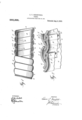
- FIG. 1 is a side elevation, partly in section, of a tube constructed in accordance with thisv invention
- Fig. 2 is an enlarged detail view, illustrating a portion of the t-ubing shown in Fig. 1.
- each of the tubes A is formed of a single metallic strip. Prior to the spiraling o eration, this strip is laterally curved, as, or instance, by means of coacting die-rolls of the general character of those illustrated in Patent No. 630,503,
- this lateral curvature is shown as comprising the convex portion a and thefconcave portion a.
- the strip so laterally curved is formed into successive spirals by means of a mandrel, a bending dieor other suitable apparatus, the edge of one spiral overlapping upon and interlocking with the edge of the next adjacent spiral.
- the inner tube B is similarly spiraled, both operations proceeding simultaneously.
- Said inner tube B is, like the outer tube A, formed of a single strip Bf, and-this, also like the strip above described, is given a lateral curvature, such, for instance, as that illustrated in the drawing.
- the strip B is provided with a concavity b, and, on either side of this, with a convexity Z2', b2.
- the edge of one spiral is caused to overlap upon the edge of the adjacent spiral a substantial distance, as clearly shown in Fig. 2.
- the same l may be pro-v vided, at the point at ywhich it is to be overlapped after being spiraled, with a groove b3, and in this may be placed a gasket b4, the same being fed or drawn forward as the strip B is fed or drawn forward for the spiraling operation, and said gasket being preferably slightly compressed as the spirals are formed in the process of constructing the inner tube.
- tubing constructed in accordance ⁇ there are, as willbe seen, no joints to be opened as the structure is flexed or bent. Normally the parts occupy the position and relation illustrated in the drawing. As the tubing is bent, however, there is no separation of the spirals, the overlaps (and in addition the resiliency of the material where this is utilized) permitting such bending While, however, maintaining the same wall-diameter whether the tubing be bent or straight.
- a convex portion the edges of adjacent spirals of said secondA tube overlapping and interlocking, the overlapping edges ot' the spirals of the second tube underlying-the convex 'portion' a spirally formed metallic strip curved laterally to provide a concave portion and on either side thereof a .convex portion, the edges of adjacent spirals of said second tube overlapping and interlocking, the overlapping edges of thespirals of the second tube' underlying the convex portion of the strip of the outer tube and the overlapping edges of the spirals of the outer tube overlying the concave portion of the strip of the inner tube, and a gasket between the overlapping edges of the strip of the inner tube, substantially as set forth.
Landscapes
- Engineering & Computer Science (AREA)
- General Engineering & Computer Science (AREA)
- Mechanical Engineering (AREA)
- Rigid Pipes And Flexible Pipes (AREA)
Description
E. T. GRBENPIELD.
TUBING.
APPLICATION PILED DBO. 29, 1905.
Patented Aug.2, 1910.
w/rNEssEs Q1 hem ElDWIN T. GEEENFI'LI), OF KIAIVIESHA, NEW YORK.
sfrafrns rarniair caricia.
TUBING.
#To all it-'may concern: i
- Be it knowny that I, EDWIN `GREEN- rIELD, a` citizen of the United States, residing at Kiamesha, in the county of Sullivan s and State of New York, have invented a certain4 new and useful Improvement in Tubing, ofwhich the following is a specication, The objecty of the present invention is'to produce a metallic tube c'a able of use either l Y spect the invention is designed as an improvement lupon certain existing types of tubingvin'which as the same are bent, as, -for.'instance, 4in passing the same around a corner in the operation of house-wiring, cer- -tain joints .are opened so that the enveloping material at these points is possessed of 425'less strength than are the other portions of the tubing. 'Thus, where the tubing is used for -inclosing electric conductors of the character used -inhouse-wiring, these, when the tubing is straivht, are protected commonly by a double thicknessof the material used. When the tubing is bent, however, and the joints between the successive spirals opened, the conductors are protected, at certain points, by but a single thickness of the maatl terial, this spannin the spirals which have been separated as t e tubing has been bent. In carryingrout the invention, I form in ect a tube-within a tube, the material used o'r-veach being in the form of a metallic 40 strip; `Each of these strips is preferably passed between coact-ing die-rolls and laterally curved, so that when the same are subsequently, by means of suitable winding, forcing or other apparatus, formed into successive'spirals, one of such spirals will overla and interlock with the next adjacent spiral. As this operation proceeds, what is Ipractically another tube, composed also of laterally-curved metallic strips, is formed within the tube rst named, and, also like the latter, the edge of one spiral overlappin the edge of the next adjacent spirals. In exing a tubeA so constructed, the spirals of the inner tube are moved relatively to each other, the spirals of the outer tube permitting this more by reason, preferably, of
` Specification of Letters '.Patent. Application led December 29, 1905. Serial No. 293,784.
Patented aug. a, raie.
their resiliency than by the bodily movement (i. e., one part sliding or moving along the surface of the adjacent part) which characterizes the movement of the spirals of the inner tube. The extent of overlap of the spirals of the inner 'tube is such as to permit an required degree of movement without a ecting the interlocking relation of theselspirals. j
A preferred form which the invention may take is illustrated in the drawings, in which- 1 Figure l is a side elevation, partly in section, of a tube constructed in accordance with thisv invention, and Fig. 2 is an enlarged detail view, illustrating a portion of the t-ubing shown in Fig. 1.
Referring to these drawings, it will be seen that each of the tubes A and is formed of a single metallic strip. Prior to the spiraling o eration, this strip is laterally curved, as, or instance, by means of coacting die-rolls of the general character of those illustrated in Patent No. 630,503,
granted to me August 8th, 1899. ln thel present instance, this lateral curvature is shown as comprising the convex portion a and thefconcave portion a. The strip so laterally curved is formed into successive spirals by means of a mandrel, a bending dieor other suitable apparatus, the edge of one spiral overlapping upon and interlocking with the edge of the next adjacent spiral. As this operation is performed, the inner tube B is similarly spiraled, both operations proceeding simultaneously. Said inner tube B is, like the outer tube A, formed of a single strip Bf, and-this, also like the strip above described, is given a lateral curvature, such, for instance, as that illustrated in the drawing. At about its longitudinal center, the strip B is provided with a concavity b, and, on either side of this, with a convexity Z2', b2. In winding, bending or otherwise forming the strip B to form the inner tube B, the edge of one spiral is caused to overlap upon the edge of the adjacent spiral a substantial distance, as clearly shown in Fig. 2. If desired, during the process of laterally curving the strip B', the same lmay be pro-v vided, at the point at ywhich it is to be overlapped after being spiraled, with a groove b3, and in this may be placed a gasket b4, the same being fed or drawn forward as the strip B is fed or drawn forward for the spiraling operation, and said gasket being preferably slightly compressed as the spirals are formed in the process of constructing the inner tube.
I prefer to so construct the spirals of the outer tube A that the same will oppose some resistance to bending, permitting such bending largely, if not chiefly, by reason of the resiliency of the metal of which such outer tube is composed. On the other hand, I also prefer to so construct the spirals of the inner tube that, the outer tube permitting, these spirals may be' moved relatively to each other, the engaging portions of the overlaps sliding or moving more or less readily upon each other. The structure so characterized is preferred for practical reasons. Also I prefer for various reasons, as, for instance, economy of space, that the overlaps of the inner tube B be arranged to alternate with the overlaps of the outer tube A, as clearly shown in the drawings.
In tubing constructed in accordance `,with this invention, there are, as willbe seen, no joints to be opened as the structure is flexed or bent. Normally the parts occupy the position and relation illustrated in the drawing. As the tubing is bent, however, there is no separation of the spirals, the overlaps (and in addition the resiliency of the material where this is utilized) permitting such bending While, however, maintaining the same wall-diameter whether the tubing be bent or straight.
Having now describedv my invention, what I claim as new therein and desire to secure by Letters Patent is as follows l. The combination of a. tube consisting of a spirally formed metallic strip curved laterally to provide al convex and a concave portion, the edges of adjacent spirals of said tube overlapping and interlocking, and a second tube inclosed Within said tube consisting of a spirally formed metallic strip curved laterally to rovide a concave portion and'on either si e thereof. a convex portion, the edges of adjacent spirals of said secondA tube overlapping and interlocking, the overlapping edges ot' the spirals of the second tube underlying-the convex 'portion' a spirally formed metallic strip curved laterally to provide a concave portion and on either side thereof a .convex portion, the edges of adjacent spirals of said second tube overlapping and interlocking, the overlapping edges of thespirals of the second tube' underlying the convex portion of the strip of the outer tube and the overlapping edges of the spirals of the outer tube overlying the concave portion of the strip of the inner tube, and a gasket between the overlapping edges of the strip of the inner tube, substantially as set forth.
This specilication signed and witnessed this 27th day of December, 1905.
EDWIN T. GREENFIELD.
l/Vitnesses: J. O.Y EDMONDS I. MoINTosH.
es of the spirals of the outer
Priority Applications (1)
| Application Number | Priority Date | Filing Date | Title |
|---|---|---|---|
| US29378405A US966396A (en) | 1905-12-29 | 1905-12-29 | Tubing. |
Applications Claiming Priority (1)
| Application Number | Priority Date | Filing Date | Title |
|---|---|---|---|
| US29378405A US966396A (en) | 1905-12-29 | 1905-12-29 | Tubing. |
Publications (1)
| Publication Number | Publication Date |
|---|---|
| US966396A true US966396A (en) | 1910-08-02 |
Family
ID=3034790
Family Applications (1)
| Application Number | Title | Priority Date | Filing Date |
|---|---|---|---|
| US29378405A Expired - Lifetime US966396A (en) | 1905-12-29 | 1905-12-29 | Tubing. |
Country Status (1)
| Country | Link |
|---|---|
| US (1) | US966396A (en) |
-
1905
- 1905-12-29 US US29378405A patent/US966396A/en not_active Expired - Lifetime
Similar Documents
| Publication | Publication Date | Title |
|---|---|---|
| US4490575A (en) | Flexible hose with external sheathed electrical conductor | |
| US4203476A (en) | Wire reinforced hose | |
| US4693324A (en) | Current-carrying flexible hose | |
| US4224463A (en) | Dual wire hose | |
| US1263340A (en) | Spiral sheet-metal pipe. | |
| NL7905179A (en) | METHOD FOR MANUFACTURING SCREW-WRAPPED TUBES AND TUBES MANUFACTURED THEREOF | |
| US3085596A (en) | Collapsible tubing | |
| US1179578A (en) | Flexible pipe. | |
| US1134119A (en) | Cable-armor. | |
| US839381A (en) | Tubing. | |
| US591092A (en) | Flexible metallic tube or conduit | |
| US246232A (en) | Jsheet-metal tube | |
| US1215365A (en) | Cable-armor. | |
| US1275279A (en) | Conduit or conductor. | |
| US630636A (en) | Protective casing for electric cables or wires. | |
| US998827A (en) | Flexible conduit. | |
| US2367643A (en) | Plastic conduit | |
| US851343A (en) | Building-sheet. | |
| US1906010A (en) | Pipe and method of making the same | |
| US630635A (en) | Protective casing for electric cables or wires. | |
| AT140151B (en) | Metal pipe for laying electrical cables. | |
| US534564A (en) | Water or gas pipe | |
| US1725088A (en) | Counduit | |
| US630599A (en) | Protective casing for electric cables or wires. | |
| US1179576A (en) | Flexible tubing. |