US9663262B2 - Cotton module unwrapping method and apparatus - Google Patents
Cotton module unwrapping method and apparatus Download PDFInfo
- Publication number
- US9663262B2 US9663262B2 US14/347,988 US201214347988A US9663262B2 US 9663262 B2 US9663262 B2 US 9663262B2 US 201214347988 A US201214347988 A US 201214347988A US 9663262 B2 US9663262 B2 US 9663262B2
- Authority
- US
- United States
- Prior art keywords
- wrapping
- conveyor
- cotton
- lift conveyor
- module
- Prior art date
- Legal status (The legal status is an assumption and is not a legal conclusion. Google has not performed a legal analysis and makes no representation as to the accuracy of the status listed.)
- Active, expires
Links
Images


Classifications
-
- B—PERFORMING OPERATIONS; TRANSPORTING
- B65—CONVEYING; PACKING; STORING; HANDLING THIN OR FILAMENTARY MATERIAL
- B65B—MACHINES, APPARATUS OR DEVICES FOR, OR METHODS OF, PACKAGING ARTICLES OR MATERIALS; UNPACKING
- B65B69/00—Unpacking of articles or materials, not otherwise provided for
- B65B69/0008—Opening and emptying bags
-
- B—PERFORMING OPERATIONS; TRANSPORTING
- B65—CONVEYING; PACKING; STORING; HANDLING THIN OR FILAMENTARY MATERIAL
- B65B—MACHINES, APPARATUS OR DEVICES FOR, OR METHODS OF, PACKAGING ARTICLES OR MATERIALS; UNPACKING
- B65B69/00—Unpacking of articles or materials, not otherwise provided for
-
- D—TEXTILES; PAPER
- D01—NATURAL OR MAN-MADE THREADS OR FIBRES; SPINNING
- D01G—PRELIMINARY TREATMENT OF FIBRES, e.g. FOR SPINNING
- D01G7/00—Breaking or opening fibre bales
Definitions
- This invention relates to a cotton module unwrapping method and apparatus.
- the invention particularly relates, but is not limited to, a method of, and apparatus for, unwrapping round modules, or cylindrical rolls, of cotton wrapped in plastics-sheeting (e.g. polyethylene sheeting).
- plastics-sheeting e.g. polyethylene sheeting
- cotton shall be used to include other natural fibres (e.g. wool and flax) or fibrous materials (e.g. tobacco leaf).
- a major limitation with the plastics-sheeting wrapping is that the wrapping is easily damaged and can become a contaminant if introduced to the ginning process.
- the present invention resides in a method of unwrapping a (preferably round) module of cotton (or other fibrous material) from a wrapping of at least one layer of (preferably plastics-) sheet material including the steps of:
- the method includes the further step of:
- the wrapping is engaged by a discharge apparatus on the support frame for delivery to a waste collection site.
- the wrapped round module is conveyed to a feed side of the lift conveyor with the central axis of the round module arranged substantially vertically, when the lift conveyor is in the second position.
- the released cotton falls into a heap or pile on the lift conveyor, and is discharged from a discharge side of the lift conveyor when the lift conveyor has returned to the second position (and is capable of receiving the next round module to be unwrapped).
- the present invention resides in an unwrapping machine for unwrapping at least one layer of (preferably plastics-) sheet material wrapping from a (preferably round) module of cotton (or other fibrous material), the machine including:
- a lift conveyor (or vertically-movable support surface), within the support frame;
- a lifting mechanism to selectively move the lift conveyor from a first (or raised) position to a second (or lowered) position
- the support mechanisms are mounted on the support frame and are operable to selectively advance the gripper heads into engagement with the layer(s) of the sheet material wrapping; so arranged that:
- the support mechanisms retract the gripper heads outwardly towards the support frame to cause the wrapping to be expanded to progressively release the cotton from the lower portion to the upper portion of the round module onto the lift conveyor.
- a feed conveyor delivers the unwrapped round modules to a feed side of the lift conveyor, when the lift conveyor is in the second position.
- a discharge conveyor receives the released cotton from a discharge side of the lift conveyor when the lift conveyor has returned to the second position.
- the feed and discharge sides are opposed on the lift conveyor.
- the lift conveyor has a carriage mounted on substantially-vertical guides on the support frame, the carriage supporting a conveyor belt or conveyor rollers to support the wrapped round module and the released cotton; and a drive mechanism for the conveyor belt or conveyor rollers.
- the lifting mechanism employs cables and sheaves, or chains and sprockets, or hydraulic- or pneumatic-ram(s), to raise and lower the lift conveyor.
- the support frame has a plurality of posts or columns, where each column supports a respective support mechanism.
- each support mechanism incorporates a scissor-arms assembly, or like arrangement, to selectively advance/retract their respective gripper heads in a substantially-vertical orientation.
- each gripper head has a substantially-vertical engagement face or plate, and a plurality of gripper fingers or spikes extend there-from to engage the wrapping.
- the fingers or spikes may be selectively retractable behind the engagement face or plate to release the wrapping.
- a discharge apparatus is provided at, or adjacent, the top of the support frame, and has at least one pair of pinch rollers adapted to engage an upper portion of the wrapping when at least a portion of the cotton has been released from the wrapping, together with a drive mechanism for the pinch rollers.
- the present invention resides in a gripper finger or spike for a gripper head for an unwrapping machine, the gripper finger or spike including:
- a chisel or knife-like cutting portion at the distal end of the shank, the cutting portion being locatable in a cutting position forwardly of the gripper head.
- the shank is mounted on a support rod in the gripper head and extends co-axially through a hole in an engagement face on the gripper head;
- the support rod is optionally mounted for movement between a retracted position, where the cutting portion is rearwardly of the engagement face, and the (extended) cutting position.
- FIG. 1 is a schematic top plan view of a first stage of the unwrapping method of the present invention
- FIG. 2 is a schematic side view of one method of orienting a round module with the feed conveyor
- FIG. 3 is a schematic end elevational view of a second method of orienting a round module with the feed conveyor
- FIG. 4 is a schematic top plan view of the second stage of the unwrapping method
- FIG. 5 is a schematic side view corresponding to FIG. 4 ;
- FIG. 6 is a schematic top plan view of the third stage of the unwrapping method
- FIG. 7 is a schematic side view corresponding to FIG. 6 ;
- FIG. 8 is a front isometric view of the unwrapping machine with the lift conveyor in a lowered position to receive the round module to be unwrapped;
- FIG. 9 is a similar view, with the lift conveyor in a raised position, where the round module is partially-unwrapped;
- FIG. 10 is a top plan view of the unwrapping machine after the commencement of the unwrapping operation
- FIG. 11 is a sectional side view taken on line Z-Z on FIG. 10 ;
- FIG. 12 is an enlarged side view of Detail A on FIG. 11 ;
- FIG. 13 is a similar view to FIG. 10 after the round module has been unwrapped
- FIG. 14 is a sectional side view taken on line Z-Z on FIG. 13 ;
- FIG. 15 is an enlarged side view of Detail A on FIG. 14 ;
- FIG. 16 is a front isometric view one of the scissor arm assemblies and associated gripper head of the machine
- FIG. 17 is a front elevational view of a first embodiment of the gripper head
- FIG. 18 is a side elevational view of the scissor arm assembly and gripper head, with a portion of the gripper head being shown in section on line A-A on FIG. 17 ;
- FIG. 19 is an enlarged side view of Detail B on FIG. 18 ;
- FIG. 20 is an underside front view of a second embodiment of the unwrapping machine.
- FIG. 21 is a top rear isometric view thereof
- FIG. 22 is a top plan view thereof
- FIG. 23 is a front elevational view thereof
- FIG. 24 is a rear sectional view thereof.
- FIG. 25 is a sectional side view of the unwrapping machine.
- FIGS. 1 to 3, 4 and 5, and 6 and 7 respectively, schematically illustrate the three primary stages of the method of unwrapping a round module 10 of cotton C, in accordance with the present invention.
- the wrapped round modules 10 are placed on a feed conveyor 20 , the round modules 10 being re-oriented, if necessary, so that the central axes of the round modules 10 are substantially vertical and (preferably) aligned with the center-line of the feed conveyor 20 .
- the wrapped round modules 10 are advanced into the unwrapping machine 30 sequentially, are raised to an unwrapping position by the lift conveyor 40 , and the wrapping W is engaged by the gripper heads 56 .
- the lift conveyor 40 is moved downwardly as the gripper heads 56 are retracted outwardly.
- the cotton C falls from the lower portion of the round module 10 onto the lift conveyor 40 .
- the conveyor belt 41 on the lift conveyor 40 is operated to advance the released cotton C onto the discharge conveyor 90 , which transports the pile of cotton C to the disperser conveyor 95 for further processing.
- the next wrapped round module 10 is advanced to the lift conveyor 40 , and the cycle is repeated.
- the controls for the feed conveyor 20 , the unwrapping machine 30 , and the discharge conveyor 90 will be linked e.g. by a computer-based system, so that the respective machines 20 , 30 , 90 operate in the desired operating sequence within the unwrapping cycle.
- the unwrapped round modules 10 may not be forwarded to the feed conveyor 20 with the desired orientation.
- the module transporter (not shown) can rotate the round module through 90° to the desired orientation.
- the module transporter places the round module 10 in a tipping cradle 21 , which is raised to deposit the round module 10 on the feed conveyor 20 with the desired orientation.
- the feed conveyor 20 may have a conveyor belt 22 to support/advance the round modules 10 to the unwrapping machine 30 .
- the feed conveyor 20 may have a plurality of driven rollers 23 , which allow any rubbish adhering to the exterior of the wrapping W to be dislodged and fall to the floor for collection, to minimize potential contamination of the released cotton C.
- the discharge conveyor 90 has a conveyor belt 91 to support the heap or pile of loose cotton C received from the lift conveyor and conveys the loose cotton C to the disperser conveyor 95 , where the cotton C passes through between substantially star-shaped rotor blades 96 mounted at equal spacing across horizontal drive-shafts 97 journalled in bearings in vertical side plates (not shown).
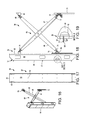
- the unwrapping machine 30 has a substantially square support frame 31 in top plan view—see FIG. 10 —with vertical columns 32 at respective corners of a base frame 33 anchored to the floor via corner foot-plates 34 and anchor bolts (not shown).
- the columns 32 connect the base frame 33 to a head frame 35 ; and the pairs of columns 32 , along the opposed sides of the path of the round modules 10 /released cotton C, are interconnected by cross-bars 36 and stabilised by angle braces 37 .
- the lift conveyor 40 has a carriage 42 , where parallel rollers (not shown) are journalled in bearings (not shown) in parallel side members 43 of a carriage chassis 44 , the rollers supporting the lift conveyor belt 41 , and the head and/or tail rollers are selectively driven by an electric- (or pneumatic-) motor (also not shown) to drive the lift conveyor belt 41 .
- the carriage chassis 44 of the lift conveyor 40 is guided in its vertical path between the lowered- and raised-positions by guide rollers (not shown) which engage vertical guide rails 45 which are mounted on the cross-bars 36 and the base frame 33 .
- a cable-and-pulley system 46 has respective head-pulleys 47 rotatably mounted on the intermediate cross-bars 36 and tail-pulleys 48 rotatably mounted on the base frame 33 .
- Each pair of head- and tail-pulleys 47 , 48 is provided with a lift cable 49 (as a continuous loop) to which is attached the carriage chassis 44 .
- One of the lift cables 49 is driven by the tail-pulley 48 connected to one end of a driveshaft 50 on a lift motor/transmission assembly 51 mounted on the base frame 33 .
- the other lift cable 49 is driven by a driving cable 52 which connects a driving pulley 53 , at the other end of the driveshaft 50 on the lift motor/transmission assembly 51 , to a driven pulley 54 on a driving shaft 55 to which the tail-pulley 48 is connected.
- the arrangement of the lift cables 49 ensures that both sides of the carriage chassis 44 are raised/lowered in unison.
- respective gripper heads 56 are mounted on each column 32 of the support frame via respective support mechanisms 64 , each incorporating a scissor-arms assembly 65 .
- Each gripper head 56 has a hollow body 57 with a substantially vertical engagement plate 58 connected to a backing plate 59 by side webs 60 .
- Gripper fingers or spikes 61 are mounted on support rods 62 behind the engagement plate 58 and extend through respective holes 63 in the engagement plate 58 .
- the support rods 62 may be fixed relative to the engagement plate 58 ; or may be horizontally-movable relatives thereto to enable the gripper fingers or spikes 61 to be retracted so as to not project from the engagement plate 58 on initial engagement with the round module 10 .
- the gripper fingers or spikes 61 have chisel or knife-like cutting edges 161 , rather than a pointed tip, to cleanly cut the wrapping W. (Conventional pointed spikes tend to rip a hole in the wrapping W, leaving a small piece of plastic stretched over the end of the spike. At some time, the spike releases the piece of plastic in the round module, to thereby inject contamination into the cotton in the round module.)
- the support mechanism 64 for each gripper head has a scissor-arms assembly 65 , with respective first- and second scissor arms 66 , 67 .
- the first scissor arm 66 has its outer (upper) end hingedly connected to the adjacent column 32 by a hinge assembly 68 .
- the inner (lower) end is hingedly connected to a first traveler 69 slidably mounted on a vertical guide track 70 on the backing plate 59 of the gripper head 56 , via a hinge assembly 71 .
- the second scissor arm 67 has its inner (upper) end hingedly connected to the backing plate 59 of the gripper head 56 ; and its lower (outer) end hingedly connected to a second traveler 72 slidably mounted on a vertical guide track 73 on the column 32 ; via similar hinge assemblies 74 , 75 .
- a pneumatic actuator (or ram) 76 has the lower end of a cylinder 77 mounted on the column 32 and the distal end of the piston rod 78 is connected to a bracket 79 at the lower end of the second traveler 72 .
- the pneumatic actuator 76 By extending the pneumatic actuator 76 , the scissor arms 66 , 67 move the gripper head 56 inwardly towards the centre of the unwrapping machine 30 i.e. away from the column 32 .
- the discharge mechanism 80 is mounted on the head frame 34 above the discharge end of the lift conveyor 40 .
- a pair of pinch rollers 81 has parallel rotational axes spring-mounted on the inwardly-directed portion of the body 82 of the discharge mechanism 80 , the pinch rollers 81 being driven by an electric unwrapping motor via a belt-and-pulley drive assembly 83 .
- a pair of compression rollers 84 are mounted rearwardly (i.e. outwardly) of the pinch rollers 81 and rotate about horizontal axes, the compression rollers 84 being driven by an electric compression drive motor.
- a lower bag guide roller 86 is mounted forwardly of, and below, the lower of the compression rollers 84 .
- the axle of at least the upper compression roller 84 is journalled in bearings which are vertically movable within the discharge mechanism body 82 and are vertically movable via a compression roller cylinder 87 ; so that the compression rollers 84 apply a preset minimum compressive force on the unwrapped plastic wrap W as it is drawn away from the cotton C by the pinch and compression rollers 81 , 84 .
- a bag pinch gripper 100 in the form of a hook 101 , is hingedly mounted on, and extends inwardly from, a pinch gripper head 102 which can be extended inwardly, or retracted outwardly, by a pneumatic pull back cylinder 103 ; the bag pinch gripper 100 being able to be swung downwardly into engagement with the adjacent portion of the wrapping W.
- a vertical wrap spindle 104 is mounted rearwardly (i.e. outwardly) of the compression rollers 84 to receive the waste wrapping W drawn from the round module 10 , and is driven by an electric wrap motor 105 .
- An RF plastics-welding head 106 with an extendible/retractable welding iron 107 , is located adjacent the wrap spindle 104 .
- a pneumatic eject cylinder 108 vertically moves the wrap spindle 104 from a (raised) wrapping position to a (lowered) discharge position, where a waste roll R comprising one or more wrapped/welded waste wrappings on the wrap spindle 104 is transferred to a transverse waste discharge conveyor 109 for transport to a waste discharge location.
- the waste discharge conveyor 109 is mounted on the head frame 34 of the unwrapping machine 30 and has a conveyor belt 110 to support and convey the waste rolls R.
- the lift conveyor 40 receives a round module 10 to be unwrapped from the feed conveyor 20 , in the correct orientation, as illustrated in FIGS. 4 and 5 , where the lift conveyor belt 41 advances the round module 10 to the centre of the carriage 42 .
- the lift motor/transmission assembly 51 is operated to drive the lift cables 49 to raise the carriage 42 to the raised position—see FIGS. 5 and 9 .
- the pneumatic actuators 76 for each support mechanism 64 is extended, to cause the scissor arms 66 , 67 to advance the gripper heads 56 towards the round module 10 until the engagement plates 58 engage the wrapping W, which is pierced by the gripper fingers or spikes 61 .
- the gripper fingers or spikes 61 are movably mounted in each gripper head 56 , it is preferable they are retracted as the engagement plates 58 engage the wrapping W, and are then extended into engagement with the wrapping W.
- the bag pinch gripper 100 is also extended and swung down to engage the upper rim of the wrapping W.
- the unwrapping step now commences.
- the gripper heads 56 and the bag pinch gripper 100 are simultaneously retracted (i.e. moved outwardly) by the pneumatic actuators 76 and the pneumatic pull back cylinder 103 , while the lift motor/transmission assembly 51 is operated to slowly lower the lift conveyor carriage 42 —see FIGS. 10 to 12 .
- the cotton C in the lower portion of the round module 10 is no longer supported by the lift conveyor belt 41 , and the four-way stretching of the wrapping W by the gripper heads 56 reduces the frictional contact between the cotton C in the round module 10 and the wrapping W.
- the cotton C in the lower portion starts falling free from the roll module 10 , and the cotton C is gradually released from the lower portion to the upper portion, until all the cotton C is received on, and supported by, the lift conveyor belt 41 in a heap or pile.
- the bag pinch gripper 100 As the bag pinch gripper 100 is retracted, it feeds the engaged portion of the upper rim of the wrapping W into engagement with the (driven) pinch rollers 81 (and over the lower bag guide roller 86 ) to the compression rollers 84 .
- the wrapping W is drawn away from the centre of the unwrapping machine 30 and is wound onto the vertical wrap spindle 104 .
- the RF welding head 106 advances the welding iron 107 , to weld the wrapping W into a waste roll R about the wrap spindle 104 .
- the eject cylinder 108 is extended to transfer the waste roll R to the waste discharge conveyor 109 for transfer to a waste discharge location.
- NB A number of the wrappings W may be formed into a waste roll Ron the wrap spindle 104 before transfer to the waste discharge conveyor 109 .
- waste rolls R can be returned to a plastics manufacturer for recycling of the plastics-material.
- the lift conveyor belt 41 is operated to transfer the cotton C to the discharge conveyor 90 —see FIGS. 6 and 7 .
- the lift conveyor 40 is ready to receive the next round module 10 to be unwrapped, and the cycle is repeated.
- FIGS. 20 to 25 illustrate a second embodiment of the unwrapping machine 230 where the bag pinch gripper 300 has a movable jaw 301 , moved by a pneumatic cylinder 302 , and co-operates with a fixed jaw, or anvil, 303 to grip the upper rim of the wrapping W, before the bag pinch gripper 300 is retracted by rams 376 to enable the wrapping to be received on the wrap spindle 304 .
- the wrap W gripped by the bag pinch gripper 300 is guided towards the compression rollers 384 by vertical head rollers 382 driven by belts 381 and over a lower guide belt passing around the guide roller 386 .
- the belts 381 will assist in guiding the wrap W towards the compression rollers 384 .
- the unwrapping method and apparatus 230 is arranged to direct the wrap W, in a single piece, to the wrapping spindle 304 to ensure none of the wrap W contaminates the cotton released from the module.
- the plastics-material is positively drawn away from the cotton, and is collected/transported for recycling;
- the unwrapping machine can be easily integrated with existing feed and discharge conveyors at the cotton gin;
- the feed conveyor, unwrapping machine and the discharge conveyor can be easily linked, and their respective operations timed/controlled by a master (programmable) control system;
- the unwrapping machine can be constructed from many off-the-shelf components, at a reduced capital, cost, while providing a robust/reliable machine;
- the present invention provides a relatively simple, but safe and highly efficient, method of, and apparatus for, the unwrapping of round modules of cotton or like materials.
Abstract
A method of, and apparatus for, unwrapping a module of cotton or other fibrous material from a wrapping having at least one layer of plastics-sheet material, the method including the steps of: raising the module to a first, or elevated, position on a lift conveyor or vertically-movable support surface; advancing a plurality of gripper heads, mounted on a support frame, to an advanced position, into gripping engagement with the layer(s) of the sheet material wrapping; lowering the lift conveyor or vertically-movable support surface from the first position towards a second, or lowered, position; and retracting the plurality of gripper heads, to expand the wrapping to progressively release the cotton or other fibrous material from the lower portion to the upper portion of the module.
Description
1. Field of the Invention
This invention relates to a cotton module unwrapping method and apparatus.
The invention particularly relates, but is not limited to, a method of, and apparatus for, unwrapping round modules, or cylindrical rolls, of cotton wrapped in plastics-sheeting (e.g. polyethylene sheeting).
Throughout the specification, the term “cotton” shall be used to include other natural fibres (e.g. wool and flax) or fibrous materials (e.g. tobacco leaf).
2. Prior Art
Conventionally, harvested cotton has been compressed into large rectangular modules for transport. These rectangular modules require large machines to form the rectangular modules in the field.
Due to the bulk and weight of the rectangular modules, large transport and handling systems are required to transport the rectangular modules to the cotton gin for processing of the cotton.
In recent years, there has been a transition to forming the harvested cotton in round modules (i.e. cylindrical rolls), which are wrapped in several layers of plastics-material (e.g. polyethylene) sheeting. Many cotton farmers are transitioning to round modules to reduce the amount of equipment and seasonal labour required to harvest the crop.
A major limitation with the plastics-sheeting wrapping is that the wrapping is easily damaged and can become a contaminant if introduced to the ginning process.
It is an object of the invention to provide a method for releasing the cotton in a round module, or cylindrical roll, from the surrounding wrapping where the likelihood of the wrapping contaminating the cotton is overcome, or at least ameliorated.
It is a preferred object of the present invention to provide such a method where the release of the cotton in the round module from the wrapping is controlled and conducted in a safe manner.
It is a further preferred object to provide a method where the released wrapping is drawn, or otherwise moved, away from the released cotton.
It is a still further preferred object to provide an unwrapping machine for affecting the unwrapping method.
Other preferred objects will become apparent from the following description.
In one aspect, the present invention resides in a method of unwrapping a (preferably round) module of cotton (or other fibrous material) from a wrapping of at least one layer of (preferably plastics-) sheet material including the steps of:
a) raising the round module to a first (or elevated) position on a lift conveyor (or vertically-movable support surface);
b) advancing a plurality of gripper heads, mounted on a support frame, to an advanced position, into gripping engagement with the layer(s) of the sheet material wrapping;
c) lowering the lift conveyor (or vertically-movable support surface) from the first position towards a second (or lowered) position; and
d) retracting the plurality of gripper heads, to expand the wrapping to progressively release the cotton (or other fibrous material) from the lower portion to the upper portion of the round module.
Preferably, the method includes the further step of:
e) as, or after, the lower portion of the cotton is being released from the wrapping, the wrapping is engaged by a discharge apparatus on the support frame for delivery to a waste collection site.
Preferably, the wrapped round module is conveyed to a feed side of the lift conveyor with the central axis of the round module arranged substantially vertically, when the lift conveyor is in the second position.
Preferably, the released cotton falls into a heap or pile on the lift conveyor, and is discharged from a discharge side of the lift conveyor when the lift conveyor has returned to the second position (and is capable of receiving the next round module to be unwrapped).
In a second aspect, the present invention resides in an unwrapping machine for unwrapping at least one layer of (preferably plastics-) sheet material wrapping from a (preferably round) module of cotton (or other fibrous material), the machine including:
a support frame;
a lift conveyor (or vertically-movable support surface), within the support frame;
a lifting mechanism to selectively move the lift conveyor from a first (or raised) position to a second (or lowered) position;
a plurality of gripper heads, the gripper heads being mounted on movable support mechanisms; and
the support mechanisms are mounted on the support frame and are operable to selectively advance the gripper heads into engagement with the layer(s) of the sheet material wrapping; so arranged that:
as the lifting mechanism lowers the lift conveyor from the first position to the second position, the support mechanisms retract the gripper heads outwardly towards the support frame to cause the wrapping to be expanded to progressively release the cotton from the lower portion to the upper portion of the round module onto the lift conveyor.
Preferably, a feed conveyor delivers the unwrapped round modules to a feed side of the lift conveyor, when the lift conveyor is in the second position.
Preferably, a discharge conveyor receives the released cotton from a discharge side of the lift conveyor when the lift conveyor has returned to the second position. Preferably, the feed and discharge sides are opposed on the lift conveyor.
Preferably, the lift conveyor has a carriage mounted on substantially-vertical guides on the support frame, the carriage supporting a conveyor belt or conveyor rollers to support the wrapped round module and the released cotton; and a drive mechanism for the conveyor belt or conveyor rollers.
Preferably, the lifting mechanism employs cables and sheaves, or chains and sprockets, or hydraulic- or pneumatic-ram(s), to raise and lower the lift conveyor.
Preferably, the support frame has a plurality of posts or columns, where each column supports a respective support mechanism.
Preferably, each support mechanism incorporates a scissor-arms assembly, or like arrangement, to selectively advance/retract their respective gripper heads in a substantially-vertical orientation.
Preferably, each gripper head has a substantially-vertical engagement face or plate, and a plurality of gripper fingers or spikes extend there-from to engage the wrapping. The fingers or spikes may be selectively retractable behind the engagement face or plate to release the wrapping.
Preferably, a discharge apparatus is provided at, or adjacent, the top of the support frame, and has at least one pair of pinch rollers adapted to engage an upper portion of the wrapping when at least a portion of the cotton has been released from the wrapping, together with a drive mechanism for the pinch rollers.
In a third aspect, the present invention resides in a gripper finger or spike for a gripper head for an unwrapping machine, the gripper finger or spike including:
a shank mountable on the gripper head at an inner end; and
a chisel or knife-like cutting portion at the distal end of the shank, the cutting portion being locatable in a cutting position forwardly of the gripper head.
Preferably, the shank is mounted on a support rod in the gripper head and extends co-axially through a hole in an engagement face on the gripper head; and
the support rod is optionally mounted for movement between a retracted position, where the cutting portion is rearwardly of the engagement face, and the (extended) cutting position.
To enable the invention to be fully understood, preferred embodiments will now be described with reference to the accompanying drawings, in which:
NB: Any annotations, dimensions, notes or other descriptive markings, on the drawings are for illustration purposes and to assist the skilled addressee in the understanding of the invention only, and are not limiting to the scope of invention.
In the first stage illustrated in FIGS. 1 to 3 , the wrapped round modules 10, e.g. as received from the field, are placed on a feed conveyor 20, the round modules 10 being re-oriented, if necessary, so that the central axes of the round modules 10 are substantially vertical and (preferably) aligned with the center-line of the feed conveyor 20.
In the second stage, illustrated in FIGS. 4 and 5 , the wrapped round modules 10 are advanced into the unwrapping machine 30 sequentially, are raised to an unwrapping position by the lift conveyor 40, and the wrapping W is engaged by the gripper heads 56.
In the third stage illustrated in FIGS. 6 and 7 , the lift conveyor 40 is moved downwardly as the gripper heads 56 are retracted outwardly. The cotton C falls from the lower portion of the round module 10 onto the lift conveyor 40. When the lift conveyor 40 is fully lowered, the conveyor belt 41 on the lift conveyor 40 is operated to advance the released cotton C onto the discharge conveyor 90, which transports the pile of cotton C to the disperser conveyor 95 for further processing.
The next wrapped round module 10 is advanced to the lift conveyor 40, and the cycle is repeated.
It will be appreciated by the skilled addressee that the controls for the feed conveyor 20, the unwrapping machine 30, and the discharge conveyor 90 will be linked e.g. by a computer-based system, so that the respective machines 20, 30, 90 operate in the desired operating sequence within the unwrapping cycle.
As illustrated in FIGS. 2 and 3 , the unwrapped round modules 10 may not be forwarded to the feed conveyor 20 with the desired orientation. In FIG. 2 , where the central axis of the round module 10 is substantially aligned with the longitudinal axis of the feed conveyor 20, but is “laid down” substantially horizontally, the module transporter (not shown) can rotate the round module through 90° to the desired orientation. Alternatively, in FIG. 3 , if the central axis of the wrapped round module 10 is transverse to the longitudinal axis of the feed conveyor 20, the module transporter places the round module 10 in a tipping cradle 21, which is raised to deposit the round module 10 on the feed conveyor 20 with the desired orientation.
The feed conveyor 20 may have a conveyor belt 22 to support/advance the round modules 10 to the unwrapping machine 30. Alternatively, the feed conveyor 20 may have a plurality of driven rollers 23, which allow any rubbish adhering to the exterior of the wrapping W to be dislodged and fall to the floor for collection, to minimize potential contamination of the released cotton C.
The discharge conveyor 90 has a conveyor belt 91 to support the heap or pile of loose cotton C received from the lift conveyor and conveys the loose cotton C to the disperser conveyor 95, where the cotton C passes through between substantially star-shaped rotor blades 96 mounted at equal spacing across horizontal drive-shafts 97 journalled in bearings in vertical side plates (not shown).
Referring to FIGS. 8 and 9 , the unwrapping machine 30 has a substantially square support frame 31 in top plan view—see FIG. 10 —with vertical columns 32 at respective corners of a base frame 33 anchored to the floor via corner foot-plates 34 and anchor bolts (not shown). The columns 32 connect the base frame 33 to a head frame 35; and the pairs of columns 32, along the opposed sides of the path of the round modules 10/released cotton C, are interconnected by cross-bars 36 and stabilised by angle braces 37.
The lift conveyor 40 has a carriage 42, where parallel rollers (not shown) are journalled in bearings (not shown) in parallel side members 43 of a carriage chassis 44, the rollers supporting the lift conveyor belt 41, and the head and/or tail rollers are selectively driven by an electric- (or pneumatic-) motor (also not shown) to drive the lift conveyor belt 41.
The carriage chassis 44 of the lift conveyor 40 is guided in its vertical path between the lowered- and raised-positions by guide rollers (not shown) which engage vertical guide rails 45 which are mounted on the cross-bars 36 and the base frame 33.
A cable-and-pulley system 46 has respective head-pulleys 47 rotatably mounted on the intermediate cross-bars 36 and tail-pulleys 48 rotatably mounted on the base frame 33. Each pair of head- and tail- pulleys 47, 48 is provided with a lift cable 49 (as a continuous loop) to which is attached the carriage chassis 44. One of the lift cables 49 is driven by the tail-pulley 48 connected to one end of a driveshaft 50 on a lift motor/transmission assembly 51 mounted on the base frame 33. The other lift cable 49 is driven by a driving cable 52 which connects a driving pulley 53, at the other end of the driveshaft 50 on the lift motor/transmission assembly 51, to a driven pulley 54 on a driving shaft 55 to which the tail-pulley 48 is connected. The arrangement of the lift cables 49 ensures that both sides of the carriage chassis 44 are raised/lowered in unison.
As illustrated in FIGS. 8 to 11, 13 to 14 , and in more detail in FIGS. 16 to 19 , respective gripper heads 56 are mounted on each column 32 of the support frame via respective support mechanisms 64, each incorporating a scissor-arms assembly 65.
Each gripper head 56 has a hollow body 57 with a substantially vertical engagement plate 58 connected to a backing plate 59 by side webs 60. Gripper fingers or spikes 61—see FIG. 19 —are mounted on support rods 62 behind the engagement plate 58 and extend through respective holes 63 in the engagement plate 58. (The support rods 62 may be fixed relative to the engagement plate 58; or may be horizontally-movable relatives thereto to enable the gripper fingers or spikes 61 to be retracted so as to not project from the engagement plate 58 on initial engagement with the round module 10.)
The gripper fingers or spikes 61 have chisel or knife-like cutting edges 161, rather than a pointed tip, to cleanly cut the wrapping W. (Conventional pointed spikes tend to rip a hole in the wrapping W, leaving a small piece of plastic stretched over the end of the spike. At some time, the spike releases the piece of plastic in the round module, to thereby inject contamination into the cotton in the round module.)
The support mechanism 64 for each gripper head has a scissor-arms assembly 65, with respective first- and second scissor arms 66, 67.
The first scissor arm 66 has its outer (upper) end hingedly connected to the adjacent column 32 by a hinge assembly 68. The inner (lower) end is hingedly connected to a first traveler 69 slidably mounted on a vertical guide track 70 on the backing plate 59 of the gripper head 56, via a hinge assembly 71.
The second scissor arm 67 has its inner (upper) end hingedly connected to the backing plate 59 of the gripper head 56; and its lower (outer) end hingedly connected to a second traveler 72 slidably mounted on a vertical guide track 73 on the column 32; via similar hinge assemblies 74, 75.
A pneumatic actuator (or ram) 76 has the lower end of a cylinder 77 mounted on the column 32 and the distal end of the piston rod 78 is connected to a bracket 79 at the lower end of the second traveler 72. By extending the pneumatic actuator 76, the scissor arms 66, 67 move the gripper head 56 inwardly towards the centre of the unwrapping machine 30 i.e. away from the column 32.
Referring to FIGS. 10 to 15 , the discharge mechanism 80 is mounted on the head frame 34 above the discharge end of the lift conveyor 40.
A pair of pinch rollers 81 has parallel rotational axes spring-mounted on the inwardly-directed portion of the body 82 of the discharge mechanism 80, the pinch rollers 81 being driven by an electric unwrapping motor via a belt-and-pulley drive assembly 83.
A pair of compression rollers 84 are mounted rearwardly (i.e. outwardly) of the pinch rollers 81 and rotate about horizontal axes, the compression rollers 84 being driven by an electric compression drive motor. A lower bag guide roller 86 is mounted forwardly of, and below, the lower of the compression rollers 84. The axle of at least the upper compression roller 84 is journalled in bearings which are vertically movable within the discharge mechanism body 82 and are vertically movable via a compression roller cylinder 87; so that the compression rollers 84 apply a preset minimum compressive force on the unwrapped plastic wrap W as it is drawn away from the cotton C by the pinch and compression rollers 81, 84.
A bag pinch gripper 100, in the form of a hook 101, is hingedly mounted on, and extends inwardly from, a pinch gripper head 102 which can be extended inwardly, or retracted outwardly, by a pneumatic pull back cylinder 103; the bag pinch gripper 100 being able to be swung downwardly into engagement with the adjacent portion of the wrapping W.
A vertical wrap spindle 104 is mounted rearwardly (i.e. outwardly) of the compression rollers 84 to receive the waste wrapping W drawn from the round module 10, and is driven by an electric wrap motor 105.
An RF plastics-welding head 106, with an extendible/retractable welding iron 107, is located adjacent the wrap spindle 104.
A pneumatic eject cylinder 108 vertically moves the wrap spindle 104 from a (raised) wrapping position to a (lowered) discharge position, where a waste roll R comprising one or more wrapped/welded waste wrappings on the wrap spindle 104 is transferred to a transverse waste discharge conveyor 109 for transport to a waste discharge location.
The waste discharge conveyor 109 is mounted on the head frame 34 of the unwrapping machine 30 and has a conveyor belt 110 to support and convey the waste rolls R.
The operational cycle of the unwrapping machine will now be described.
In the lowered position (see FIG. 8 ), the lift conveyor 40 receives a round module 10 to be unwrapped from the feed conveyor 20, in the correct orientation, as illustrated in FIGS. 4 and 5 , where the lift conveyor belt 41 advances the round module 10 to the centre of the carriage 42.
The lift motor/transmission assembly 51 is operated to drive the lift cables 49 to raise the carriage 42 to the raised position—see FIGS. 5 and 9 .
The pneumatic actuators 76 for each support mechanism 64 is extended, to cause the scissor arms 66, 67 to advance the gripper heads 56 towards the round module 10 until the engagement plates 58 engage the wrapping W, which is pierced by the gripper fingers or spikes 61. (When the gripper fingers or spikes 61 are movably mounted in each gripper head 56, it is preferable they are retracted as the engagement plates 58 engage the wrapping W, and are then extended into engagement with the wrapping W.)
The bag pinch gripper 100 is also extended and swung down to engage the upper rim of the wrapping W.
The unwrapping step now commences.
The gripper heads 56 and the bag pinch gripper 100 are simultaneously retracted (i.e. moved outwardly) by the pneumatic actuators 76 and the pneumatic pull back cylinder 103, while the lift motor/transmission assembly 51 is operated to slowly lower the lift conveyor carriage 42—see FIGS. 10 to 12 .
The cotton C in the lower portion of the round module 10 is no longer supported by the lift conveyor belt 41, and the four-way stretching of the wrapping W by the gripper heads 56 reduces the frictional contact between the cotton C in the round module 10 and the wrapping W.
The cotton C in the lower portion starts falling free from the roll module 10, and the cotton C is gradually released from the lower portion to the upper portion, until all the cotton C is received on, and supported by, the lift conveyor belt 41 in a heap or pile.
As the bag pinch gripper 100 is retracted, it feeds the engaged portion of the upper rim of the wrapping W into engagement with the (driven) pinch rollers 81 (and over the lower bag guide roller 86) to the compression rollers 84. The wrapping W is drawn away from the centre of the unwrapping machine 30 and is wound onto the vertical wrap spindle 104.
When the entire wrapping W is received on the wrap spindle 104, the RF welding head 106, advances the welding iron 107, to weld the wrapping W into a waste roll R about the wrap spindle 104.
The eject cylinder 108 is extended to transfer the waste roll R to the waste discharge conveyor 109 for transfer to a waste discharge location. (NB: A number of the wrappings W may be formed into a waste roll Ron the wrap spindle 104 before transfer to the waste discharge conveyor 109.)
The skilled addressee will appreciate the waste rolls R can be returned to a plastics manufacturer for recycling of the plastics-material.
When the lift conveyor carriage 42 is in the lowered position, supporting the heap or pile of released cotton C, the lift conveyor belt 41 is operated to transfer the cotton C to the discharge conveyor 90—see FIGS. 6 and 7 .
The lift conveyor 40 is ready to receive the next round module 10 to be unwrapped, and the cycle is repeated.
The wrap W gripped by the bag pinch gripper 300 is guided towards the compression rollers 384 by vertical head rollers 382 driven by belts 381 and over a lower guide belt passing around the guide roller 386. The belts 381 will assist in guiding the wrap W towards the compression rollers 384.
The unwrapping method and apparatus 230 is arranged to direct the wrap W, in a single piece, to the wrapping spindle 304 to ensure none of the wrap W contaminates the cotton released from the module.
The skilled addressee will appreciate the following (but non-exhaustive) list of advantages of the present invention include:
a) the cotton is released from the round modules in a controlled manner;
b) by not cutting the wrapping, the problem of waste plastics contaminating the released cotton is overcome, or at least ameliorated;
c) the plastics-material is positively drawn away from the cotton, and is collected/transported for recycling;
d) the unwrapping machine can be easily integrated with existing feed and discharge conveyors at the cotton gin;
e) the feed conveyor, unwrapping machine and the discharge conveyor can be easily linked, and their respective operations timed/controlled by a master (programmable) control system;
f) the unwrapping machine can be constructed from many off-the-shelf components, at a reduced capital, cost, while providing a robust/reliable machine;
g) the cotton is released into a heap or pile which is easily handled/transported; and
h) the system is fully automated and does not require a dedicated operator.
The present invention, as hereinbefore described and illustrated, provides a relatively simple, but safe and highly efficient, method of, and apparatus for, the unwrapping of round modules of cotton or like materials.
Various changes and modifications may be made to the embodiments described and illustrated without departing from the present invention.
Claims (10)
1. A method of unwrapping a module of cotton or other fibrous material from a wrapping of at least one layer of sheet material including the steps of:
a) raising the round module to a first, or elevated, position on a lift conveyor or vertically-movable support surface;
b) advancing a plurality of gripper heads, mounted on a support frame, to an advanced position, into gripping engagement with the layer(s) of the sheet material wrapping;
c) lowering the lift conveyor or vertically-movable support surface from the first position towards a second, or lowered, position; and
d) retracting the plurality of gripper heads, to expand the wrapping to progressively release the cotton or other fibrous material from the lower portion to the upper portion of the module.
2. The method of claim 1 , including the further step of:
e) as, or after, the lower portion of the cotton is being released from the wrapping, the wrapping is engaged by a discharge apparatus on the support frame for delivery to a waste collection site.
3. The method of claim 1 , including the further step:
before step a), the wrapped round module is conveyed to a feed side of the lift conveyor with the central axis of the module arranged substantially vertically, when the lift conveyor is in the second position.
4. The method of claim 3 , including the further step:
f) the released cotton falls into a heap or pile on the lift conveyor, and is discharged from a discharge side of the lift conveyor when the lift conveyor has returned to the second position.
5. An unwrapping machine for unwrapping at least one layer of sheet material wrapping from a module of cotton or other fibrous material, the machine including:
a support frame;
a lift conveyor or vertically-movable support surface, within the support frame;
a lifting mechanism to selectively move the lift conveyor from a first, or elevated, position to a second, or lowered, position;
a plurality of gripper heads, the gripper heads being mounted on movable support mechanisms; and
the support mechanisms are mounted on the support frame and are operable to selectively advance the gripper heads into engagement with the layer(s) of the sheet material wrapping; so arranged that:
as the lifting mechanism lowers the lift conveyor from the first position to the second position, the support mechanisms retract the gripper heads outwardly towards the support frame to cause the wrapping to be expanded to progressively release the cotton from the lower portion to the upper portion of the module onto the lift conveyor.
6. The machine of claim 5 , wherein:
a feed conveyor delivers the unwrapped modules to a feed side of the lift conveyor, when the lift conveyor is in the second position; and
a discharge conveyor receives the released cotton from a discharge side of the lift conveyor when the lift conveyor has returned to the second position; the feed and discharge sides being on opposed sides of the lift conveyor.
7. The machine of claim 5 , wherein:
the lift conveyor has a carriage mounted on substantially-vertical guides on the support frame, the carriage supporting a conveyor belt or conveyor rollers to support the wrapped module and the released cotton; and a drive mechanism for the conveyor belt or conveyor rollers; and
the lifting mechanism employs cables and sheaves, or chains and sprockets, or hydraulic- or pneumatic-ram(s), to raise and lower the lift conveyor.
8. The machine of claim 5 , wherein:
the support frame has a plurality of posts or columns, where each column supports a respective support mechanism;
each support mechanism incorporates a scissor-arms assembly, or like arrangement, to selectively advance/retract their respective gripper heads in a substantially-vertical orientation; and,
each gripper head has a substantially-vertical engagement face or plate, and a plurality of gripper fingers extend there-from to engage the wrapping, the gripper fingers being selectively retractable behind the engagement place to release the wrapping.
9. The machine of claim 5 , further including:
a discharge apparatus is provided at, or adjacent, the top of the support frame, and has at least one pair of pinch rollers adapted to engage an upper portion of the wrapping when at least a portion of the cotton has been released from the wrapping, together with a drive mechanism for the pinch rollers.
10. A module of cotton or other fibrous material unwrapped by the method of claim 1 .
Applications Claiming Priority (3)
| Application Number | Priority Date | Filing Date | Title |
|---|---|---|---|
| AU2011904038A AU2011904038A0 (en) | 2011-09-30 | Cotton module unwrapping method and apparatus | |
| AU2011904038 | 2011-09-30 | ||
| PCT/AU2012/001194 WO2013044326A2 (en) | 2011-09-30 | 2012-09-28 | Cotton module unwrapping method and apparatus |
Publications (2)
| Publication Number | Publication Date |
|---|---|
| US20140363262A1 US20140363262A1 (en) | 2014-12-11 |
| US9663262B2 true US9663262B2 (en) | 2017-05-30 |
Family
ID=47996528
Family Applications (1)
| Application Number | Title | Priority Date | Filing Date |
|---|---|---|---|
| US14/347,988 Active 2032-10-18 US9663262B2 (en) | 2011-09-30 | 2012-09-28 | Cotton module unwrapping method and apparatus |
Country Status (3)
| Country | Link |
|---|---|
| US (1) | US9663262B2 (en) |
| AU (1) | AU2012315499B2 (en) |
| WO (1) | WO2013044326A2 (en) |
Families Citing this family (1)
| Publication number | Priority date | Publication date | Assignee | Title |
|---|---|---|---|---|
| US10900184B1 (en) * | 2013-02-08 | 2021-01-26 | Eric Prochnow | Distribution of deicing and anti-icing agents |
Citations (14)
| Publication number | Priority date | Publication date | Assignee | Title |
|---|---|---|---|---|
| US4466767A (en) * | 1981-03-10 | 1984-08-21 | Wully S.A. | Automatic apparatus for the positioning and removal of the casing of paper board boxes |
| US4548539A (en) * | 1982-12-23 | 1985-10-22 | The Japan Tobacco & Salt Public Corporation | Method and apparatus for unpacking a box packed with compressed material |
| US4681507A (en) * | 1983-10-12 | 1987-07-21 | Fleetwood Systems, Inc. | Method of automatically de-bagging can ends and like articles |
| US4680850A (en) * | 1985-02-26 | 1987-07-21 | Firma G.B. Boucherie | Process for removing the wrapper from a fibre bundle |
| US4929141A (en) * | 1989-02-21 | 1990-05-29 | International Baler Corp. | Bale-opening method and apparatus |
| US4988255A (en) * | 1989-02-22 | 1991-01-29 | The Upjohn Company | Unpackaging machine |
| US5148651A (en) * | 1991-01-30 | 1992-09-22 | Oji Seitai Kaisha, Ltd. | Unwrapping apparatus with swing arms and grippers |
| US5318399A (en) * | 1991-02-20 | 1994-06-07 | Trutzschler Gmbh & Co. Kg | Method and apparatus for removing ties and wrappers from textile fiber bales |
| US5371938A (en) * | 1992-12-24 | 1994-12-13 | Comas S.P.A. | Machine for cutting and removing the wrapper of a bale |
| WO1996028352A1 (en) | 1995-03-10 | 1996-09-19 | Bala Press Ab | A method and a device for opening and emptying a cover of plastic film and/or net |
| US7165928B2 (en) * | 2004-03-18 | 2007-01-23 | Deere & Company | Seed cotton handling system |
| US20090202327A1 (en) * | 2008-02-12 | 2009-08-13 | Cherokee Fabrication Co., Inc. | Cylindrical module unwrapping device and method |
| US20110194918A1 (en) * | 2009-11-08 | 2011-08-11 | John Freeman | Apparatus and Method for Removing Wrap from Cotton Modules |
| US20120219392A1 (en) * | 2009-08-17 | 2012-08-30 | Namoi Cotton Co-Operative Ltd | Method and assembly for processing round seed cotton modules |
Family Cites Families (1)
| Publication number | Priority date | Publication date | Assignee | Title |
|---|---|---|---|---|
| US5725349A (en) * | 1996-03-26 | 1998-03-10 | Garvey Corporation | Method and apparatus for removing shrinkwrap from a package of bottles |
-
2012
- 2012-09-28 AU AU2012315499A patent/AU2012315499B2/en active Active
- 2012-09-28 US US14/347,988 patent/US9663262B2/en active Active
- 2012-09-28 WO PCT/AU2012/001194 patent/WO2013044326A2/en active Application Filing
Patent Citations (14)
| Publication number | Priority date | Publication date | Assignee | Title |
|---|---|---|---|---|
| US4466767A (en) * | 1981-03-10 | 1984-08-21 | Wully S.A. | Automatic apparatus for the positioning and removal of the casing of paper board boxes |
| US4548539A (en) * | 1982-12-23 | 1985-10-22 | The Japan Tobacco & Salt Public Corporation | Method and apparatus for unpacking a box packed with compressed material |
| US4681507A (en) * | 1983-10-12 | 1987-07-21 | Fleetwood Systems, Inc. | Method of automatically de-bagging can ends and like articles |
| US4680850A (en) * | 1985-02-26 | 1987-07-21 | Firma G.B. Boucherie | Process for removing the wrapper from a fibre bundle |
| US4929141A (en) * | 1989-02-21 | 1990-05-29 | International Baler Corp. | Bale-opening method and apparatus |
| US4988255A (en) * | 1989-02-22 | 1991-01-29 | The Upjohn Company | Unpackaging machine |
| US5148651A (en) * | 1991-01-30 | 1992-09-22 | Oji Seitai Kaisha, Ltd. | Unwrapping apparatus with swing arms and grippers |
| US5318399A (en) * | 1991-02-20 | 1994-06-07 | Trutzschler Gmbh & Co. Kg | Method and apparatus for removing ties and wrappers from textile fiber bales |
| US5371938A (en) * | 1992-12-24 | 1994-12-13 | Comas S.P.A. | Machine for cutting and removing the wrapper of a bale |
| WO1996028352A1 (en) | 1995-03-10 | 1996-09-19 | Bala Press Ab | A method and a device for opening and emptying a cover of plastic film and/or net |
| US7165928B2 (en) * | 2004-03-18 | 2007-01-23 | Deere & Company | Seed cotton handling system |
| US20090202327A1 (en) * | 2008-02-12 | 2009-08-13 | Cherokee Fabrication Co., Inc. | Cylindrical module unwrapping device and method |
| US20120219392A1 (en) * | 2009-08-17 | 2012-08-30 | Namoi Cotton Co-Operative Ltd | Method and assembly for processing round seed cotton modules |
| US20110194918A1 (en) * | 2009-11-08 | 2011-08-11 | John Freeman | Apparatus and Method for Removing Wrap from Cotton Modules |
Non-Patent Citations (2)
| Title |
|---|
| International Search Report-Dec. 9, 2012. |
| International Search Report—Dec. 9, 2012. |
Also Published As
| Publication number | Publication date |
|---|---|
| WO2013044326A2 (en) | 2013-04-04 |
| WO2013044326A3 (en) | 2014-09-25 |
| AU2012315499B2 (en) | 2014-08-28 |
| AU2012315499A1 (en) | 2013-05-02 |
| US20140363262A1 (en) | 2014-12-11 |
Similar Documents
| Publication | Publication Date | Title |
|---|---|---|
| US10647463B2 (en) | Bale processor and binding remover | |
| CN111847009B (en) | Automatic unloading and feeding system and unloading and feeding method | |
| US20090202327A1 (en) | Cylindrical module unwrapping device and method | |
| DE60004378T2 (en) | PACKAGING METHOD AND DEVICE | |
| US9617021B2 (en) | Apparatus for bagging a bale and method of bagging such bale | |
| US9580194B2 (en) | Wrapping machine | |
| US8769801B2 (en) | Biomass bale processing system with automatic binding remover | |
| US9550597B2 (en) | Wrapping material removal method | |
| CN207329025U (en) | A kind of fully automatic high-speed destacking bale breaker | |
| US7757353B2 (en) | Digesting cylindrical modules | |
| CN111409904A (en) | Packaging bag supply, taking and opening equipment and method thereof | |
| US8091816B2 (en) | Round cotton module opener | |
| US9663262B2 (en) | Cotton module unwrapping method and apparatus | |
| CN108328361A (en) | Bag cargo automatic loading device | |
| JPS59187522A (en) | Device for automatically manufacturing mineral fiber roll unit | |
| CN107127742B (en) | Steel cable robot system for carrying original tobacco packages in woven fabric bag | |
| US20120219392A1 (en) | Method and assembly for processing round seed cotton modules | |
| CN206984491U (en) | A kind of high-order stacking winding machine equipment | |
| US20160031579A1 (en) | Net wrap and twine removal system and methods | |
| JP5005560B2 (en) | Corn field stump processing equipment | |
| CN115140350B (en) | Full-automatic foam case packer | |
| JP3004916B2 (en) | Dry noodle cutting device | |
| CN111702908B (en) | Miscellaneous tree recycling machine | |
| CN207158225U (en) | A kind of mineral wool palletizing apparatus | |
| JPH06183541A (en) | Sorter for tube unit |
Legal Events
| Date | Code | Title | Description |
|---|---|---|---|
| AS | Assignment |
Owner name: QUEENSLAND COTTON CORPORATION PTY LTD, AUSTRALIA Free format text: ASSIGNMENT OF ASSIGNORS INTEREST;ASSIGNORS:IRONS, BOBBY R;BALLENTINE, JEFF;MACNELLIE, STEVEN RONALD;SIGNING DATES FROM 20140715 TO 20140804;REEL/FRAME:033552/0822 |
|
| STCF | Information on status: patent grant |
Free format text: PATENTED CASE |
|
| MAFP | Maintenance fee payment |
Free format text: PAYMENT OF MAINTENANCE FEE, 4TH YEAR, LARGE ENTITY (ORIGINAL EVENT CODE: M1551); ENTITY STATUS OF PATENT OWNER: LARGE ENTITY Year of fee payment: 4 |