US9659590B1 - Angled near-field transducer and waveguide - Google Patents

Angled near-field transducer and waveguide Download PDF

Info

Publication number
US9659590B1
US9659590B1 US14/928,611 US201514928611A US9659590B1 US 9659590 B1 US9659590 B1 US 9659590B1 US 201514928611 A US201514928611 A US 201514928611A US 9659590 B1 US9659590 B1 US 9659590B1
Authority
US
United States
Prior art keywords
waveguide
output end
media
cross
energy
Prior art date
Legal status (The legal status is an assumption and is not a legal conclusion. Google has not performed a legal analysis and makes no representation as to the accuracy of the status listed.)
Expired - Fee Related
Application number
US14/928,611
Other versions
US20170125048A1 (en
Inventor
Chubing Peng
Current Assignee (The listed assignees may be inaccurate. Google has not performed a legal analysis and makes no representation or warranty as to the accuracy of the list.)
Seagate Technology LLC
Original Assignee
Seagate Technology LLC
Priority date (The priority date is an assumption and is not a legal conclusion. Google has not performed a legal analysis and makes no representation as to the accuracy of the date listed.)
Filing date
Publication date
Application filed by Seagate Technology LLC filed Critical Seagate Technology LLC
Priority to US14/928,611 priority Critical patent/US9659590B1/en
Assigned to SEAGATE TECHNOLOGY LLC reassignment SEAGATE TECHNOLOGY LLC ASSIGNMENT OF ASSIGNORS INTEREST (SEE DOCUMENT FOR DETAILS). Assignors: PENG, CHUBING
Publication of US20170125048A1 publication Critical patent/US20170125048A1/en
Application granted granted Critical
Publication of US9659590B1 publication Critical patent/US9659590B1/en
Expired - Fee Related legal-status Critical Current
Anticipated expiration legal-status Critical

Links

Images

Classifications

    • GPHYSICS
    • G11INFORMATION STORAGE
    • G11BINFORMATION STORAGE BASED ON RELATIVE MOVEMENT BETWEEN RECORD CARRIER AND TRANSDUCER
    • G11B5/00Recording by magnetisation or demagnetisation of a record carrier; Reproducing by magnetic means; Record carriers therefor
    • G11B5/127Structure or manufacture of heads, e.g. inductive
    • G11B5/31Structure or manufacture of heads, e.g. inductive using thin films
    • G11B5/3109Details
    • G11B5/313Disposition of layers
    • G11B5/3133Disposition of layers including layers not usually being a part of the electromagnetic transducer structure and providing additional features, e.g. for improving heat radiation, reduction of power dissipation, adaptations for measurement or indication of gap depth or other properties of the structure
    • G11B5/314Disposition of layers including layers not usually being a part of the electromagnetic transducer structure and providing additional features, e.g. for improving heat radiation, reduction of power dissipation, adaptations for measurement or indication of gap depth or other properties of the structure where the layers are extra layers normally not provided in the transducing structure, e.g. optical layers
    • GPHYSICS
    • G11INFORMATION STORAGE
    • G11BINFORMATION STORAGE BASED ON RELATIVE MOVEMENT BETWEEN RECORD CARRIER AND TRANSDUCER
    • G11B5/00Recording by magnetisation or demagnetisation of a record carrier; Reproducing by magnetic means; Record carriers therefor
    • G11B5/48Disposition or mounting of heads or head supports relative to record carriers ; arrangements of heads, e.g. for scanning the record carrier to increase the relative speed
    • G11B5/4806Disposition or mounting of heads or head supports relative to record carriers ; arrangements of heads, e.g. for scanning the record carrier to increase the relative speed specially adapted for disk drive assemblies, e.g. assembly prior to operation, hard or flexible disk drives
    • G11B5/4866Disposition or mounting of heads or head supports relative to record carriers ; arrangements of heads, e.g. for scanning the record carrier to increase the relative speed specially adapted for disk drive assemblies, e.g. assembly prior to operation, hard or flexible disk drives the arm comprising an optical waveguide, e.g. for thermally-assisted recording
    • GPHYSICS
    • G11INFORMATION STORAGE
    • G11BINFORMATION STORAGE BASED ON RELATIVE MOVEMENT BETWEEN RECORD CARRIER AND TRANSDUCER
    • G11B5/00Recording by magnetisation or demagnetisation of a record carrier; Reproducing by magnetic means; Record carriers therefor
    • G11B5/10Structure or manufacture of housings or shields for heads
    • G11B5/105Mounting of head within housing or assembling of head and housing
    • GPHYSICS
    • G11INFORMATION STORAGE
    • G11BINFORMATION STORAGE BASED ON RELATIVE MOVEMENT BETWEEN RECORD CARRIER AND TRANSDUCER
    • G11B5/00Recording by magnetisation or demagnetisation of a record carrier; Reproducing by magnetic means; Record carriers therefor
    • G11B5/48Disposition or mounting of heads or head supports relative to record carriers ; arrangements of heads, e.g. for scanning the record carrier to increase the relative speed
    • G11B5/58Disposition or mounting of heads or head supports relative to record carriers ; arrangements of heads, e.g. for scanning the record carrier to increase the relative speed with provision for moving the head for the purpose of maintaining alignment of the head relative to the record carrier during transducing operation, e.g. to compensate for surface irregularities of the latter or for track following
    • G11B5/60Fluid-dynamic spacing of heads from record-carriers
    • G11B5/6005Specially adapted for spacing from a rotating disc using a fluid cushion
    • G11B5/6088Optical waveguide in or on flying head
    • GPHYSICS
    • G11INFORMATION STORAGE
    • G11BINFORMATION STORAGE BASED ON RELATIVE MOVEMENT BETWEEN RECORD CARRIER AND TRANSDUCER
    • G11B5/00Recording by magnetisation or demagnetisation of a record carrier; Reproducing by magnetic means; Record carriers therefor
    • G11B2005/0002Special dispositions or recording techniques
    • G11B2005/0005Arrangements, methods or circuits
    • G11B2005/0021Thermally assisted recording using an auxiliary energy source for heating the recording layer locally to assist the magnetization reversal

Definitions

  • An apparatus comprises a waveguide and a near-field transducer.
  • the waveguide has an input end that receives energy in a transverse electric (TE 00 ) mode from an energy source along a substrate-parallel plane.
  • the near-field transducer is located proximate an output end of the waveguide and receives the energy in the TE 00 mode.
  • the output end of the waveguide is at an oblique angle to a cross-track line at an intersection of a media-facing surface and the substrate-parallel plane.
  • the near-field transducer comprises an enlarged portion comprising first and second curved ends connected by straight sides and is oriented at the oblique angle to the cross-track line. The peg extends from the enlarged portion towards the media-facing surface at a normal angle to the cross-track line.
  • An apparatus comprises a waveguide and a near-field transducer.
  • the waveguide has an input end that receives energy in a transverse electric (TE 00 ) mode from an energy source along a substrate-parallel plane and an output end, wherein a width of the waveguide in a cross-track direction varies between the input end and the output end.
  • the near-field transducer is located proximate an output end of the waveguide and receives the energy in the TE 00 mode.
  • the output end of the waveguide is at an oblique angle to a cross-track line at an intersection of a media-facing surface and the substrate-parallel plane.
  • the near-field transducer comprises an enlarged portion comprising first and second curved ends connected by straight sides and is oriented at the oblique angle to the cross-track line.
  • the peg extends from the enlarged portion towards the media-facing surface at a normal angle to the cross-track line.
  • a further embodiment is directed to a method comprising emitting energy in a transverse electric (TE 00 ) mode from an energy source to an input surface of a recording head.
  • the energy in the TE 00 mode is received with an input end of a waveguide proximate the input surface.
  • the energy in the TE 00 mode is guided to an output end of the waveguide proximate an output surface of the recording head.
  • the output end is at an oblique angle to a cross-track line at an intersection of the output surface and a plane normal to the output surface.
  • the energy is also guided to a near field transducer proximate the output end, wherein the near field transducer comprises an enlarged portion and a peg.
  • the enlarged portion comprises first and second circular ends connected by straight sides and oriented at the oblique angle to the cross-track line.
  • the energy is delivered to heat a portion of a recording medium via the near field transducer.
  • FIG. 1 is a perspective view of a slider assembly according to an example embodiment
  • FIGS. 2A-B are cross-sectional views illustrating waveguide configurations according to example embodiments
  • FIG. 3 is a graph illustrating reflected energy as a function of waveguide tilt angle according to example embodiments
  • FIG. 4A is a cross-sectional view in the cross-track direction of an angled waveguide with a near field transducer according to an example embodiment
  • FIG. 4B is a cross-sectional view in the down-track direction of the angled waveguide of FIG. 4A ;
  • FIG. 5 is a graph illustrating near-field transducer efficiency as a function of the length of the near-field transducer according to an example embodiment
  • FIG. 6 is a graph illustrating near-field transducer efficiency as a function of the peg height according to an example embodiment
  • FIG. 7A is an amplitude profile for TE 00 mode excitation
  • FIG. 7B is an amplitude profile for TE 10 mode excitation
  • FIGS. 8A-B are cross-sectional views of shaped waveguides according to example embodiments.
  • FIG. 9 is a graph illustrating near-field transducer efficiency as a function of type and length of waveguide shaping according to example embodiments.
  • FIG. 10A is a profile of light absorption by a recording medium for TE 00 mode excited energy according to an example embodiment
  • FIG. 10B is a profile of light absorption by a recording medium for TE 10 mode excited energy.
  • FIG. 11 is a flowchart illustrating a method according to an example embodiment.
  • the present disclosure is generally related to the use of an angled waveguide (e.g., channel waveguide) that receives light from an energy source (e.g., laser diode) and delivers the light to a recording medium (e.g., a thermally-assisted, magnetic recording medium) at an angle other than normal to the output surface of a recording head.
  • the waveguide is formed integrally within the recording head and additional recording head features (e.g., a near-field transducer) may also be formed at an angle.
  • the laser diode may be attached to an outer surface of the recording head and direct its output to the waveguide at an angle approximately normal to the output surface of the recording head.
  • the angle of the waveguide is selected to reduce reflection of the laser output from a recording medium and/or near-field transducer back to the laser diode. This reduction in reflection helps reduce laser instability issues including mode hopping.
  • a heat-assisted, magnetic recording (HAMR) data storage medium has a high magnetic coercivity that is able to overcome superparamagnetic effects (e.g., thermally-induced, random, changes in magnetic orientations) that currently limit the areal data density of conventional hard drive media.
  • superparamagnetic effects e.g., thermally-induced, random, changes in magnetic orientations
  • a small portion, or “hot spot,” of the magnetic medium is locally heated to its Curie temperature, thereby allowing magnetic orientation of the medium to be changed at the hot spot while being written to by a transducer (e.g., magnetic write pole). After the heat is removed, the region will maintain its magnetic state, thereby reliably storing the data for later retrieval.
  • a HAMR read/write element sometimes referred to as a slider or read/write head, includes magnetic read and write transducers similar to those on current hard drives. For example, data may be read by a magnetoresistive sensor that detects magnetic fluctuations of the moving medium. Data may be written to the magnetic medium by a write coil that is magnetically coupled to a write pole.
  • a HAMR slider will also generally include a source of energy, such as a laser diode, and an optical delivery path through the slider that delivers the energy to the surface of the medium.
  • the optical delivery path of a HAMR slider may include a near-field transducer (NFT) proximate a media-facing surface (e.g., air-bearing surface, contact surface).
  • NFT near-field transducer
  • the NFT shapes and transmits the energy to a small region on the medium.
  • the NFT is sometimes referred to as an optical antenna, surface plasmon resonator, etc.
  • the NFT for a HAMR device is very small (e.g., on the order of 0.2 ⁇ to 2 ⁇ , ⁇ denoting light wavelength for excitation) including a peg portion and an expanded portion and creates a localized region of high power density in the media through an electromagnetic interaction. This results in a high temperature rise in a small region on the media, with the region exceeding the Curie temperature having dimensions less than 100 nm.
  • a laser may be separated from or attached to the HAMR slider.
  • Configurations where a laser e.g., edge-emitting or surface-emitting
  • a laser e.g., edge-emitting or surface-emitting
  • light output of the laser may be parallel to the plane of the wafer to direct output energy at an angle approximately perpendicular, or normal, to the media-facing surface.
  • a light source such as an edge-emitting laser diode often has a fundamental, transverse electric mode, a TE 00 -like output beam profile.
  • some configurations of a HAMR slider convert the light to TE 10 mode. This can be done to utilize solid immersion mirrors to focus light delivery on NFTs with a lollipop shape, or to use a TE 10 waveguide mode light delivery with a stadium-style NFT, where the stadium-style NFT has almost double the NFT width of a lollipop NFT. While these TE 10 configurations can provide efficient light delivery to a recording medium, they can also yield significant reflected light returned to the energy source, e.g., laser diode.
  • a channel waveguide at the media-facing surface of a slider to deliver single transverse mode (TE 00 ) light reduces light reflected back to the energy source.
  • Embodiments described herein do not incorporate a mode order converter or a polarization converter thereby providing a simpler light path. Also, using a laser diode with transverse electric mode provides greater choices in laser emission wavelengths than lasers having transverse magnetic (TM) mode.
  • a waveguide is used to guide and direct energy from the laser diode to the recording medium.
  • a perspective view shows a HAMR slider assembly 100 according to an example embodiment.
  • the slider assembly 100 includes an energy source 102 (e.g., laser diode) located on input surface 103 of a slider body 101 .
  • the energy source 102 delivers light to a region proximate a HAMR read/write head 106 , which is located near a media-facing surface 108 of the slider body 101 .
  • the media-facing surface 108 faces and is held proximate to the moving medium surface during device operation.
  • the media-facing surface 108 may be configured as an air-bearing surface (ABS) that maintains separation from the media surface via a thin layer of air.
  • ABS air-bearing surface
  • the slider assembly 100 tracks across the magnetic recording medium in the x-axis of FIG. 1 , also referred to as the cross-track direction. Relative to the slider, the magnetic recording medium rotates in the orthogonal y-axis direction, referred to as the down-track direction.
  • the edge of the slider that first passes over any position of the rotating recording medium in the down-track direction is referred to as the leading edge, and the edge of the slider that is last to pass over the position of the recording medium is referred to as the trailing edge, designated by plane 104 .
  • the magnetic recording head arrangement, with slider assembly 100 reads and/or writes bits to the rotating magnetic recording medium as the magnetic recording medium rotates relative to the slider.
  • the energy source 102 provides electromagnetic energy used to heat the recording medium as it passes by the read/write head 106 .
  • Optical coupling components such as a waveguide 110 , are formed integrally within the slider assembly 100 and form an optical path that delivers energy from the energy source 102 to the recording medium via a near-field transducer (NFT) 112 .
  • the laser light can be focused on the NFT 112 with a variety of optical elements such as a tapered optical waveguide or a curved channel waveguide.
  • the near-field transducer 112 is near the read/write head 106 and causes heating of the medium during recording operations.
  • the energy source is an edge-emitting laser that emits light from an elongated channel that has an output located near a corner edge of the laser.
  • the edge-emitting laser is surface mounted on input surface 103 and emits light normal (or approximately so) to the input surface 103 , e.g., along the z-direction.
  • the waveguide 110 and variations thereof described herein may also be used with other types of laser diodes, such as vertical cavity, surface-emitting lasers (VCSELs).
  • VCSELs vertical cavity, surface-emitting lasers
  • a VCSEL emits light in a direction perpendicular to a surface of the laser body.
  • the energy source 102 may be mounted on a surface of the slider body 101 (or in a pocket or cavity).
  • a surface-emitting or edge-emitting laser in any of these examples may be coupled to the slider body 101 , or via a coupling component such as a submount (not shown).
  • the energy source 102 can be mounted external, or integral, to the magnetic recording head arrangement. While the example in FIG. 1 shows energy source 102 directly mounted to the slider assembly 100 , the waveguide 110 discussed herein may be applicable to any type of light delivery configuration. For example, in a free-space light delivery configuration, a laser may be mounted externally to the slider, and coupled to the slider by way of optic fibers and/or waveguides.
  • the slider in such an arrangement may include a coupling feature on an input surface 103 into which light is coupled and delivered to a waveguide 110 which propagates the light in a direction to energize the near-field transducer 112 .
  • the waveguide 110 facilitates directing light to the media-facing surface 108 at an angle other than normal in the cross-track (x-axis) direction of the media-facing surface 108 .
  • an energy source 202 such as a laser diode, launches light into a waveguide 210 on a slider assembly 200 by a waveguide input coupler 214 .
  • the laser diode 202 is an edge-emitting laser diode mounted on a submount.
  • the laser diode 202 is polarized along the x direction (using the coordinates shown on FIGS. 2A-B ), exciting a fundamental transverse electric mode (TE 00 ) in the waveguide 210 .
  • the waveguide core dimension is selected to support only single transverse electric mode.
  • An assistant layer underneath or above the waveguide core may be used to match the mode profile between the energy source 202 and the waveguide input coupler 214 , such as a tapered input coupler, at the energy source/waveguide interface for efficient coupling between the energy source 202 and the waveguide 210 . Examples of assistant waveguide core layers are further described in U.S. Pat. No. 8,385,183, which is incorporated herein.
  • the waveguide 210 includes at least one core layer surrounded by one or more cladding layers.
  • the waveguide core is made of dielectric materials of high index of refraction, for example, Ta 2 O 5 (tantalum oxide), TiO 2 (titanium oxide), Nb 2 O 5 (niobium oxide), SiN x (silicon nitride, including Si 3 N 4 ), SiC (silicon carbon), Y 2 O 3 (yttrium oxide), ZnSe (zinc selenide), ZnS (zinc sulfide), ZnTe (zinc telluride), Ba 4 Ti 3 O 12 (barium titanate), GaP (gallium phosphide), CuO 2 (copper oxide), and Si (silicon).
  • Ta 2 O 5 tantalum oxide
  • TiO 2 titanium oxide
  • Nb 2 O 5 niobium oxide
  • SiN x silicon nitride, including Si 3 N 4
  • SiC silicon carbon
  • Y 2 O 3 yttrium
  • the cladding layers are each formed of a dielectric material having a refractive index lower than that of the core; such materials may include Al 2 O 3 (aluminum oxide), SiO (silicon oxide), SiO 2 (silica), SiO x N y (silicon oxynitride), and AlN (aluminum nitride).
  • Al 2 O 3 aluminum oxide
  • SiO silicon oxide
  • SiO 2 siliconca
  • SiO x N y silicon oxynitride
  • AlN aluminum nitride
  • the waveguide 210 is nearly normal to the energy source-facing surface 220 such that the light exiting from the energy source 202 is nearly normal to this surface 220 for coupling efficiency from energy source 202 to the waveguide 210 .
  • the waveguide 210 near the media-facing surface 208 is tilted, or angled, from a direction normal to the media-facing surface 208 (represented by the dashed line), e.g., angled from the z-axis of FIG. 2A . It can be seen in FIGS. 2A-B that while the waveguide 210 is disposed at an angle other than normal at the media-facing surface 208 , the end portion of the waveguide 210 is flush with the media-facing surface 208 .
  • the angle at which the waveguide 210 is tilted from a direction normal to the media-facing surface 208 is selected to suppress return light reflected from the recording medium 204 and the near-field transducer/writer into the energy source 202 and can be a large angle as shown below in FIG. 3 . Reflected light that reaches the energy source 202 can cause laser instability such as mode hopping.
  • the width and shape of the waveguide 210 can vary.
  • FIG. 2A shows an energy source 202 centered on slider 200 .
  • the waveguide 210 then bends, in an S-shaped curve, to provide an angled approach, in the cross-track direction (x-direction), to the media facing surface 208 .
  • the width of the waveguide 210 again in the cross-track direction, varies along the length of the waveguide 210 .
  • a width at the input end of the waveguide 210 , W 0 accommodates an efficient coupling to the energy source 202 .
  • FIG. 2B shows an alternative configuration for slider 200 .
  • the energy source 202 is positioned off-center on the input surface 220 of the slider 200 .
  • the waveguide 210 includes one bend in the cross-track direction as the waveguide 210 attains the tilt angle, ⁇ , toward the media-facing surface 208 . Similar to FIG.
  • the waveguide width can vary, e.g., gradually expand, along the length of the waveguide in the z-direction, at least up to the curvature in the waveguide 210 .
  • the changing widths accommodate both coupling the energy source 202 at the input surface 220 with an input coupler 214 as well as integrating an NFT 212 at the media-facing surface 208 .
  • the waveguide layers are disposed in a plane parallel to a deposition substrate. While the waveguide could be angled in any direction with respect to the media-facing surface 208 , the waveguide 210 is shown here angled in the cross-track direction such that the waveguide 210 is created by a combination of masking and deposition steps. Thus, as shown, the waveguide 210 , and NFT 212 can be angled with respect to the media-facing surface 208 in planes parallel to each other, as well as to other slider assembly features such as a write pole (not shown).
  • the tilt angle, ⁇ , of the waveguide 210 is selected to minimize, or prevent, light being reflected from the recording medium's surface and the near-field transducer/writer from traveling back through the slider assembly 200 to the energy source 202 .
  • the return light is calculated through a channel waveguide coupled with a recording medium. In this modeling/calculation, there is no NFT or magnetic pole in the slider.
  • the core is 390 nm wide (W) and 120 nm thick (along the y-axis of FIGS. 2A-B ), and the light wavelength ( ⁇ ) is 830 nm.
  • FIG. 3 is a graph showing the amount of detected return transverse electric mode (TE 00 ) light reflected from a recording medium as a function of the waveguide tilt angle, ⁇ , at the media-facing surface.
  • the NFT or a portion thereof, can also be tilted.
  • FIGS. 4A-B illustrate cross-sections of an NFT 412 with TE 00 waveguide mode excitation and angled with an angled waveguide core 410 in accordance with example embodiments.
  • FIG. 4A shows a cross-section of a waveguide core 410 and NFT 412 on a plane parallel to the waveguide in the cross-track direction (x-direction) of a slider.
  • the waveguide core 410 near the media-facing surface 408 is tilted at an angle, ⁇ , from a direction normal to the media facing surface 408 (represented by dashed line 450 ).
  • the angle, ⁇ is an oblique angle to a cross-track line at an intersection of the media-facing surface 408 and a substrate-parallel plane, which refers to the substrate upon which the layers of the slider are deposited and is substantially normal to the media-facing surface 408 .
  • the NFT 412 can also be shaped and angled.
  • the NFT 412 has an enlarged portion 414 having a tear-drop shape with two curved, circular ends 416 , 418 and with a protruded peg 420 .
  • the NFT 412 is located at the top cladding layer of the waveguide 430 and proximate the waveguide core 410 .
  • a first, top end 416 is positioned away from the media-facing surface 408 and first receives the incoming energy guided by the waveguide core 410 .
  • the first end 416 has a first radius, R 1 , and is convex shaped, which reduces reflection of the incoming light onto it.
  • a second, bottom end 418 is positioned closer to the media-facing surface 408 and couples to the peg 420 .
  • the second end 418 has a second radius, R 2 , and is also convex-shaped, which improves the impedance match between the enlarged portion 414 and the peg 420 such that the impedance gradually increases.
  • the circular first and second ends in some embodiments, have radii where R 2 ⁇ R 1 for NFT efficiency.
  • the middle section of the enlarged portion 414 has a length, L, and is shown with straight sides that connect the first and second circular ends.
  • the enlarged portion of the NFT 414 is nearly centered along the waveguide core's center line (shown as dashed line 452 ), but the peg 420 is positioned off the waveguide core's center line.
  • the enlarged portion 414 might also be off the waveguide core's center line to mitigate the reflection from the recording medium 404 and near-field transducer/writer.
  • the peg 420 is substantially normal to the media-facing surface 408 and is coupled with the enlarged portion of the NFT 414 at the portion protruding closest to the media-facing surface 408 , e.g., the portion of the second end 418 closest to the media-facing surface 408 .
  • the peg can be positioned along the x direction about 10-30 nm to the left (i.e., negative x direction in the figure) from the most protruding position of the enlarged portion 414 .
  • the peg 420 can also be slanted, similar to the enlarged portion 414 , to improve the thermal gradient and to reduce the peg 420 temperature.
  • the NFT 412 interacts with the TE 00 waveguide mode, generating local surface plasmon at the circumference of the enlarged portion of the NFT 414 . Charges funnel into the peg 420 resulting in lightning effect.
  • NFT 412 excitation Several dimensions can be altered to affect the efficiency of NFT 412 excitation such as the waveguide core dimensions (e.g, width and angle), shape of the NFT (e.g., end curvatures R 1 , R 2 and length, L), and the peg height (along the z-direction).
  • the waveguide core dimensions e.g, width and angle
  • shape of the NFT e.g., end curvatures R 1 , R 2 and length, L
  • peg height along the z-direction
  • the waveguide core 410 and NFT 412 of FIG. 4A are shown in cross-section in the down-track direction (e.g., rotated ninety degrees from the view of FIG. 4A ) proximate a recording medium 404 .
  • the arrow represents light in the fundamental transverse electric mode being guided by the waveguide core 410 and both the top cladding 430 and bottom cladding 432 are shown.
  • a magnetic pole 440 and heatsink 438 are shown.
  • the magnetic pole 440 is positioned approximately 20-50 nm from the NFT 412 .
  • the heatsink 438 for the NFT 412 can take various sizes, shapes, and locations including, but not limited to, the same footprint as the enlarged portion 414 , smaller than the enlarged portion 414 , and recessed from the media-facing surface 408 .
  • the various heatsink 438 configurations affect the thermal gradient resulting in sharp write magnetic transitions.
  • NFT efficiency, CE 50 is measured.
  • NFT efficiency, CE 50 is defined as the light absorption in the FePt layer of a magnetic medium in a foot print of 50 nm by 50 nm.
  • the thickness of the enlarged portion of the NFT in the y-direction is 60 nm.
  • the peg dimensions are set at 30 nm thick along the y-direction, 60 nm wide along the x-direction, and 20 nm high along the z-direction.
  • the NFT is made of gold, and both the enlarged portion of the NFT and the peg are positioned 20 nm away from the waveguide core. While the radii of the first and second circular ends of the NFT enlarged portion can vary, a first radius, R 1 , of approximately 80 nm and a second radius, R 2 of approximately 110 nm were used.
  • R 1 a first radius
  • R 2 of approximately 110 nm were used.
  • These dimensions are similar to the enlarged, disc portion of a lollipop-style NFT but are approximately half the size of an NFT with a first higher order TE 10 mode excitation.
  • a narrower NFT width may benefit NFT reliability in a peg recess due to vacancy migration from the enlarged portion of the NFT to the peg.
  • FIG. 5 illustrates NFT efficiency as a function of the NFT length, the dimension along the waveguide, when the waveguide tilt angle was set at forty-five degrees. It can be seen that the NFT efficiency oscillates with increasing NFT length, L, with a period of approximately 180 nm. There are two noticeable peaks of improved efficiency at lengths of 430 nm and at 610 nm in the length range that was measured. These dimensions can be used to compare an NFT according to embodiments disclosed herein, with an NFT utilizing TE 10 mode excitation.
  • FIG. 6 illustrates a comparison of NFT efficiency of an NFT with TE 00 mode excitation, according to embodiments herein, with an NFT with TE 10 mode excitation with respect to varying peg heights (z-direction dimension).
  • an NFT with TE 00 mode excitation includes a slanted magnetic pole connected with the NFT via a gold heatsink for the comparison.
  • the magnetic pole is 200 nm wide, wrapped with a Cr heatsink, and spaced 20 nm from the NFT at the media-facing surface.
  • the total width of the pole (along x-direction) including the Cr heatsink is 600 nm, and the heatsink/pole is truncated at the far end of the NFT. Similar to the above peg dimensions, the peg is 30 nm thick along the y-direction, but here is 40 nm wide along the x-direction. As can be seen in FIG. 6 , both mode profiles provide similar NFT efficiency, but the NFT with TE 00 mode excitation has a lower sensitivity to peg height. The modeling also shows that the absorption in the peg between the two designs is comparable.
  • the NFT efficiency can also be varied by altering waveguide core dimensions such as the cross-section and/or tilt angle. For example, changing the tilt angle to fifty-five degrees increases the NFT efficiency by fifteen percent.
  • the waveguide core can be made thinner (along the y-direction) and wider (e.g., dimension, W, in FIG. 2A ) to keep the waveguide as a single mode and to have a preselected mode index.
  • the waveguide core can be altered from 390 nm by 120 nm to 510 nm by 100 nm to increase NFT efficiency by twenty percent without the presence of a magnetic pole, or by five percent with the presence of a magnetic pole and NFT heatsink. This change reduces bending loss when forming the tilted waveguide normal to an input surface of a slider and reduces scattering loss from waveguide core sidewall roughness.
  • FIG. 7 A illustrates a mode profile for TE 00 mode excitation
  • FIG. 7B illustrates a mode profile for TE 10 mode excitation.
  • the core dimensions for the waveguide of FIG. 7A are 510 nm by 100 nm
  • the core dimensions for the waveguide of FIG. 7B are 750 nm by 120 nm.
  • the peak amplitude for the TE 10 mode is 50.4.
  • tilting the waveguide core, as described in various embodiments herein, for a TE 00 mode waveguide reduces this power density by cos( ⁇ ). If the tilt angle is forty-five degrees, this would be 0.71, and if the tilt angle is fifty-five degrees, this would be 0.57. For example, a tilt angle of forty-five degrees reduces the peak power density ratio to 1.17.
  • radiation of the NFT to the recording medium also contributes to background heating.
  • NFT radiation-based background heating can be reduced by altering the waveguide core 810 dimensions.
  • the waveguide core 810 can be shaped asymmetrically at the output end to reduce the NFT radiation reaching the medium.
  • FIGS. 8A and 8B illustrate alternative examples for shaping the output end of the waveguide core 810 to reduce the footprint of the waveguide core 810 at the media-facing surface 808 .
  • the waveguide core 810 includes two illustrated sidewalls 814 , 816 . Sidewall 814 is positioned closer to the media-facing surface 808 as a result of the angled approach of the waveguide core 810 toward the media-facing surface 808 . In FIG.
  • a stepped reduction in the width of waveguide core 810 is shown by reducing the width/distance of sidewall 814 from the waveguide core 810 center line (represented by dashed line 822 ).
  • the distance between sidewall 814 and center line 822 is reduced at a sharp angle (e.g., ninety degrees) for a designated distance (e.g., ⁇ W).
  • sidewall 814 mirrors the original tilt angle at the new distance from the center line 822 along the length of the waveguide core 810 to the media-facing surface 808 .
  • the shaping length e.g., the distance from the media-facing surface at which the waveguide core 810 width reduction begins, is designated as L 0 .
  • the width of the NFT (both the enlarged portion 818 and the peg 820 ) remains less than the width of sidewalls 814 , 816 of waveguide core 810 at the output end of the waveguide core 810 .
  • FIG. 8B also shows a reduction in the cross-track width of the waveguide core 810 at the media-facing surface 808 , but the reduction is achieved by tapering sidewall 814 .
  • the shaping length e.g., the distance from the media-facing surface at which the tapering begins
  • L 0 the shaping length
  • the change in width, ⁇ W, effected on sidewall 814 can be measured at the media-facing surface 808 by comparing the difference between the cross-track location where sidewall 814 reaches the media-facing surface 808 and the cross-track location where sidewall 814 would have reached the media-facing surface 808 with the original tilt angle.
  • the sidewalls 814 , 816 intercept the media-facing surface 808 at different angles with respect to normal. While both of these shaping configurations reduce background heating, their effectiveness can be compared by measuring NFT efficiency for each configuration.
  • FIG. 9 is a graph comparing the NFT efficiency as a function of the shaping length, L 0 , for both a tapered shaping and a stepped shaping of a waveguide core.
  • the change in width, ⁇ W is 150 nm.
  • the modeling was performed with the presence of a magnetic pole and NFT heatsink.
  • the shaping length is at least the length of the NFT, the NFT efficiency improves and the peak background heating can be reduced by 25-35%. This reduction can, at least partly, compensate for the increased background heating due to the fundamental mode excitation by bringing the background heating to a level comparable to a waveguide with TE 10 mode excitation.
  • FIGS. 10A and 10B illustrate this reduction in background heating.
  • FIG. 10A is an absorption profile at the middle plane of a recording layer of a medium exposed to an angled waveguide core and NFT with TE 00 mode excitation according to embodiments described herein.
  • FIG. 10B is an absorption profile at the middle plane of a recording layer of a medium exposed to a waveguide core and NFT with TE 10 mode excitation.
  • FIG. 10A shows some background absorption on the lower left side of the NFT hot spot while FIG. 10B shows background absorption behind the NFT hot spot. However, the amount of background absorption in both figures is comparable.
  • FWHM full-width-at-half-maximum
  • a flowchart illustrates a method according to an example embodiment.
  • the method involves emitting 1102 energy, e.g., laser light polarized in a fundamental transverse electric (TE 00 ) mode, from a laser to an input surface of an input region of a recording head.
  • the input surface is substantially parallel to a media-facing surface, and the light may be (although is not required to be) emitted normal to the input surface.
  • the light is received 1104 in the TE 00 mode with an input end of a waveguide proximate the input surface.
  • the waveguide guides the light in the TE 00 mode to an output end proximate an output surface of the recording head, such as the media-facing surface, at an angle other than normal 1106 to the output surface.
  • the output end is at an oblique angle to a cross-track line at an intersection of the output surface and a plane normal to the output surface.
  • the waveguide may be disposed at an angle substantially normal to the input surface at the input surface.
  • the light in the TE 00 mode is guided to an NFT proximate the output end of the waveguide.
  • the NFT comprises an enlarged portion and a peg, and the enlarged portion comprises first and second curved ends connected by straight sides and is oriented at the oblique angle to the cross-track line.
  • each of the angled components can be disposed at an angle of greater than thirty degrees from a position normal to the output surface.
  • the angle of the waveguide may be selected so as to reduce reflection of light back to the laser from the recording medium and other components, such as the NFT and magnetic writer, proximate the output surface.
  • the light may also be guided through a curved bend in the waveguide between the input end and output end, and the width of the waveguide in the cross-track direction can vary between the input end and output end of the waveguide.
  • a magnetic field may be applied 1110 to the portion of the recording medium as it is being heated. In this way, the magnetic field records data to the recording medium.
  • An NFT and light path in accordance with various embodiments described herein deliver light in the fundamental transverse electric (TE 00 ) mode.
  • Angling the waveguide at an oblique angle e.g., greater than thirty degrees
  • Asymmetric waveguide shaping and waveguide angling at the media-facing surface reduce the direct heating in the recording medium from the reside waveguide mode to a level comparable with the direct heating experienced by exposure to a light path and NFT with TE 10 mode excitation.

Landscapes

  • Engineering & Computer Science (AREA)
  • Manufacturing & Machinery (AREA)
  • Physics & Mathematics (AREA)
  • Electromagnetism (AREA)
  • Magnetic Heads (AREA)
  • Recording Or Reproducing By Magnetic Means (AREA)

Abstract

An apparatus comprises a waveguide having an input end that receives energy in a transverse electric (TE00) mode from an energy source along a substrate-parallel plane. The apparatus also includes a near-field transducer located proximate an output end of the waveguide that receives the energy in the TE00 mode. The output end of the waveguide is at an oblique angle to a cross-track line at an intersection of a media-facing surface and the substrate-parallel plane. The near-field transducer includes an enlarged portion at the oblique angle to the cross-track line.

Description

SUMMARY
An apparatus comprises a waveguide and a near-field transducer. The waveguide has an input end that receives energy in a transverse electric (TE00) mode from an energy source along a substrate-parallel plane. The near-field transducer is located proximate an output end of the waveguide and receives the energy in the TE00 mode. The output end of the waveguide is at an oblique angle to a cross-track line at an intersection of a media-facing surface and the substrate-parallel plane. The near-field transducer comprises an enlarged portion comprising first and second curved ends connected by straight sides and is oriented at the oblique angle to the cross-track line. The peg extends from the enlarged portion towards the media-facing surface at a normal angle to the cross-track line.
An apparatus according to another embodiment comprises a waveguide and a near-field transducer. The waveguide has an input end that receives energy in a transverse electric (TE00) mode from an energy source along a substrate-parallel plane and an output end, wherein a width of the waveguide in a cross-track direction varies between the input end and the output end. The near-field transducer is located proximate an output end of the waveguide and receives the energy in the TE00 mode. The output end of the waveguide is at an oblique angle to a cross-track line at an intersection of a media-facing surface and the substrate-parallel plane. The near-field transducer comprises an enlarged portion comprising first and second curved ends connected by straight sides and is oriented at the oblique angle to the cross-track line. The peg extends from the enlarged portion towards the media-facing surface at a normal angle to the cross-track line.
A further embodiment is directed to a method comprising emitting energy in a transverse electric (TE00) mode from an energy source to an input surface of a recording head. The energy in the TE00 mode is received with an input end of a waveguide proximate the input surface. The energy in the TE00 mode is guided to an output end of the waveguide proximate an output surface of the recording head. The output end is at an oblique angle to a cross-track line at an intersection of the output surface and a plane normal to the output surface. The energy is also guided to a near field transducer proximate the output end, wherein the near field transducer comprises an enlarged portion and a peg. The enlarged portion comprises first and second circular ends connected by straight sides and oriented at the oblique angle to the cross-track line. The energy is delivered to heat a portion of a recording medium via the near field transducer.
These and other features and aspects of various embodiments may be understood in view of the following detailed discussion and accompanying drawings.
BRIEF DESCRIPTION OF THE DRAWINGS
In the following diagrams, the same reference numbers may be used to identify similar/same/analogous components in multiple figures.
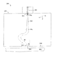
FIG. 1 is a perspective view of a slider assembly according to an example embodiment;
FIGS. 2A-B are cross-sectional views illustrating waveguide configurations according to example embodiments;
FIG. 3 is a graph illustrating reflected energy as a function of waveguide tilt angle according to example embodiments;
FIG. 4A is a cross-sectional view in the cross-track direction of an angled waveguide with a near field transducer according to an example embodiment;
FIG. 4B is a cross-sectional view in the down-track direction of the angled waveguide of FIG. 4A;
FIG. 5 is a graph illustrating near-field transducer efficiency as a function of the length of the near-field transducer according to an example embodiment;
FIG. 6 is a graph illustrating near-field transducer efficiency as a function of the peg height according to an example embodiment;
FIG. 7A is an amplitude profile for TE00 mode excitation;
FIG. 7B is an amplitude profile for TE10 mode excitation;
FIGS. 8A-B are cross-sectional views of shaped waveguides according to example embodiments;
FIG. 9 is a graph illustrating near-field transducer efficiency as a function of type and length of waveguide shaping according to example embodiments;
FIG. 10A is a profile of light absorption by a recording medium for TE00 mode excited energy according to an example embodiment;
FIG. 10B is a profile of light absorption by a recording medium for TE10 mode excited energy; and
FIG. 11 is a flowchart illustrating a method according to an example embodiment.
DETAILED DESCRIPTION
The present disclosure is generally related to the use of an angled waveguide (e.g., channel waveguide) that receives light from an energy source (e.g., laser diode) and delivers the light to a recording medium (e.g., a thermally-assisted, magnetic recording medium) at an angle other than normal to the output surface of a recording head. The waveguide is formed integrally within the recording head and additional recording head features (e.g., a near-field transducer) may also be formed at an angle. The laser diode may be attached to an outer surface of the recording head and direct its output to the waveguide at an angle approximately normal to the output surface of the recording head. The angle of the waveguide is selected to reduce reflection of the laser output from a recording medium and/or near-field transducer back to the laser diode. This reduction in reflection helps reduce laser instability issues including mode hopping.
A heat-assisted, magnetic recording (HAMR) data storage medium has a high magnetic coercivity that is able to overcome superparamagnetic effects (e.g., thermally-induced, random, changes in magnetic orientations) that currently limit the areal data density of conventional hard drive media. In a HAMR device, a small portion, or “hot spot,” of the magnetic medium is locally heated to its Curie temperature, thereby allowing magnetic orientation of the medium to be changed at the hot spot while being written to by a transducer (e.g., magnetic write pole). After the heat is removed, the region will maintain its magnetic state, thereby reliably storing the data for later retrieval.
A HAMR read/write element, sometimes referred to as a slider or read/write head, includes magnetic read and write transducers similar to those on current hard drives. For example, data may be read by a magnetoresistive sensor that detects magnetic fluctuations of the moving medium. Data may be written to the magnetic medium by a write coil that is magnetically coupled to a write pole. A HAMR slider will also generally include a source of energy, such as a laser diode, and an optical delivery path through the slider that delivers the energy to the surface of the medium.
The optical delivery path of a HAMR slider may include a near-field transducer (NFT) proximate a media-facing surface (e.g., air-bearing surface, contact surface). The NFT shapes and transmits the energy to a small region on the medium. The NFT is sometimes referred to as an optical antenna, surface plasmon resonator, etc. The NFT for a HAMR device is very small (e.g., on the order of 0.2λ to 2λ, λ denoting light wavelength for excitation) including a peg portion and an expanded portion and creates a localized region of high power density in the media through an electromagnetic interaction. This results in a high temperature rise in a small region on the media, with the region exceeding the Curie temperature having dimensions less than 100 nm.
A laser (or other energy source) may be separated from or attached to the HAMR slider. Configurations where a laser (e.g., edge-emitting or surface-emitting) is attached to the HAMR slider allows for parallel attachment of large numbers of lasers at once to a wafer of slider bodies, thereby reducing manufacturing costs. Depending on the orientation of the laser, light output of the laser may be parallel to the plane of the wafer to direct output energy at an angle approximately perpendicular, or normal, to the media-facing surface.
A light source such as an edge-emitting laser diode often has a fundamental, transverse electric mode, a TE00-like output beam profile. However, some configurations of a HAMR slider convert the light to TE10 mode. This can be done to utilize solid immersion mirrors to focus light delivery on NFTs with a lollipop shape, or to use a TE10 waveguide mode light delivery with a stadium-style NFT, where the stadium-style NFT has almost double the NFT width of a lollipop NFT. While these TE10 configurations can provide efficient light delivery to a recording medium, they can also yield significant reflected light returned to the energy source, e.g., laser diode. Largely angling a channel waveguide at the media-facing surface of a slider to deliver single transverse mode (TE00) light reduces light reflected back to the energy source. Embodiments described herein do not incorporate a mode order converter or a polarization converter thereby providing a simpler light path. Also, using a laser diode with transverse electric mode provides greater choices in laser emission wavelengths than lasers having transverse magnetic (TM) mode.
In embodiments described below, a waveguide is used to guide and direct energy from the laser diode to the recording medium. In reference to FIG. 1, a perspective view shows a HAMR slider assembly 100 according to an example embodiment. The slider assembly 100 includes an energy source 102 (e.g., laser diode) located on input surface 103 of a slider body 101. The energy source 102 delivers light to a region proximate a HAMR read/write head 106, which is located near a media-facing surface 108 of the slider body 101. The media-facing surface 108 faces and is held proximate to the moving medium surface during device operation. The media-facing surface 108 may be configured as an air-bearing surface (ABS) that maintains separation from the media surface via a thin layer of air.
The slider assembly 100 tracks across the magnetic recording medium in the x-axis of FIG. 1, also referred to as the cross-track direction. Relative to the slider, the magnetic recording medium rotates in the orthogonal y-axis direction, referred to as the down-track direction. The edge of the slider that first passes over any position of the rotating recording medium in the down-track direction is referred to as the leading edge, and the edge of the slider that is last to pass over the position of the recording medium is referred to as the trailing edge, designated by plane 104. The magnetic recording head arrangement, with slider assembly 100, reads and/or writes bits to the rotating magnetic recording medium as the magnetic recording medium rotates relative to the slider.
The energy source 102 provides electromagnetic energy used to heat the recording medium as it passes by the read/write head 106. Optical coupling components, such as a waveguide 110, are formed integrally within the slider assembly 100 and form an optical path that delivers energy from the energy source 102 to the recording medium via a near-field transducer (NFT) 112. The laser light can be focused on the NFT 112 with a variety of optical elements such as a tapered optical waveguide or a curved channel waveguide. The near-field transducer 112 is near the read/write head 106 and causes heating of the medium during recording operations.
In this example, the energy source is an edge-emitting laser that emits light from an elongated channel that has an output located near a corner edge of the laser. The edge-emitting laser is surface mounted on input surface 103 and emits light normal (or approximately so) to the input surface 103, e.g., along the z-direction. The waveguide 110 and variations thereof described herein may also be used with other types of laser diodes, such as vertical cavity, surface-emitting lasers (VCSELs). Generally, a VCSEL emits light in a direction perpendicular to a surface of the laser body. The energy source 102 may be mounted on a surface of the slider body 101 (or in a pocket or cavity). A surface-emitting or edge-emitting laser in any of these examples may be coupled to the slider body 101, or via a coupling component such as a submount (not shown).
The energy source 102 can be mounted external, or integral, to the magnetic recording head arrangement. While the example in FIG. 1 shows energy source 102 directly mounted to the slider assembly 100, the waveguide 110 discussed herein may be applicable to any type of light delivery configuration. For example, in a free-space light delivery configuration, a laser may be mounted externally to the slider, and coupled to the slider by way of optic fibers and/or waveguides. The slider in such an arrangement may include a coupling feature on an input surface 103 into which light is coupled and delivered to a waveguide 110 which propagates the light in a direction to energize the near-field transducer 112. As will be described in greater detail hereinbelow, the waveguide 110 facilitates directing light to the media-facing surface 108 at an angle other than normal in the cross-track (x-axis) direction of the media-facing surface 108.
In reference now to FIGS. 2A-B, two configurations for light delivery to a plasmonic near-field transducer (NFT) integrated with a writer are shown. In FIG. 2A, an energy source 202, such as a laser diode, launches light into a waveguide 210 on a slider assembly 200 by a waveguide input coupler 214. In certain embodiments, the laser diode 202 is an edge-emitting laser diode mounted on a submount. The laser diode 202 is polarized along the x direction (using the coordinates shown on FIGS. 2A-B), exciting a fundamental transverse electric mode (TE00) in the waveguide 210. The waveguide core dimension is selected to support only single transverse electric mode. An assistant layer underneath or above the waveguide core may be used to match the mode profile between the energy source 202 and the waveguide input coupler 214, such as a tapered input coupler, at the energy source/waveguide interface for efficient coupling between the energy source 202 and the waveguide 210. Examples of assistant waveguide core layers are further described in U.S. Pat. No. 8,385,183, which is incorporated herein.
Regardless of the presence of such assistant layers, the waveguide 210 includes at least one core layer surrounded by one or more cladding layers. The waveguide core is made of dielectric materials of high index of refraction, for example, Ta2O5 (tantalum oxide), TiO2 (titanium oxide), Nb2O5 (niobium oxide), SiNx (silicon nitride, including Si3N4), SiC (silicon carbon), Y2O3 (yttrium oxide), ZnSe (zinc selenide), ZnS (zinc sulfide), ZnTe (zinc telluride), Ba4Ti3O12 (barium titanate), GaP (gallium phosphide), CuO2 (copper oxide), and Si (silicon). The cladding layers are each formed of a dielectric material having a refractive index lower than that of the core; such materials may include Al2O3 (aluminum oxide), SiO (silicon oxide), SiO2 (silica), SiOxNy (silicon oxynitride), and AlN (aluminum nitride). The higher refractive index of the waveguide core facilitates efficient propagation of energy, e.g., light, through the waveguide 210.
Light, in the transverse electric mode, propagates along the waveguide 210 and excites a plasmonic NFT 212, which concentrates optical energy into a tiny spot 206 well below far-field diffraction limit and delivers this energy to a magnetic recording medium 204. The delivered energy heats the medium 204 during writing with a switching magnetic field from a magnetic pole (not shown).
The waveguide 210 is nearly normal to the energy source-facing surface 220 such that the light exiting from the energy source 202 is nearly normal to this surface 220 for coupling efficiency from energy source 202 to the waveguide 210. However, the waveguide 210 near the media-facing surface 208 is tilted, or angled, from a direction normal to the media-facing surface 208 (represented by the dashed line), e.g., angled from the z-axis of FIG. 2A. It can be seen in FIGS. 2A-B that while the waveguide 210 is disposed at an angle other than normal at the media-facing surface 208, the end portion of the waveguide 210 is flush with the media-facing surface 208. The angle at which the waveguide 210 is tilted from a direction normal to the media-facing surface 208 is selected to suppress return light reflected from the recording medium 204 and the near-field transducer/writer into the energy source 202 and can be a large angle as shown below in FIG. 3. Reflected light that reaches the energy source 202 can cause laser instability such as mode hopping.
Depending on the location of the energy source 202, the width and shape of the waveguide 210 can vary. For example, FIG. 2A shows an energy source 202 centered on slider 200. The waveguide 210 then bends, in an S-shaped curve, to provide an angled approach, in the cross-track direction (x-direction), to the media facing surface 208. In addition to the curving shape of the waveguide 210, the width of the waveguide 210, again in the cross-track direction, varies along the length of the waveguide 210. For example, a width at the input end of the waveguide 210, W0, accommodates an efficient coupling to the energy source 202. Further along the waveguide, in the z direction toward the media-facing surface 208, the width expands to width, W1, prior to, or part of initiating, the curvature. After the waveguide 210 attains the tilt angle, θ, for approaching the media-facing surface 208, width, W, is established. FIG. 2B shows an alternative configuration for slider 200. In FIG. 2B, the energy source 202 is positioned off-center on the input surface 220 of the slider 200. Here, the waveguide 210 includes one bend in the cross-track direction as the waveguide 210 attains the tilt angle, θ, toward the media-facing surface 208. Similar to FIG. 2A, the waveguide width can vary, e.g., gradually expand, along the length of the waveguide in the z-direction, at least up to the curvature in the waveguide 210. The changing widths accommodate both coupling the energy source 202 at the input surface 220 with an input coupler 214 as well as integrating an NFT 212 at the media-facing surface 208.
Since the features of a slider assembly, such as 200, can be manufactured by depositing a plurality of layers, the waveguide layers are disposed in a plane parallel to a deposition substrate. While the waveguide could be angled in any direction with respect to the media-facing surface 208, the waveguide 210 is shown here angled in the cross-track direction such that the waveguide 210 is created by a combination of masking and deposition steps. Thus, as shown, the waveguide 210, and NFT 212 can be angled with respect to the media-facing surface 208 in planes parallel to each other, as well as to other slider assembly features such as a write pole (not shown).
The tilt angle, θ, of the waveguide 210 is selected to minimize, or prevent, light being reflected from the recording medium's surface and the near-field transducer/writer from traveling back through the slider assembly 200 to the energy source 202. In certain embodiments, to determine the tilt angle θ, the return light is calculated through a channel waveguide coupled with a recording medium. In this modeling/calculation, there is no NFT or magnetic pole in the slider. A generic medium comprising an FePt layer (e.g., 15 nm thick with a complex refractive index n=2.55+j 2.72), an MgO layer (10 nm thick, n=1.70), a heat sink Cu layer (60 nm thick, n=0.26+j 5.29), and a glass substrate is assumed. The head to medium spacing (e.g., distance between the media-facing surface and the recording medium) is set at 10 nm with an effective index of n=1.21. The waveguide is composed of a TiOx core of refractive index of n=2.35, surrounded with SiO2 (n=1.46) cladding. The core is 390 nm wide (W) and 120 nm thick (along the y-axis of FIGS. 2A-B), and the light wavelength (λ) is 830 nm.
FIG. 3 is a graph showing the amount of detected return transverse electric mode (TE00) light reflected from a recording medium as a function of the waveguide tilt angle, θ, at the media-facing surface. The tested medium is highly reflective. For example, at a tilt angle of five degrees (θ=5°), the amount of returned TE00 mode reaches 45%. As the tilt angle increases, e.g., θ>25°, the returned light decreases substantially. To obtain a return light below 0.1%, the tilt angle, θ, should be equal to or greater than 30° from normal to the media-facing surface. In addition to tilting the waveguide, the NFT, or a portion thereof, can also be tilted.
FIGS. 4A-B illustrate cross-sections of an NFT 412 with TE00 waveguide mode excitation and angled with an angled waveguide core 410 in accordance with example embodiments. FIG. 4A shows a cross-section of a waveguide core 410 and NFT 412 on a plane parallel to the waveguide in the cross-track direction (x-direction) of a slider. The waveguide core 410 near the media-facing surface 408 is tilted at an angle, θ, from a direction normal to the media facing surface 408 (represented by dashed line 450). The angle, θ, is an oblique angle to a cross-track line at an intersection of the media-facing surface 408 and a substrate-parallel plane, which refers to the substrate upon which the layers of the slider are deposited and is substantially normal to the media-facing surface 408. In addition to angling the waveguide core 410 at the media-facing surface 408, the NFT 412 can also be shaped and angled.
The NFT 412 has an enlarged portion 414 having a tear-drop shape with two curved, circular ends 416, 418 and with a protruded peg 420. The NFT 412 is located at the top cladding layer of the waveguide 430 and proximate the waveguide core 410. A first, top end 416 is positioned away from the media-facing surface 408 and first receives the incoming energy guided by the waveguide core 410. The first end 416 has a first radius, R1, and is convex shaped, which reduces reflection of the incoming light onto it. A second, bottom end 418 is positioned closer to the media-facing surface 408 and couples to the peg 420. The second end 418 has a second radius, R2, and is also convex-shaped, which improves the impedance match between the enlarged portion 414 and the peg 420 such that the impedance gradually increases. The circular first and second ends, in some embodiments, have radii where R2≧R1 for NFT efficiency. The middle section of the enlarged portion 414 has a length, L, and is shown with straight sides that connect the first and second circular ends.
The enlarged portion of the NFT 414 is nearly centered along the waveguide core's center line (shown as dashed line 452), but the peg 420 is positioned off the waveguide core's center line. The enlarged portion 414 might also be off the waveguide core's center line to mitigate the reflection from the recording medium 404 and near-field transducer/writer. The peg 420 is substantially normal to the media-facing surface 408 and is coupled with the enlarged portion of the NFT 414 at the portion protruding closest to the media-facing surface 408, e.g., the portion of the second end 418 closest to the media-facing surface 408. The peg can be positioned along the x direction about 10-30 nm to the left (i.e., negative x direction in the figure) from the most protruding position of the enlarged portion 414. Although not shown, the peg 420 can also be slanted, similar to the enlarged portion 414, to improve the thermal gradient and to reduce the peg 420 temperature. The NFT 412 interacts with the TE00 waveguide mode, generating local surface plasmon at the circumference of the enlarged portion of the NFT 414. Charges funnel into the peg 420 resulting in lightning effect. Several dimensions can be altered to affect the efficiency of NFT 412 excitation such as the waveguide core dimensions (e.g, width and angle), shape of the NFT (e.g., end curvatures R1, R2 and length, L), and the peg height (along the z-direction).
In FIG. 4B, the waveguide core 410 and NFT 412 of FIG. 4A are shown in cross-section in the down-track direction (e.g., rotated ninety degrees from the view of FIG. 4A) proximate a recording medium 404. The arrow represents light in the fundamental transverse electric mode being guided by the waveguide core 410 and both the top cladding 430 and bottom cladding 432 are shown. In addition to the waveguide core 410 and NFT 412, a magnetic pole 440 and heatsink 438 are shown. The magnetic pole 440 is positioned approximately 20-50 nm from the NFT 412. The heatsink 438 for the NFT 412 can take various sizes, shapes, and locations including, but not limited to, the same footprint as the enlarged portion 414, smaller than the enlarged portion 414, and recessed from the media-facing surface 408. The various heatsink 438 configurations affect the thermal gradient resulting in sharp write magnetic transitions.
To determine various NFT 412 dimensions (e.g., R1, R2 and length, L) and evaluate the performance of an NFT 412 according to embodiments disclosed herein, NFT efficiency, CE50, is measured. NFT efficiency, CE50, is defined as the light absorption in the FePt layer of a magnetic medium in a foot print of 50 nm by 50 nm. In measuring the NFT efficiency, as shown in the results of FIG. 5 to evaluate the length of the enlarged portion of the NFT, it is assumed that no magnetic pole was present. The thickness of the enlarged portion of the NFT in the y-direction (using the coordinates of FIGS. 4A-B) is 60 nm. Also, the peg dimensions are set at 30 nm thick along the y-direction, 60 nm wide along the x-direction, and 20 nm high along the z-direction. The NFT is made of gold, and both the enlarged portion of the NFT and the peg are positioned 20 nm away from the waveguide core. While the radii of the first and second circular ends of the NFT enlarged portion can vary, a first radius, R1, of approximately 80 nm and a second radius, R2 of approximately 110 nm were used. These dimensions are similar to the enlarged, disc portion of a lollipop-style NFT but are approximately half the size of an NFT with a first higher order TE10 mode excitation. A narrower NFT width may benefit NFT reliability in a peg recess due to vacancy migration from the enlarged portion of the NFT to the peg.
FIG. 5 illustrates NFT efficiency as a function of the NFT length, the dimension along the waveguide, when the waveguide tilt angle was set at forty-five degrees. It can be seen that the NFT efficiency oscillates with increasing NFT length, L, with a period of approximately 180 nm. There are two noticeable peaks of improved efficiency at lengths of 430 nm and at 610 nm in the length range that was measured. These dimensions can be used to compare an NFT according to embodiments disclosed herein, with an NFT utilizing TE10 mode excitation.
FIG. 6 illustrates a comparison of NFT efficiency of an NFT with TE00 mode excitation, according to embodiments herein, with an NFT with TE10 mode excitation with respect to varying peg heights (z-direction dimension). Using the NFT and waveguide core dimensions set forth above along with an NFT enlarged portion length of 610 nm, an NFT with TE00 mode excitation includes a slanted magnetic pole connected with the NFT via a gold heatsink for the comparison. The magnetic pole is 200 nm wide, wrapped with a Cr heatsink, and spaced 20 nm from the NFT at the media-facing surface. The total width of the pole (along x-direction) including the Cr heatsink is 600 nm, and the heatsink/pole is truncated at the far end of the NFT. Similar to the above peg dimensions, the peg is 30 nm thick along the y-direction, but here is 40 nm wide along the x-direction. As can be seen in FIG. 6, both mode profiles provide similar NFT efficiency, but the NFT with TE00 mode excitation has a lower sensitivity to peg height. The modeling also shows that the absorption in the peg between the two designs is comparable.
The NFT efficiency can also be varied by altering waveguide core dimensions such as the cross-section and/or tilt angle. For example, changing the tilt angle to fifty-five degrees increases the NFT efficiency by fifteen percent. When altering the waveguide dimensions, the waveguide core can be made thinner (along the y-direction) and wider (e.g., dimension, W, in FIG. 2A) to keep the waveguide as a single mode and to have a preselected mode index. In certain embodiments, the waveguide core can be altered from 390 nm by 120 nm to 510 nm by 100 nm to increase NFT efficiency by twenty percent without the presence of a magnetic pole, or by five percent with the presence of a magnetic pole and NFT heatsink. This change reduces bending loss when forming the tilted waveguide normal to an input surface of a slider and reduces scattering loss from waveguide core sidewall roughness.
Increased NFT efficiency can also increase background heating in the recording medium; however, such direct heating of the medium from the waveguide core is not beneficial in HAMR. Since the fundamental mode (TE00) has a more concentrated energy density than TE10 mode, background heating in the recording medium from residue TE00 mode excitation is usually greater than that of waveguides delivering TE10 mode energy. FIG. 7A illustrates a mode profile for TE00 mode excitation and FIG. 7B illustrates a mode profile for TE10 mode excitation. The core dimensions for the waveguide of FIG. 7A are 510 nm by 100 nm, and the core dimensions for the waveguide of FIG. 7B are 750 nm by 120 nm. As can be seen, the peak amplitude in FIG. 7A is 64.9 for the TE00 mode; whereas, the peak amplitude for the TE10 mode is 50.4. Thus, the power density ratio between the two modes is approximately (64.9/50.4)2=1.66. However, tilting the waveguide core, as described in various embodiments herein, for a TE00 mode waveguide reduces this power density by cos(θ). If the tilt angle is forty-five degrees, this would be 0.71, and if the tilt angle is fifty-five degrees, this would be 0.57. For example, a tilt angle of forty-five degrees reduces the peak power density ratio to 1.17. In addition to the excitation mode, radiation of the NFT to the recording medium also contributes to background heating.
NFT radiation-based background heating can be reduced by altering the waveguide core 810 dimensions. For example, the waveguide core 810 can be shaped asymmetrically at the output end to reduce the NFT radiation reaching the medium. FIGS. 8A and 8B illustrate alternative examples for shaping the output end of the waveguide core 810 to reduce the footprint of the waveguide core 810 at the media-facing surface 808. The waveguide core 810 includes two illustrated sidewalls 814, 816. Sidewall 814 is positioned closer to the media-facing surface 808 as a result of the angled approach of the waveguide core 810 toward the media-facing surface 808. In FIG. 8A, a stepped reduction in the width of waveguide core 810 is shown by reducing the width/distance of sidewall 814 from the waveguide core 810 center line (represented by dashed line 822). For example, the distance between sidewall 814 and center line 822 is reduced at a sharp angle (e.g., ninety degrees) for a designated distance (e.g., ΔW). Then sidewall 814 mirrors the original tilt angle at the new distance from the center line 822 along the length of the waveguide core 810 to the media-facing surface 808. The shaping length, e.g., the distance from the media-facing surface at which the waveguide core 810 width reduction begins, is designated as L0. Although the cross-section of the output end of the waveguide core 810 is reduced, the width of the NFT (both the enlarged portion 818 and the peg 820) remains less than the width of sidewalls 814, 816 of waveguide core 810 at the output end of the waveguide core 810.
FIG. 8B also shows a reduction in the cross-track width of the waveguide core 810 at the media-facing surface 808, but the reduction is achieved by tapering sidewall 814. Similarly to FIG. 8A, the shaping length, e.g., the distance from the media-facing surface at which the tapering begins, is designated as L0. Here, the change in width, ΔW, effected on sidewall 814 can be measured at the media-facing surface 808 by comparing the difference between the cross-track location where sidewall 814 reaches the media-facing surface 808 and the cross-track location where sidewall 814 would have reached the media-facing surface 808 with the original tilt angle. In embodiments where the waveguide core 810 is shaped via tapering, the sidewalls 814, 816 intercept the media-facing surface 808 at different angles with respect to normal. While both of these shaping configurations reduce background heating, their effectiveness can be compared by measuring NFT efficiency for each configuration.
FIG. 9 is a graph comparing the NFT efficiency as a function of the shaping length, L0, for both a tapered shaping and a stepped shaping of a waveguide core. For both shaping configurations, the change in width, ΔW, is 150 nm. The modeling was performed with the presence of a magnetic pole and NFT heatsink. As long as the shaping length is at least the length of the NFT, the NFT efficiency improves and the peak background heating can be reduced by 25-35%. This reduction can, at least partly, compensate for the increased background heating due to the fundamental mode excitation by bringing the background heating to a level comparable to a waveguide with TE10 mode excitation.
FIGS. 10A and 10B illustrate this reduction in background heating. FIG. 10A is an absorption profile at the middle plane of a recording layer of a medium exposed to an angled waveguide core and NFT with TE00 mode excitation according to embodiments described herein. FIG. 10B is an absorption profile at the middle plane of a recording layer of a medium exposed to a waveguide core and NFT with TE10 mode excitation. FIG. 10A shows some background absorption on the lower left side of the NFT hot spot while FIG. 10B shows background absorption behind the NFT hot spot. However, the amount of background absorption in both figures is comparable. Similarly, full-width-at-half-maximum (FWHM) of both hot spots is comparable with 65 nm in the cross-track direction and 58 nm in the down-track direction. Modeling further shows that the return, or reflected, TE00 mode is about 0.028% for a fully integrated head. This includes an NFT, magnetic pole, NFT heatsink, and asymmetric waveguide shaping. At this level, the return light would not result in laser instability such as mode hopping.
In reference now to FIG. 11, a flowchart illustrates a method according to an example embodiment. The method involves emitting 1102 energy, e.g., laser light polarized in a fundamental transverse electric (TE00) mode, from a laser to an input surface of an input region of a recording head. The input surface is substantially parallel to a media-facing surface, and the light may be (although is not required to be) emitted normal to the input surface. In response to emitting 1102 the light, the light is received 1104 in the TE00 mode with an input end of a waveguide proximate the input surface. The waveguide guides the light in the TE00 mode to an output end proximate an output surface of the recording head, such as the media-facing surface, at an angle other than normal 1106 to the output surface. The output end is at an oblique angle to a cross-track line at an intersection of the output surface and a plane normal to the output surface. However, the waveguide may be disposed at an angle substantially normal to the input surface at the input surface.
In addition, the light in the TE00 mode is guided to an NFT proximate the output end of the waveguide. The NFT comprises an enlarged portion and a peg, and the enlarged portion comprises first and second curved ends connected by straight sides and is oriented at the oblique angle to the cross-track line. For example, each of the angled components can be disposed at an angle of greater than thirty degrees from a position normal to the output surface. The angle of the waveguide may be selected so as to reduce reflection of light back to the laser from the recording medium and other components, such as the NFT and magnetic writer, proximate the output surface. The light may also be guided through a curved bend in the waveguide between the input end and output end, and the width of the waveguide in the cross-track direction can vary between the input end and output end of the waveguide.
Energy is then delivered 1108 to heat a portion of a recording medium via the NFT. Optionally, a magnetic field may be applied 1110 to the portion of the recording medium as it is being heated. In this way, the magnetic field records data to the recording medium.
An NFT and light path (e.g., waveguide) in accordance with various embodiments described herein deliver light in the fundamental transverse electric (TE00) mode. Angling the waveguide at an oblique angle (e.g., greater than thirty degrees) from a direction normal to the media-facing surface efficiently excites a similarly angled NFT and reduces return light reflected from a recording medium below 0.1% to provide laser stability. Asymmetric waveguide shaping and waveguide angling at the media-facing surface reduce the direct heating in the recording medium from the reside waveguide mode to a level comparable with the direct heating experienced by exposure to a light path and NFT with TE10 mode excitation.
Unless otherwise indicated, all numbers expressing feature sizes, amounts, and physical properties used in the specification and claims are to be understood as being modified in all instances by the term “about.” Accordingly, unless indicated to the contrary, the numerical parameters set forth in the foregoing specification and attached claims are approximations that can vary depending upon the desired properties sought to be obtained by those skilled in the art utilizing the teachings disclosed herein. The use of numerical ranges by endpoints includes all numbers within that range (e.g. 1 to 5 includes 1, 1.5, 2, 2.75, 3, 3.80, 4, and 5) and any range within that range.
The foregoing description of the example embodiments has been presented for the purposes of illustration and description. It is not intended to be exhaustive or to limit the inventive concepts to the precise form disclosed. Many modifications and variations are possible in light of the above teaching. Any or all features of the disclosed embodiments can be applied individually or in any combination are not meant to be limiting, but purely illustrative. It is intended that the scope be limited not with this detailed description, but rather determined by the claims appended hereto.

Claims (20)

What is claimed is:
1. An apparatus, comprising:
a waveguide having an input end that receives energy in a transverse electric (TE00) mode from an energy source along a substrate-parallel plane;
a near-field transducer located proximate an output end of the waveguide and receiving the energy in the TE00 mode, the output end of the waveguide being at an oblique angle to a cross-track line at an intersection of a media-facing surface and the substrate-parallel plane, the near-field transducer comprising:
an enlarged portion comprising first and second curved ends connected by straight sides, the enlarged portion at the oblique angle to the cross-track line; and
a peg extending from the enlarged portion towards the media-facing surface, the peg at an angle about normal to the cross-track line.
2. The apparatus of claim 1, wherein the first curved end faces the media-facing surface and has a radius greater than a radius of the second circular end.
3. The apparatus of claim 1, wherein the oblique angle is selected to minimize reflections of the energy back to the energy source.
4. The apparatus of claim 1, wherein the input end of the waveguide is normal to the media-facing surface.
5. The apparatus of claim 4, wherein the waveguide comprises a curved bend between the input end and output end.
6. The apparatus of claim 4, wherein the waveguide comprises an S-bend between the input end and output end.
7. The apparatus of claim 1, wherein the width of the waveguide in a cross-track direction varies between the input end and output end.
8. The apparatus of claim 7, wherein the output end of the waveguide is asymmetrical.
9. The apparatus of claim 8, wherein the output end of the waveguide comprises a taper in the cross-track direction toward the media-facing surface.
10. The apparatus of claim 8, wherein the output end of the waveguide comprises a stepped reduction in width in the cross-track direction.
11. An apparatus, comprising:
a waveguide having an input end that receives energy in a transverse electric (TE00) mode from an energy source along a substrate-parallel plane and an output end, wherein a width of the waveguide in a cross-track direction varies between the input end and the output end;
a near-field transducer located proximate the output end of the waveguide and receiving the energy in the TE00 mode, the output end of the waveguide being at an oblique angle to a cross-track line at an intersection of a media-facing surface and the substrate-parallel plane, the near-field transducer comprising:
an enlarged portion comprising first and second curved ends connected by straight sides, the enlarged portion at the oblique angle to the cross-track line; and
a peg extending from the enlarged portion towards the media-facing surface, the peg at an angle about normal to the cross-track line.
12. The apparatus of claim 11, wherein the first curved end faces the media-facing surface and has a radius greater than a radius of the second curved end.
13. The apparatus of claim 11, wherein the input end of the waveguide is normal to the media-facing surface.
14. The apparatus of claim 13, wherein the waveguide comprises a curved bend between the input end and output end.
15. The apparatus of claim 11, wherein the output end of the waveguide is asymmetrical.
16. The apparatus of claim 11, wherein the oblique angle is selected to minimize reflections of the energy back to the energy source.
17. A method comprising:
emitting energy in a transverse electric (TE00) mode from an energy source to an input surface of a recording head;
receiving the energy in the TE00 mode with an input end of a waveguide proximate the input surface;
guiding the energy in the TE00 mode to an output end of the waveguide proximate an output surface of the recording head, the output end being at an oblique angle to a cross-track line at an intersection of the output surface and a plane normal to the output surface, and to a near field transducer proximate the output end, wherein the near field transducer comprises an enlarged portion and a peg, the enlarged portion comprising first and second circular ends connected by straight sides and oriented at the oblique angle to the cross-track line; and
delivering energy to heat a portion of a recording medium via the near field transducer.
18. The method of claim 17, wherein the input end of the waveguide is normal to the input surface and the output surface.
19. The method of claim 18, wherein the energy is guided through a curved bend in the waveguide between the input end and output end.
20. The method of claim 17, wherein the width of the waveguide in the cross-track direction varies between the input end and output end.
US14/928,611 2015-10-30 2015-10-30 Angled near-field transducer and waveguide Expired - Fee Related US9659590B1 (en)

Priority Applications (1)

Application Number Priority Date Filing Date Title
US14/928,611 US9659590B1 (en) 2015-10-30 2015-10-30 Angled near-field transducer and waveguide

Applications Claiming Priority (1)

Application Number Priority Date Filing Date Title
US14/928,611 US9659590B1 (en) 2015-10-30 2015-10-30 Angled near-field transducer and waveguide

Publications (2)

Publication Number Publication Date
US20170125048A1 US20170125048A1 (en) 2017-05-04
US9659590B1 true US9659590B1 (en) 2017-05-23

Family

ID=58635679

Family Applications (1)

Application Number Title Priority Date Filing Date
US14/928,611 Expired - Fee Related US9659590B1 (en) 2015-10-30 2015-10-30 Angled near-field transducer and waveguide

Country Status (1)

Country Link
US (1) US9659590B1 (en)

Cited By (1)

* Cited by examiner, † Cited by third party
Publication number Priority date Publication date Assignee Title
US10811043B2 (en) 2017-07-25 2020-10-20 Seagate Technology Llc Mode splitter between TE and TM polarization for heat-assisted magnetic recording device

Families Citing this family (2)

* Cited by examiner, † Cited by third party
Publication number Priority date Publication date Assignee Title
US10170140B2 (en) * 2017-01-23 2019-01-01 Seagate Technology Llc Waveguide having mode converter for heat-assisted magnetic recording device
US12444436B1 (en) * 2024-05-30 2025-10-14 Headway Technologies, Inc. Parabolic shaped plasmonic waveguide blocker for heat assisted recording head

Citations (18)

* Cited by examiner, † Cited by third party
Publication number Priority date Publication date Assignee Title
US2914741A (en) 1957-08-29 1959-11-24 Bell Telephone Labor Inc Waveguide bend
US5200939A (en) 1988-08-05 1993-04-06 Matsushita Electric Industrial Co., Ltd. Optical head apparatus including a waveguide layer with concentric or spiral periodic structure
US6388840B1 (en) * 1997-09-10 2002-05-14 Fujitsu Limited Suspension having a head IC mounting portion formed on a rigid portion between a base portion and a head slider mounting portion
US20080204916A1 (en) 2007-02-22 2008-08-28 Takuya Matsumoto Thermally assisted magnetic recording head and magnetic recording apparatus
US20100238580A1 (en) 2009-03-19 2010-09-23 Tdk Corporation Thermally-assisted magnetic recording head with light source on element-integration surface
US20110122737A1 (en) 2009-11-20 2011-05-26 Tdk Corporation Thermally-Assisted Magnetic Recording Head with Light Detector in Element-Integration Surface
US20110181979A1 (en) 2010-01-25 2011-07-28 Headway Technologies, Inc. Shaped plasmon generators for thermally-assisted magnetic recording
US20130223196A1 (en) 2012-02-23 2013-08-29 Seagate Technology Llc Plasmonic funnel for focused optical delivery to a metallic medium
US20140036646A1 (en) 2012-07-31 2014-02-06 Seagate Technology Llc Near-field transducer
US8670294B1 (en) 2012-02-17 2014-03-11 Western Digital (Fremont), Llc Systems and methods for increasing media absorption efficiency using interferometric waveguides
US8670295B1 (en) 2010-12-20 2014-03-11 Western Digital (Fremont), Llc Method and system for optically coupling a laser with a transducer in an energy assisted magnetic recording disk drive
US20140241137A1 (en) 2013-02-27 2014-08-28 Headway Technologies, Inc. Tilted Structures to Reduce Reflection in Laser-Assisted TAMR
US8861124B1 (en) 2013-03-14 2014-10-14 Western Digital (Fremont), Llc Integrated sensor for monitoring laser power in a heat assisted magnetic recording disk drive
US20140325827A1 (en) 2011-12-19 2014-11-06 Cornell University Controlled inter-mode cross-talk in optical waveguides
US20150109822A1 (en) 2012-05-16 2015-04-23 3M Innovative Properties Company Illumination converter
US20150318005A1 (en) 2014-04-30 2015-11-05 HGST Netherlands B.V. Waveguide power sensor structures free of optical coherence effects in a hamr drive
US9251819B2 (en) 2013-11-12 2016-02-02 Seagate Technology Llc Mode converter coupling energy at a high-order transverse electric mode to a plasmonic transducer
US9336814B1 (en) * 2013-03-12 2016-05-10 Western Digital (Fremont), Llc Inverse tapered waveguide for use in a heat assisted magnetic recording head

Patent Citations (18)

* Cited by examiner, † Cited by third party
Publication number Priority date Publication date Assignee Title
US2914741A (en) 1957-08-29 1959-11-24 Bell Telephone Labor Inc Waveguide bend
US5200939A (en) 1988-08-05 1993-04-06 Matsushita Electric Industrial Co., Ltd. Optical head apparatus including a waveguide layer with concentric or spiral periodic structure
US6388840B1 (en) * 1997-09-10 2002-05-14 Fujitsu Limited Suspension having a head IC mounting portion formed on a rigid portion between a base portion and a head slider mounting portion
US20080204916A1 (en) 2007-02-22 2008-08-28 Takuya Matsumoto Thermally assisted magnetic recording head and magnetic recording apparatus
US20100238580A1 (en) 2009-03-19 2010-09-23 Tdk Corporation Thermally-assisted magnetic recording head with light source on element-integration surface
US20110122737A1 (en) 2009-11-20 2011-05-26 Tdk Corporation Thermally-Assisted Magnetic Recording Head with Light Detector in Element-Integration Surface
US20110181979A1 (en) 2010-01-25 2011-07-28 Headway Technologies, Inc. Shaped plasmon generators for thermally-assisted magnetic recording
US8670295B1 (en) 2010-12-20 2014-03-11 Western Digital (Fremont), Llc Method and system for optically coupling a laser with a transducer in an energy assisted magnetic recording disk drive
US20140325827A1 (en) 2011-12-19 2014-11-06 Cornell University Controlled inter-mode cross-talk in optical waveguides
US8670294B1 (en) 2012-02-17 2014-03-11 Western Digital (Fremont), Llc Systems and methods for increasing media absorption efficiency using interferometric waveguides
US20130223196A1 (en) 2012-02-23 2013-08-29 Seagate Technology Llc Plasmonic funnel for focused optical delivery to a metallic medium
US20150109822A1 (en) 2012-05-16 2015-04-23 3M Innovative Properties Company Illumination converter
US20140036646A1 (en) 2012-07-31 2014-02-06 Seagate Technology Llc Near-field transducer
US20140241137A1 (en) 2013-02-27 2014-08-28 Headway Technologies, Inc. Tilted Structures to Reduce Reflection in Laser-Assisted TAMR
US9336814B1 (en) * 2013-03-12 2016-05-10 Western Digital (Fremont), Llc Inverse tapered waveguide for use in a heat assisted magnetic recording head
US8861124B1 (en) 2013-03-14 2014-10-14 Western Digital (Fremont), Llc Integrated sensor for monitoring laser power in a heat assisted magnetic recording disk drive
US9251819B2 (en) 2013-11-12 2016-02-02 Seagate Technology Llc Mode converter coupling energy at a high-order transverse electric mode to a plasmonic transducer
US20150318005A1 (en) 2014-04-30 2015-11-05 HGST Netherlands B.V. Waveguide power sensor structures free of optical coherence effects in a hamr drive

Non-Patent Citations (1)

* Cited by examiner, † Cited by third party
Title
File History for U.S. Appl. No. 14/995,754 retrieved from the U.S. Patent and Trademark Office PAIR System on Aug. 31, 2016, 83 pages.

Cited By (1)

* Cited by examiner, † Cited by third party
Publication number Priority date Publication date Assignee Title
US10811043B2 (en) 2017-07-25 2020-10-20 Seagate Technology Llc Mode splitter between TE and TM polarization for heat-assisted magnetic recording device

Also Published As

Publication number Publication date
US20170125048A1 (en) 2017-05-04

Similar Documents

Publication Publication Date Title
US8730780B2 (en) Light delivery waveguide
US9978409B2 (en) Offset waveguide system with a mode converter and a tapered bend
US9449626B2 (en) Structure positioned between magnetic pole and near-field transducer
US9099130B2 (en) Plasmonic waveguide with an angled, elongated portion
US8929698B2 (en) Plasmonic transducer with reduced cross section at media-reading surface
US20150131415A1 (en) Mode converter coupling energy at a high-order transverse electric mode to a plasmonic transducer
US10811043B2 (en) Mode splitter between TE and TM polarization for heat-assisted magnetic recording device
US9633683B2 (en) Mode conversion via tapered waveguide
US10127938B2 (en) Method for forming TE to TM mode converter of heat-assisted magnetic recording head
US9047912B1 (en) Write head mode optical mode converter using three-dimensional waveguide and dual-mode waveguide
US9449627B2 (en) Angled waveguide
US9934800B1 (en) Plasmonic coupler used with near-field transducer
US9659591B1 (en) Polynomial spiral waveguide that facilitates coupling light to a near-field transducer at an oblique angle
US20150235658A1 (en) Heat sink layer along an aperture of a near-field transducer
US9659590B1 (en) Angled near-field transducer and waveguide
US10734019B1 (en) Curved-edge optical mode converter for heat-assisted magnetic recording
US11373679B1 (en) Recording head with focusing structure
US9202491B2 (en) Planar plasmon generator with thickened region and peg region
US9946016B2 (en) Waveguide with shaped assistant layer
US10242702B1 (en) Near-field transducer with stacked features that reduce emission of polarization-rotated light
US9905253B1 (en) C-shaped near-field transducer including a peg for heat-assisted magnetic recording device
US12106771B2 (en) Laser feedback suppressor for heat-assisted magnetic recording
US11443764B1 (en) Waveguide having plasmonic strips for heat-assisted magnetic recording

Legal Events

Date Code Title Description
AS Assignment

Owner name: SEAGATE TECHNOLOGY LLC, CALIFORNIA

Free format text: ASSIGNMENT OF ASSIGNORS INTEREST;ASSIGNOR:PENG, CHUBING;REEL/FRAME:037450/0204

Effective date: 20151102

FEPP Fee payment procedure

Free format text: PAYOR NUMBER ASSIGNED (ORIGINAL EVENT CODE: ASPN); ENTITY STATUS OF PATENT OWNER: LARGE ENTITY

STCF Information on status: patent grant

Free format text: PATENTED CASE

MAFP Maintenance fee payment

Free format text: PAYMENT OF MAINTENANCE FEE, 4TH YEAR, LARGE ENTITY (ORIGINAL EVENT CODE: M1551); ENTITY STATUS OF PATENT OWNER: LARGE ENTITY

Year of fee payment: 4

FEPP Fee payment procedure

Free format text: MAINTENANCE FEE REMINDER MAILED (ORIGINAL EVENT CODE: REM.); ENTITY STATUS OF PATENT OWNER: LARGE ENTITY

LAPS Lapse for failure to pay maintenance fees

Free format text: PATENT EXPIRED FOR FAILURE TO PAY MAINTENANCE FEES (ORIGINAL EVENT CODE: EXP.); ENTITY STATUS OF PATENT OWNER: LARGE ENTITY

STCH Information on status: patent discontinuation

Free format text: PATENT EXPIRED DUE TO NONPAYMENT OF MAINTENANCE FEES UNDER 37 CFR 1.362

FP Lapsed due to failure to pay maintenance fee

Effective date: 20250523