US9655732B2 - Joint prosthesis attachment system, device and method - Google Patents
Joint prosthesis attachment system, device and method Download PDFInfo
- Publication number
- US9655732B2 US9655732B2 US14/511,967 US201414511967A US9655732B2 US 9655732 B2 US9655732 B2 US 9655732B2 US 201414511967 A US201414511967 A US 201414511967A US 9655732 B2 US9655732 B2 US 9655732B2
- Authority
- US
- United States
- Prior art keywords
- socket
- support body
- joint component
- contact arms
- surgical method
- Prior art date
- Legal status (The legal status is an assumption and is not a legal conclusion. Google has not performed a legal analysis and makes no representation as to the accuracy of the status listed.)
- Expired - Fee Related, expires
Links
Images


Classifications
-
- A—HUMAN NECESSITIES
- A61—MEDICAL OR VETERINARY SCIENCE; HYGIENE
- A61F—FILTERS IMPLANTABLE INTO BLOOD VESSELS; PROSTHESES; DEVICES PROVIDING PATENCY TO, OR PREVENTING COLLAPSING OF, TUBULAR STRUCTURES OF THE BODY, e.g. STENTS; ORTHOPAEDIC, NURSING OR CONTRACEPTIVE DEVICES; FOMENTATION; TREATMENT OR PROTECTION OF EYES OR EARS; BANDAGES, DRESSINGS OR ABSORBENT PADS; FIRST-AID KITS
- A61F2/00—Filters implantable into blood vessels; Prostheses, i.e. artificial substitutes or replacements for parts of the body; Appliances for connecting them with the body; Devices providing patency to, or preventing collapsing of, tubular structures of the body, e.g. stents
- A61F2/02—Prostheses implantable into the body
- A61F2/30—Joints
- A61F2/40—Joints for shoulders
- A61F2/4081—Glenoid components, e.g. cups
-
- A—HUMAN NECESSITIES
- A61—MEDICAL OR VETERINARY SCIENCE; HYGIENE
- A61F—FILTERS IMPLANTABLE INTO BLOOD VESSELS; PROSTHESES; DEVICES PROVIDING PATENCY TO, OR PREVENTING COLLAPSING OF, TUBULAR STRUCTURES OF THE BODY, e.g. STENTS; ORTHOPAEDIC, NURSING OR CONTRACEPTIVE DEVICES; FOMENTATION; TREATMENT OR PROTECTION OF EYES OR EARS; BANDAGES, DRESSINGS OR ABSORBENT PADS; FIRST-AID KITS
- A61F2/00—Filters implantable into blood vessels; Prostheses, i.e. artificial substitutes or replacements for parts of the body; Appliances for connecting them with the body; Devices providing patency to, or preventing collapsing of, tubular structures of the body, e.g. stents
- A61F2/02—Prostheses implantable into the body
- A61F2/30—Joints
- A61F2/30721—Accessories
- A61F2/30734—Modular inserts, sleeves or augments, e.g. placed on proximal part of stem for fixation purposes or wedges for bridging a bone defect
-
- A—HUMAN NECESSITIES
- A61—MEDICAL OR VETERINARY SCIENCE; HYGIENE
- A61B—DIAGNOSIS; SURGERY; IDENTIFICATION
- A61B17/00—Surgical instruments, devices or methods
- A61B17/56—Surgical instruments or methods for treatment of bones or joints; Devices specially adapted therefor
- A61B17/58—Surgical instruments or methods for treatment of bones or joints; Devices specially adapted therefor for osteosynthesis, e.g. bone plates, screws or setting implements
- A61B17/68—Internal fixation devices, including fasteners and spinal fixators, even if a part thereof projects from the skin
- A61B17/84—Fasteners therefor or fasteners being internal fixation devices
- A61B17/86—Pins or screws or threaded wires; nuts therefor
-
- A—HUMAN NECESSITIES
- A61—MEDICAL OR VETERINARY SCIENCE; HYGIENE
- A61F—FILTERS IMPLANTABLE INTO BLOOD VESSELS; PROSTHESES; DEVICES PROVIDING PATENCY TO, OR PREVENTING COLLAPSING OF, TUBULAR STRUCTURES OF THE BODY, e.g. STENTS; ORTHOPAEDIC, NURSING OR CONTRACEPTIVE DEVICES; FOMENTATION; TREATMENT OR PROTECTION OF EYES OR EARS; BANDAGES, DRESSINGS OR ABSORBENT PADS; FIRST-AID KITS
- A61F2/00—Filters implantable into blood vessels; Prostheses, i.e. artificial substitutes or replacements for parts of the body; Appliances for connecting them with the body; Devices providing patency to, or preventing collapsing of, tubular structures of the body, e.g. stents
- A61F2/02—Prostheses implantable into the body
- A61F2/30—Joints
- A61F2002/30001—Additional features of subject-matter classified in A61F2/28, A61F2/30 and subgroups thereof
- A61F2002/30316—The prosthesis having different structural features at different locations within the same prosthesis; Connections between prosthetic parts; Special structural features of bone or joint prostheses not otherwise provided for
- A61F2002/30329—Connections or couplings between prosthetic parts, e.g. between modular parts; Connecting elements
- A61F2002/30331—Connections or couplings between prosthetic parts, e.g. between modular parts; Connecting elements made by longitudinally pushing a protrusion into a complementarily-shaped recess, e.g. held by friction fit
- A61F2002/30332—Conically- or frustoconically-shaped protrusion and recess
-
- A—HUMAN NECESSITIES
- A61—MEDICAL OR VETERINARY SCIENCE; HYGIENE
- A61F—FILTERS IMPLANTABLE INTO BLOOD VESSELS; PROSTHESES; DEVICES PROVIDING PATENCY TO, OR PREVENTING COLLAPSING OF, TUBULAR STRUCTURES OF THE BODY, e.g. STENTS; ORTHOPAEDIC, NURSING OR CONTRACEPTIVE DEVICES; FOMENTATION; TREATMENT OR PROTECTION OF EYES OR EARS; BANDAGES, DRESSINGS OR ABSORBENT PADS; FIRST-AID KITS
- A61F2/00—Filters implantable into blood vessels; Prostheses, i.e. artificial substitutes or replacements for parts of the body; Appliances for connecting them with the body; Devices providing patency to, or preventing collapsing of, tubular structures of the body, e.g. stents
- A61F2/02—Prostheses implantable into the body
- A61F2/30—Joints
- A61F2002/30001—Additional features of subject-matter classified in A61F2/28, A61F2/30 and subgroups thereof
- A61F2002/30316—The prosthesis having different structural features at different locations within the same prosthesis; Connections between prosthetic parts; Special structural features of bone or joint prostheses not otherwise provided for
- A61F2002/30535—Special structural features of bone or joint prostheses not otherwise provided for
- A61F2002/30604—Special structural features of bone or joint prostheses not otherwise provided for modular
-
- A—HUMAN NECESSITIES
- A61—MEDICAL OR VETERINARY SCIENCE; HYGIENE
- A61F—FILTERS IMPLANTABLE INTO BLOOD VESSELS; PROSTHESES; DEVICES PROVIDING PATENCY TO, OR PREVENTING COLLAPSING OF, TUBULAR STRUCTURES OF THE BODY, e.g. STENTS; ORTHOPAEDIC, NURSING OR CONTRACEPTIVE DEVICES; FOMENTATION; TREATMENT OR PROTECTION OF EYES OR EARS; BANDAGES, DRESSINGS OR ABSORBENT PADS; FIRST-AID KITS
- A61F2220/00—Fixations or connections for prostheses classified in groups A61F2/00 - A61F2/26 or A61F2/82 or A61F9/00 or A61F11/00 or subgroups thereof
- A61F2220/0025—Connections or couplings between prosthetic parts, e.g. between modular parts; Connecting elements
- A61F2220/0033—Connections or couplings between prosthetic parts, e.g. between modular parts; Connecting elements made by longitudinally pushing a protrusion into a complementary-shaped recess, e.g. held by friction fit
Definitions
- the present disclosure relates to a joint prosthesis attachment system, device, and method.
- One of the causes of failure or complication with shoulder arthroplasty is connected with poor attachment of the glenoid prosthetic body to the glenoid cavity.
- the surgeon has difficulty firstly in correctly positioning the glenoid prosthetic body in relation to the glenoid cavity, so as to give the joint face of this component a retroversion angle that is identical to, or at the very least, is as close as possible to, the anatomical retroversion of the original glenoid cavity of the patient and secondly in firmly attaching the prosthetic body to the glenoid cavity, to ensure that the attachment is sufficiently strong.
- An attachment that is ill-positioned and/or not strong enough leads to wear and/or detachment of the glenoid prosthetic body.
- U.S. Pat. Nos. 5,800,551 and 5,593,448, and U.S. Application Publication 2003/0055507 propose equipping the opposite face of the glenoid joint component to the joint face thereof with several projecting pegs designed to be driven into spongy bony matter with which the glenoid fossa of a patient undergoing surgery is filled. If appropriate, the glenoid fossa is filled to such a point that one or some of the pegs press via their free end against the closed end of the cortical bony vault of the glenoid cavity. In practice, positioning these pegs in relation to the glenoid cavity remains tricky when the glenoid cavity is worn.
- EP 1 639 967 for its part considers providing the opposite face of the glenoid joint component to its joint face with a solid projecting anchor, in the overall form of a cone frustum, to rest laterally against the wall of the vault of the glenoid cavity, occupying the entire internal volume of the glenoid fossa.
- This solution prevents any bone regrowth in the fossa and soon leads to necrosis of the glenoid cavity, especially when, as before, the periphery of the glenoid joint component is designed to rest against the end border of the vault of the glenoid cavity.
- Various aspects of embodiments provided herein relate to prosthetic systems, devices, and methods for attaching prosthetic joint components to a vault-shaped portion of the anatomy.
- Some aspects relate to devices for attaching a glenoid prosthetic component to a glenoid cavity, even when the cavity is worn, where a strong connection to the glenoid cavity is provided otherwise unnecessarily damaging the bony makeup of the cavity.
- the device includes a body for supporting the glenoid joint component and three contact arms that outstretch from the body to contact an internal face of a peripheral wall of the vault, or perimeter of the vault.
- the device utilizes a geometric shape and mechanical integrity of the perimeter of the vault to secure the device while substantially reducing or preventing adverse affects on the biological environment of the vault, including avoiding restriction of blood supply to biological environment of the vault.
- the contact arms rest transversely against an internal face of the peripheral wall of the vault of the glenoid cavity to contact cortical bony matter making up that perimeter. With this perimeter contact, a particularly strong anchorage is provided without substantial damage to the glenoid cavity.
- the contact arms are mechanically supported by the body, where the body is adapted to help center the device in the glenoid fossa, (e.g., even if the glenoid cavity of the patient undergoing surgery is worn).
- the body is adapted to run substantially along the central geometric axis of revolution associated with the fossa once secured to the vault.
- Spaces between the arms optionally help facilitate flow of biological fluids to the fossa so that such fluids are able to reach the closed end of the vault.
- biological fluids to the fossa so that such fluids are able to reach the closed end of the vault.
- bone regrowth in the empty spaces between the arms is promoted, which, in turn, promotes secondary attachment of the device to the vault, for example.
- the body has a central axis along which the body extends inside the vault, and the contact arms extend, or project, transversely from the body and are distributed about the body in a direction peripheral to its axis.
- Each contact arm has, on its opposite side to the body, a generally convex contact surface pressing against the internal face of the peripheral wall of the vault.
- one or more of the contact arms are characterized as follows: at least one of the contact arms is connected rigidly to the body; at least one of the contact arms is connected to the body in a way that is flexible (e.g., through the elastic deformation of material); and/or at least one of the contact arms is adapted to be mechanically articulated relative to the body.
- the device is adapted such that at least one of the contact arms is articulable about an ortho-radial axis to the body, or about an axis of rotation that is perpendicular to a radius of the body extending from the longitudinal axis of the body.
- the body and at least one of the contact arms are made as one piece.
- At least two of the contact arms are optionally secured to a carrier which is, in turn, secured to the body.
- the carrier is optionally housed inside the body which defines through-slots for accommodating the at least two contact arms.
- the body is sized to be housed inside the vault, leaving an empty space around it between the body and the peripheral wall of the vault.
- the empty space is optionally filled with a spongy bone graft grafted around the body and between the contact arms.
- the body is equipped at an end that faces towards an inside of the glenoid cavity with means for fastening into the bone at the closed end of the vault. The opposite end of the body is adapted to be fixedly attached to a glenoid joint component.
- a shoulder prosthesis comprising an attachment device and a glenoid joint component borne by a body of the attachment device, the glenoid joint component having on an opposite side to that adjacent the body, a joint face that is generally concave or convex as desired.
- the shoulder prosthesis has a concave joint face for forming a joint with a convex head of a humerus (the prosthesis being either a hemi-arthroplasty prosthesis if the head of the humerus is natural or a total prosthesis if the head of the humerus is prosthetic).
- the shoulder prosthesis is a reverse total prosthesis where the joint face of the glenoid joint component is convex to form a joint with a concave prosthetic humeral insert.
- Another subject of the invention is a surgical method of attaching a glenoid joint component to the glenoid cavity.
- a glenoid joint component In some embodiments, the inside of a cortical bony vault of a glenoid cavity is accessed and a support body supporting the glenoid joint component and having three contact arms secured to the body is introduced into the vault. The contact arms are pressed against an internal face of the peripheral wall of the vault.
- the glenoid joint component is attached to the body, for example using a mechanical fastener or other fastening means.
- FIG. 1 is a perspective view of a shoulder prosthesis according to the invention, associated with the shoulder blade of a patient undergoing surgery and shown prior to implantation in the shoulder blade, according to some embodiments;
- FIG. 2 is a perspective view, from a different viewpoint, of the prosthesis of FIG. 1 ;
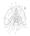
- FIGS. 3 and 4 are sections on the plane III of FIG. 1 , showing the attachment device belonging to the prosthesis during the process of implantation, and the prosthesis after it has been implanted in the shoulder blade, respectively;
- FIG. 5 is an elevation of another embodiment of a shoulder prosthesis, according to some embodiments.
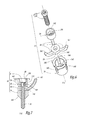
- FIG. 6 is an exploded perspective view of another attachment device, according to some embodiments.
- FIG. 7 is a longitudinal section through the device of FIG. 6 , in the assembled state.
- FIG. 8 is a schematic view of another attachment device, according to some embodiments.
- FIGS. 1 to 4 depict a shoulder prosthesis 1 adapted to be implanted in a shoulder blade S of a human being according to some embodiments, although application in other joints and/or other types of animals are contemplated.
- the prosthesis 1 comprises a glenoid joint component 2 which, after it has been attached to the glenoid cavity G of the shoulder blade S by a device 3 detailed hereinafter, is able to form a joint with a head, possibly a prosthetic head, of the humerus (not depicted) of the patient undergoing surgery so as to reproduce a joint behavior emulating natural shoulder joint behavior.
- the glenoid joint component 2 comprises a base 21 and a pad 22 according to some embodiments.
- the base is generally made of metal and the pad of a polymeric material (e.g., polyethylene), although a variety of other materials and material combinations (e.g., ceramics) are contemplated.
- one side of the pad 22 is firmly attached to the base 21 (e.g., using mechanical fasteners and/or chemical bonds) and an opposite side of the pad 22 defines a concave face 22 A shaped to form a joint with a complementary joint face define by a humeral head (including prosthetic or bone humeral heads) of the patient undergoing surgery.
- a humeral head including prosthetic or bone humeral heads
- the device 3 is designed to anchor the glenoid joint component 2 to the vault V of the glenoid cavity G.
- the vault V is an anatomical bony structure made up of cortical bone matter.
- the cortical bone matter is relatively harder and mechanically stronger bone matter (e.g., in comparison to cancellous bone) having an internal geometry that widens towards the humerus and being centered on the whole on a geometric axis of revolution V.sub.1.
- the vault V is made up of a closed end V.sub.2 extended by a peripheral wall V.sub.3 of which the internal face V.sub.4 is more or less centered on the axis V.sub.1, widening gradually from the closed end V.sub.2 as far as a border of a free end V.sub.5 of the vault V.
- the attachment device 3 comprises a tubular elongate body 4 and a plurality of contact arms 6 .
- the body 4 is substantially cylindrical and centered on an axis X-X, also described as a central longitudinal axis, the body 4 having an exterior face 4 A centered on the axis X-X.
- the body 4 has first and second longitudinal ends 41 , 42 and is sized to be housed in the internal volume of the vault V, including in the fossa F of the glenoid cavity G or glenoid fossa.
- the body 4 is optionally placed in the fossa F, extending lengthwise in such a way that the first longitudinal end 41 lies near the closed end V.sub.2 of the vault V while the second longitudinal end 42 is situated substantially at the same level, along the axis V.sub.1, of the free end V.sub.5 of the vault, as shown in FIGS. 3 and 4 .
- the exterior face 4 A of the body 4 and the internal face V.sub.4 of the vault V define an empty space E between them which extends peripherally around the body 4 , as shown in FIG. 3 .
- the first end 41 of the body 4 is designed to be firmly attached to the closed end V.sub.2 of the vault V by a screw 5 having a shank 51 and a head 52 , or other suitable fastening means.
- the first end 41 of the body 4 is designed to accommodate the screw 5 , centered on the axis X-X, with a portion of the shank 51 of the screw 5 extending through the first end 41 of the body 4 and the remainder of the shank 51 projecting axially from the first end 41 of the body 4 .
- the head 52 of the screw 5 lies inside the body 4 , resting axially against a complementary internal shoulder 43 of the body 4 , as shown in FIG. 3 .
- the second end 42 of the body 4 is adapted to be fixedly attached to the glenoid joint component 2 .
- the second end 42 defines a receptacle with a substantially frustoconical interior surface 44 , centered on the axis X-X and converging toward the first end 41 .
- the surface 44 is shaped to accept, in a complementary manner, a frustoconical peg 23 which projects from the face 21 A of the base 21 that is opposite the pad 22 .
- the base 21 and, thus, the entire component 2 is immobilized relative to the body 4 as shown in FIGS. 1, 2 and 4 .
- the plurality of contact arms 6 are formed as a single unitary piece with the body. As shown, each of the arms 6 projects from the exterior face 4 A of the body 4 at the body end 41 . The arms 6 each extend lengthwise along the body 4 , radially diverging from the axis X-X gradually, starting from the exterior face 4 A as far as each of the free ends 61 . As shown in FIGS. 1 and 2 , each arm 6 has a generally curved longitudinal profile, bulging or splaying out from the body 4 .
- each arm 6 thus, on its opposite side to the body 4 , has a convex surface 62 which, as explained in greater detail, is shaped to rest in a substantially complementary manner against the internal face V.sub.4 of the wall V.sub.3 of the vault V when the body 4 is housed in the fossa F as shown in FIGS. 3 and 4 .
- each arm 6 has a substantially square transverse cross section or profile.
- each arm is substantially rod like, or cylindrical with a circular cross-section.
- the surface 62 is shaped similarly to a portion of a cylinder centered on an axis substantially orthoradial to the axis X-X.
- the four arms 6 are distributed about the body 4 , unevenly here, so as to define, between two successive arms 6 around the body 4 , an empty passage 63 which runs along the entire length of the exterior face 4 A of the body 4 , extending between the edges of the first and second ends 41 , 42 .
- a surgeon opens access to soft tissue surrounding the glenoid cavity G of the shoulder blade S of a patient, in order to access the vault V and the fossa F, as shown in FIG. 1 . If appropriate, the surgeon removes all or some of any remaining spongy bony matter situated in the fossa F, so as to clear access to the internal face V.sub.4 of the peripheral wall V.sub.3 of the vault V.
- the surgeon manipulates the device 3 into position.
- the surgeon introduces the body 4 into the fossa F, substantially aligning the axes X-X and V.sub.1, until the body is positioned, e.g., as shown FIG. 3 .
- the arms 6 are thereby positioned or housed in the fossa F, with the surface 62 of the arms 6 resting against the face V.sub.4 of the wall V.sub.3 of the vault V.
- the convex geometry of the contact surfaces 62 is such that the surfaces 62 hug the face V.sub.4 of the vault V, extending between the end border V.sub.5 and the periphery of the closed end V.sub.2 of the vault V.
- the material connecting each of the arms 6 and the body 4 may have a certain capacity for flexible, or elastic deformation, so as to encourage the spatial adaptation of these arms to the vault V.
- the surgeon optionally adjusts an angular position of the body 4 about the axis X-X to maximize an area of contact between the various contact surfaces 62 and the peripheral wall V.sub.3 of the vault V.
- the arms 6 are distributed unevenly about the body 4 to better suit the non-circular interior profile of the glenoid vault V.
- the screw 5 is introduced into the body 4 from the end 42 such that the shank 51 projects axially from the shank end 41 and the projecting portion of the shank 51 is screwed into the bony matter of which the closed end V.sub.2 of the vault V is formed.
- This screwing into the bone combined with the fact that the head 52 of the screw 5 is resting against the shoulder 43 of the body 4 facilitates, firstly, a primary attachment of the device 3 in relation to the glenoid cavity G and, secondly, the surfaces 62 of the arms 6 to be pressed firmly against the wall V.sub.3 of the vault V.
- the device 3 thus finds itself firmly immobilized in relation to the glenoid cavity G, while at the same time being positioned such that it is centered on the axis V.sub.1 of the vault V (e.g., even if the glenoid cavity is locally worn). In some embodiments, the device 3 is then in the configuration depicted in FIG. 3 .
- the surgeon in a third phase of the surgical procedure, the surgeon introduces a spongy bone graft 7 into the fossa F.
- the graft 7 is of a consistency that is malleable enough that it can be placed all around the body 4 , particularly in the empty passages 63 between the arms 6 such that the graft 7 is able to reach the region of the closed end V.sub.2 of the vault V as desired.
- the empty peripheral space E between the body 4 and the wall V.sub.3 of the vault V is thus filled with the graft 7 as depicted in FIG. 4 .
- the presence of the graft 7 helps improve secondary attachment of the device 3 to the glenoid cavity G.
- the surgeon attaches the glenoid joint component 2 to the device 3 and fixedly connects it to the body 4 , by fitting the peg 23 frustoconically into the end of the shank 42 as shown in FIG. 4 .
- the shoulder prosthesis 1 in use, is mechanically loaded by the head of the humerus associated with the shoulder blade S.
- the arrows 6 in FIG. 4 indicate the means by which the component 2 transmits mechanical stress from the body 4 to the vault V, and in particular the peripheral wall V.sub.3 through the pressing surfaces 62 .
- the mechanical stress is spread over a large contact area and is borne by a cortical structural part of the glenoid cavity G, making the attachment of the component 2 particularly strong. In other words, risk of the component becoming detached is reduced or is otherwise substantially prevented according to some embodiments.
- the body 4 and/or the face 22 A of the component 2 are adapted, or otherwise sized and shaped, to keep the peripheral region of the face 21 A pressed only lightly against the free end border V.sub.5 of the vault V, or even at a distance from the border as depicted in FIG. 4 .
- such an arrangement is not detrimental to the mechanical integrity of the prosthesis 1 because the arms 6 provide sufficient structural attachment to anchor the prosthesis firmly in relation to the glenoid cavity G.
- FIG. 5 shows another shoulder prosthesis 1 ′ including a component 2 ′ and the device 3 .
- the shoulder prosthesis 1 ′ optionally is characterized as a reverse shoulder prosthesis intended to collaborate with a prosthetic humeral component with a concave joint face that complements the face 22 A′.
- the component 2 with a concave joint face 22 A is replaced by a component 2 ′ having a joint face 22 A′ which is convex and an opposite face 21 A′ that is functionally analogous to the face 21 A of the component 2 .
- the face 21 A′ is optionally configured to facilitate fixedly attaching the component 2 ′ to the attachment device 3 via a substantially frustoconical fitting, such as the peg 23 of the device 2 .
- FIGS. 6 and 7 show another device 13 similar to the device 3 .
- the device 13 differs from the device 3 in that the device 3 has fewer arms 16 and/or the arms 16 are not made as one piece with its tubular body 14 , the arms 16 being otherwise secured to the body 14 .
- the device 13 includes three arms 16 borne by a support ring 18 , also described as a support member, the support ring 18 being a separate piece from the body 14 .
- the arms 16 are optionally formed as an integral part of the ring 18 such that the ring 18 joins together the ends of the arms 16 the free ends 161 of the arms 16 .
- the ring 18 is optionally sized to be attached inside the body 14 , being centered on the axis X-X of the body, as depicted in FIG. 7 .
- the ring 18 is adapted to be introduced into the body 14 , from an axial end 142 of the body 14 which is opposite to the end 141 that faces towards the closed end V.sub.2 of the vault V.
- the body 14 in order to allow the ring 18 to fit into the body 14 until it rests axially against an internal shoulder 143 of the body 14 , the body 14 defines straight through-slots 145 , parallel to the axis X-X, each through-slot 145 being shaped to accommodate a corresponding one of the arms 16 .
- Each slot 145 extends from the shoulder 143 as far as the end 142 of the body 14 such that each slot defines an open end opposite the shoulder 143 .
- the device 13 comprises a sleeve 19 designed to be attached coaxially inside the body 14 , more specifically inside the end 142 thereof, with the ring 18 axially interposed between the sleeve 19 and the shoulder 143 , as depicted in FIG. 7 .
- the bore of the sleeve 19 defines a shoulder 191 towards an end of the sleeve that abuts the ring 18 .
- the head 52 of the screw 5 abuts the shoulder 191 , or rests axially against the shoulder 191 , as shown in FIG. 7 .
- the bore forms a frustoconical surface 192 which, when the sleeve 19 is assembled with the body 14 , is centered on the axis X-X and converges towards the end 141 of the body 14 .
- the shoulder 191 and the frustoconical surface 192 function analogously to the shoulder 43 and to the frustoconical surface 44 of the attachment device 3 , with respect to the screw 5 and to the glenoid joint component 2 or 2 ′, respectively.
- Some methods of attaching the component 2 or 2 ′ to the glenoid cavity G proceed as follows. Having opened access to the vault V of the glenoid cavity G, the surgeon introduces the body 14 into the fossa F, more or less aligning the axes X-X and V.sub.1, if necessary until the end 141 of the body is resting against the closed end V.sub.2 of the vault V. The surgeon then introduces the ring 18 , the sleeve 19 and the screw 5 in turn into the interior of the body 14 , passing them through the body end 142 . Progression from the ring 18 as far as the shoulder 143 optionally entails fitting each of the arms 16 into one of the slots 145 . To make the relative angular positioning of the body 14 and the ring 18 easier, the end 142 of the body is advantageously provided with visual identification protrusions 146 .
- screwing the shank 51 of the screw 5 into the bony matter of which the closed end V.sub.2 of the vault V is formed fixes the assembly of the various components of the device 13 while at the same time providing the primary attachment of the device 13 in relation to the glenoid cavity G and pressing the opposite surfaces 162 of the arms 16 to the body 14 against the wall V.sub.3 of the vault V.
- the ring 18 and the sleeve 19 are be added into the body 14 before the body 14 is introduced into the fossa F.
- the fitting of a shoulder prosthesis comprising the component 2 or 2 ′ and the device 13 is completed by next attaching the glenoid joint component 2 or 2 ′ to the device 13 using the frustoconical insertion in the sleeve 19 . If appropriate, the first and third phases of the surgical procedure previously mentioned are implemented as desired during fitting.
- the arms 6 or 16 are respectively connected to the body 4 or to the ring 18 by articulated mechanical means designed to allow each arm to pivot with respect to the body about an axis of articulation that is orthoradial to the axis X-X.
- the pivoting of the arms 6 or 16 about the aforementioned axes is then advantageously brought about by the screw 5 when the latter is introduced through the end 41 or 141 of the body 4 or 14 to be screwed into the closed end V.sub.2 of the vault V.
- the force with which the arms 6 or 16 are anchored in relation to the glenoid cavity G are adjusted as desired by the surgeon using the screw 5 .
- FIG. 8 shows another device 23 including a body 24 , a screw 25 , arms 26 , and a sleeve 219 , where the arms 26 articulate mechanically upon turning of screw 25 .
- the arms 26 are pivotably engaged with the body 25 and a sleeve 219 .
- the sleeve 219 is engaged with the screw 25 such that the sleeve 219 moves axially along the screw 25 upon turning the screw 25 .
- the arms 26 are thereby optionally deployed using the screw 25 according to some embodiments.
- the body 4 or 14 and the arms 6 or 16 and, where appropriate, the ring 18 and the sleeve 19 are made of materials that are able to withstand the mechanical stresses described above while at the same time affording a lasting connection between them that is either rigid or elastically deformable or articulated as mentioned previously.
- they may be made of metal or a polymer, it being pointed out moreover that the materials of which the body 4 and the arms 6 are respectively made optionally have different compositions. Where use is made of a polymer, the latter is advantageously bioresorbable.
- the latter may advantageously be a shape memory alloy, for example, making it possible, when the body 4 or 14 is being placed inside the fossa F, for the curved longitudinal profile of the arms 6 to be modified through a shape memory effect in order to strengthen the anchorage of the device 3 or 13 in relation to the glenoid cavity G.
- the material chosen from which to make the body 4 or 14 and the arms 6 or 16 is advantageously porous, to encourage the secondary attachment by bone regrowth. Furthermore, the bone regrowth is also encouraged by ensuring that the body and the arms have a holed solid structure encouraging biological exchanges within the fossa F as previously described.
- the end 42 of the body 4 or the sleeve 19 and the face 22 A or 22 A′ of the glenoid joint component 2 or 2 ′ are optionally fixably attached together by different complementing shapes, such as a dovetail shape.
- a fastener is optionally added between the components, such as a screw.
- the cross section of the arms 6 or 16 may have an exterior outline of a shape other than that of a square, provided that, on the opposite side to the body 4 or 14 , each arm 6 or 16 has a surface for resting against the internal face V.sub.4 of the wall V.sub.3 of the vault V adapted to contact the vault V, e.g., analogously to the contact surfaces 62 or 162 described above.
- each of these contact surfaces has, particularly in the longitudinal direction of the arm 6 or 16 , a profile involving teeth and troughs to improve the purchase of the surface on the wall V.sub.3 of the vault V.
- the number of arms 6 or 16 is not limited to four or three, it being understood that, for reasons of stability, generally three or more arms are contemplated to ensure three separate contact regions (e.g., five or more arms are possible). Additionally, the screw 5 for fastening into the bone may be replaced by any analogous fastening means able to collaborate with the end 41 or 141 of the body 4 or 14 .
Landscapes
- Health & Medical Sciences (AREA)
- Orthopedic Medicine & Surgery (AREA)
- Cardiology (AREA)
- Oral & Maxillofacial Surgery (AREA)
- Transplantation (AREA)
- Engineering & Computer Science (AREA)
- Biomedical Technology (AREA)
- Heart & Thoracic Surgery (AREA)
- Vascular Medicine (AREA)
- Life Sciences & Earth Sciences (AREA)
- Animal Behavior & Ethology (AREA)
- General Health & Medical Sciences (AREA)
- Public Health (AREA)
- Veterinary Medicine (AREA)
- Prostheses (AREA)
Abstract
Description
Claims (19)
Priority Applications (1)
| Application Number | Priority Date | Filing Date | Title |
|---|---|---|---|
| US14/511,967 US9655732B2 (en) | 2009-04-22 | 2014-10-10 | Joint prosthesis attachment system, device and method |
Applications Claiming Priority (4)
| Application Number | Priority Date | Filing Date | Title |
|---|---|---|---|
| FR952635 | 2009-04-22 | ||
| FR0952635A FR2944694B1 (en) | 2009-04-22 | 2009-04-22 | DEVICE FOR FIXING THE GLENE OF A GLENOIDAL ARTICULAR COMPONENT FOR A SHOULDER PROSTHESIS AND CORRESPONDING SHOULDER PROSTHESIS |
| US12/765,347 US8858640B2 (en) | 2009-04-22 | 2010-04-22 | Joint prosthesis attachment system, device and method |
| US14/511,967 US9655732B2 (en) | 2009-04-22 | 2014-10-10 | Joint prosthesis attachment system, device and method |
Related Parent Applications (1)
| Application Number | Title | Priority Date | Filing Date |
|---|---|---|---|
| US12/765,347 Division US8858640B2 (en) | 2009-04-22 | 2010-04-22 | Joint prosthesis attachment system, device and method |
Publications (2)
| Publication Number | Publication Date |
|---|---|
| US20150032214A1 US20150032214A1 (en) | 2015-01-29 |
| US9655732B2 true US9655732B2 (en) | 2017-05-23 |
Family
ID=41227303
Family Applications (2)
| Application Number | Title | Priority Date | Filing Date |
|---|---|---|---|
| US12/765,347 Active 2030-08-05 US8858640B2 (en) | 2009-04-22 | 2010-04-22 | Joint prosthesis attachment system, device and method |
| US14/511,967 Expired - Fee Related US9655732B2 (en) | 2009-04-22 | 2014-10-10 | Joint prosthesis attachment system, device and method |
Family Applications Before (1)
| Application Number | Title | Priority Date | Filing Date |
|---|---|---|---|
| US12/765,347 Active 2030-08-05 US8858640B2 (en) | 2009-04-22 | 2010-04-22 | Joint prosthesis attachment system, device and method |
Country Status (3)
| Country | Link |
|---|---|
| US (2) | US8858640B2 (en) |
| EP (1) | EP2243444B1 (en) |
| FR (1) | FR2944694B1 (en) |
Families Citing this family (45)
| Publication number | Priority date | Publication date | Assignee | Title |
|---|---|---|---|---|
| US8632597B2 (en) | 2008-12-23 | 2014-01-21 | DePuy Synthes Products, LLC | Rotatable reverse metaglene |
| FR2944694B1 (en) | 2009-04-22 | 2012-05-18 | Tornier Sa | DEVICE FOR FIXING THE GLENE OF A GLENOIDAL ARTICULAR COMPONENT FOR A SHOULDER PROSTHESIS AND CORRESPONDING SHOULDER PROSTHESIS |
| FR2955247B1 (en) | 2010-01-21 | 2013-04-26 | Tornier Sa | GLENOIDAL COMPONENT OF SHOULDER PROSTHESIS |
| BR112012030045A2 (en) | 2010-05-26 | 2016-08-09 | Topsfield Medical Gmbh | implantable prostheses |
| US8454702B2 (en) * | 2011-01-20 | 2013-06-04 | Biomet Manufacturing Corp. | Reverse shoulder prosthetic |
| FR2971144A1 (en) | 2011-02-08 | 2012-08-10 | Tornier Sa | GLENOIDAL IMPLANT FOR SHOULDER PROSTHESIS AND SURGICAL KIT |
| WO2012125704A2 (en) * | 2011-03-14 | 2012-09-20 | Topsfield Medical Gmbh | Implantable glenoid prostheses |
| US9820758B2 (en) | 2011-03-18 | 2017-11-21 | DePuy Synthes Products, Inc. | Combination reamer/drill bit for shoulder arthoplasty |
| US9226830B2 (en) | 2011-03-18 | 2016-01-05 | DePuy Synthes Products, Inc. | Device and method for retroversion correction for shoulder arthroplasty |
| US8764836B2 (en) | 2011-03-18 | 2014-07-01 | Lieven de Wilde | Circular glenoid method for shoulder arthroplasty |
| US9763679B2 (en) | 2011-03-18 | 2017-09-19 | DePuy Synthes Products, Inc. | Combination driver/anti-rotation handle for shoulder arthroplasty |
| US8551177B2 (en) * | 2011-03-18 | 2013-10-08 | DePuy Synthes Products, LLC | Revision glenoid kit |
| US20130018476A1 (en) | 2011-07-13 | 2013-01-17 | Biomet Manufacturing Corp. | Shoulder prosthesis |
| US8506638B2 (en) * | 2011-07-13 | 2013-08-13 | Biomets Manufacturing, LLC | Shoulder prosthesis |
| US8449617B1 (en) * | 2011-11-16 | 2013-05-28 | Biomet Manufacturing Corp. | Convertible glenoid implant |
| US9439768B2 (en) | 2011-12-08 | 2016-09-13 | Imds Llc | Glenoid vault fixation |
| US9414927B2 (en) | 2011-12-08 | 2016-08-16 | Imds Llc | Shoulder arthroplasty |
| EP3005987B1 (en) * | 2012-05-10 | 2017-07-19 | DePuy Synthes Products, LLC | Rotatable reverse metaglene assembly |
| WO2014005644A1 (en) * | 2012-07-05 | 2014-01-09 | Limacorporate S.P.A. | Humeral implant for a shoulder prosthesis |
| US9788957B2 (en) | 2012-12-07 | 2017-10-17 | Cleveland Clinic Foundation | Glenoid vault fixation |
| US9668873B2 (en) | 2013-03-08 | 2017-06-06 | Biomet Manufacturing, Llc | Modular glenoid base plate with augments |
| EP2967893B1 (en) | 2013-03-15 | 2017-03-01 | The Cleveland Clinic Foundation | Prosthetic articulation surface mounting |
| US9962266B2 (en) | 2015-09-11 | 2018-05-08 | Deltoid, Llc | Arthroplasty components |
| US10433969B2 (en) | 2013-12-30 | 2019-10-08 | United Orthopedic Corp. | Arthroplasty implants and methods for orienting joint prosthesis |
| EP3777777B1 (en) | 2014-01-03 | 2023-04-05 | Howmedica Osteonics Corp. | Glenoid implant for a shoulder prosthesis |
| US10456264B2 (en) * | 2014-01-24 | 2019-10-29 | Tornier, Inc. | Humeral implant anchor system |
| US12023253B2 (en) * | 2014-01-24 | 2024-07-02 | Howmedica Osteonics Corp. | Humeral implant anchor system |
| US9681960B2 (en) | 2014-05-16 | 2017-06-20 | Howmedica Osteonics Corp. | Guides for fracture system |
| US10575968B2 (en) | 2014-05-16 | 2020-03-03 | Howmedica Osteonics Corp. | Guides for fracture system |
| US10722374B2 (en) * | 2015-05-05 | 2020-07-28 | Tornier, Inc. | Convertible glenoid implant |
| USD835276S1 (en) | 2015-09-11 | 2018-12-04 | United Orthopedic Corporation | Keeled glenoid |
| EP3435915B1 (en) * | 2017-03-24 | 2023-01-18 | Mayo Foundation for Medical Education and Research | Joint arthroplasty component design |
| PL3644906T3 (en) | 2017-06-29 | 2022-06-13 | Encore Medical, L.P. (D/B/A Djo Surgical) | Glenosphere with inserts for augmented fixation |
| WO2019079104A2 (en) | 2017-10-16 | 2019-04-25 | Imascap Sas | Shoulder implants and methods of use and assembly |
| US11399948B2 (en) | 2017-12-11 | 2022-08-02 | Howmedica Osteonics Corp. | Stemless prosthesis anchor components and kits |
| WO2020072452A1 (en) | 2018-10-02 | 2020-04-09 | Tornier, Inc. | Shoulder prosthesis components and assemblies |
| CN109925099B (en) * | 2019-04-17 | 2024-03-29 | 嘉思特医疗器材(天津)股份有限公司 | Biological knee joint mechanical locking structure tibia platform |
| AU2020262482B2 (en) * | 2019-04-25 | 2025-11-20 | Encore Medical, L.P. (D/B/A Djo Surgical) | Glenoid implant |
| EP3968905A1 (en) | 2019-05-13 | 2022-03-23 | Howmedica Osteonics Corp. | Glenoid baseplate and implant assemblies |
| AU2020204539B2 (en) * | 2019-07-12 | 2024-10-31 | Howmedica Osteonics Corp. | Augmented glenoid design |
| WO2021030146A1 (en) | 2019-08-09 | 2021-02-18 | Tornier, Inc. | Apparatuses and methods for implanting glenoid prostheses |
| US12370051B2 (en) | 2019-10-01 | 2025-07-29 | Howmedica Osteonics Corp. | Shoulder prosthesis components and assemblies |
| USD951449S1 (en) | 2019-10-01 | 2022-05-10 | Howmedica Osteonics Corp. | Humeral implant |
| US11850158B2 (en) * | 2020-05-26 | 2023-12-26 | Howmedica Osteonics Corp. | Orthopedic surgical implant device with porous material and fluid channels for cleaning the porous material |
| EP4271291A4 (en) | 2021-02-26 | 2024-11-27 | Howmedica Osteonics Corp. | Glenoid implant components and instruments therefor |
Citations (11)
| Publication number | Priority date | Publication date | Assignee | Title |
|---|---|---|---|---|
| US5593448A (en) | 1995-11-14 | 1997-01-14 | Osteonics Corp. | Glenoid component for shoulder prosthesis and implant method |
| US5658341A (en) | 1993-03-10 | 1997-08-19 | Medinov S.A. | Tibial implant for a knee prosthesis |
| US5800551A (en) | 1997-03-10 | 1998-09-01 | Biomet, Inc. | Apparatus and method for shoulder arthroplasty |
| US20030055507A1 (en) | 2001-09-11 | 2003-03-20 | Incumed, Incorporated | Modular prosthesis and insertion tool for bone structures |
| EP1402853A2 (en) | 2002-09-27 | 2004-03-31 | Depuy Products, Inc. | Concave resurfacing glenoid prosthesis |
| US20050261775A1 (en) | 2004-05-19 | 2005-11-24 | Zimmer Gmbh | Glenoid anchor |
| EP1639967A1 (en) | 2004-09-27 | 2006-03-29 | DePuy Products, Inc. | Modular glenoid prosthesis |
| US20070150065A1 (en) * | 2005-11-07 | 2007-06-28 | Laurent Angibaud | Mounting system and method for enhancing implant fixation to bone |
| US20070260321A1 (en) | 2006-05-02 | 2007-11-08 | Stchur Robert P | Conically-shaped glenoid implant with a prosthetic glenoid insert used in total shoulder arthroplasty and method |
| US20100114326A1 (en) | 2008-10-30 | 2010-05-06 | Biomet Manufacturing Corp. | Modular implant for joint prosthesis |
| US20100274359A1 (en) | 2009-04-22 | 2010-10-28 | Yann Brunnarius | Joint prosthesis attachment system, device and method |
-
2009
- 2009-04-22 FR FR0952635A patent/FR2944694B1/en active Active
-
2010
- 2010-04-20 EP EP10160400A patent/EP2243444B1/en active Active
- 2010-04-22 US US12/765,347 patent/US8858640B2/en active Active
-
2014
- 2014-10-10 US US14/511,967 patent/US9655732B2/en not_active Expired - Fee Related
Patent Citations (14)
| Publication number | Priority date | Publication date | Assignee | Title |
|---|---|---|---|---|
| US5658341A (en) | 1993-03-10 | 1997-08-19 | Medinov S.A. | Tibial implant for a knee prosthesis |
| US5593448A (en) | 1995-11-14 | 1997-01-14 | Osteonics Corp. | Glenoid component for shoulder prosthesis and implant method |
| US5800551A (en) | 1997-03-10 | 1998-09-01 | Biomet, Inc. | Apparatus and method for shoulder arthroplasty |
| US20030055507A1 (en) | 2001-09-11 | 2003-03-20 | Incumed, Incorporated | Modular prosthesis and insertion tool for bone structures |
| EP1402853B1 (en) | 2002-09-27 | 2010-05-19 | Depuy Products, Inc. | Concave resurfacing glenoid prosthesis with dome-shaped stem |
| EP1402853A2 (en) | 2002-09-27 | 2004-03-31 | Depuy Products, Inc. | Concave resurfacing glenoid prosthesis |
| US20050261775A1 (en) | 2004-05-19 | 2005-11-24 | Zimmer Gmbh | Glenoid anchor |
| EP1639967A1 (en) | 2004-09-27 | 2006-03-29 | DePuy Products, Inc. | Modular glenoid prosthesis |
| EP1639967B1 (en) | 2004-09-27 | 2008-07-02 | DePuy Products, Inc. | Modular glenoid prosthesis |
| US20070150065A1 (en) * | 2005-11-07 | 2007-06-28 | Laurent Angibaud | Mounting system and method for enhancing implant fixation to bone |
| US20070260321A1 (en) | 2006-05-02 | 2007-11-08 | Stchur Robert P | Conically-shaped glenoid implant with a prosthetic glenoid insert used in total shoulder arthroplasty and method |
| US20100114326A1 (en) | 2008-10-30 | 2010-05-06 | Biomet Manufacturing Corp. | Modular implant for joint prosthesis |
| US20100274359A1 (en) | 2009-04-22 | 2010-10-28 | Yann Brunnarius | Joint prosthesis attachment system, device and method |
| US8858640B2 (en) | 2009-04-22 | 2014-10-14 | Biomet France Sarl | Joint prosthesis attachment system, device and method |
Non-Patent Citations (13)
Also Published As
| Publication number | Publication date |
|---|---|
| US20150032214A1 (en) | 2015-01-29 |
| EP2243444A1 (en) | 2010-10-27 |
| US8858640B2 (en) | 2014-10-14 |
| FR2944694B1 (en) | 2012-05-18 |
| FR2944694A1 (en) | 2010-10-29 |
| US20100274359A1 (en) | 2010-10-28 |
| EP2243444B1 (en) | 2013-01-02 |
Similar Documents
| Publication | Publication Date | Title |
|---|---|---|
| US9655732B2 (en) | Joint prosthesis attachment system, device and method | |
| US9283083B2 (en) | Shoulder implant assembly | |
| US7585327B2 (en) | Extended articular surface resurfacing head | |
| US8062376B2 (en) | Shoulder implant assembly | |
| US7338528B2 (en) | Humeral stem with anatomical location of taper access for fixation of humeral head | |
| US4728335A (en) | Hip prosthesis | |
| US4865605A (en) | Modular shoulder prosthesis | |
| US6458161B1 (en) | Method and apparatus for acetabular reconstruction | |
| JP5671106B2 (en) | Method for manufacturing an artificial acetabular external assembly | |
| US8936647B2 (en) | Elbow prosthesis | |
| US10251756B2 (en) | Prosthesis for a shoulder articulation | |
| CN113194885A (en) | Improved glenoid adapter for shoulder joint prosthesis | |
| US7485148B2 (en) | Prosthesis | |
| JP5680632B2 (en) | Prosthesis | |
| US20060079963A1 (en) | Semiconstrained shoulder prosthetic for treatment of rotator cuff arthropathy | |
| EP2564814A1 (en) | Stemless shoulder implant assembly | |
| US20060217815A1 (en) | Modular prosthetic head having a flat portion to be implanted into a constrained liner | |
| US20150289984A1 (en) | Total Shoulder Arthroplasty Prosthesis | |
| US20080208348A1 (en) | Apparatus and Method for Shoulder Arthroplasty | |
| JP2010515532A (en) | Knee joint prosthesis system and implantation method | |
| CA2327199C (en) | Metatarsophalangeal resurfacing joint | |
| JP2024503695A (en) | Reverse shoulder prosthesis and related methods | |
| JP7780642B2 (en) | Stemless implant system for arthroplasty | |
| JP2024508574A (en) | artificial shoulder joint | |
| CA2340158A1 (en) | Joint prosthesis and anchoring means |
Legal Events
| Date | Code | Title | Description |
|---|---|---|---|
| AS | Assignment |
Owner name: BIOMET FRANCE SARL, FRANCE Free format text: ASSIGNMENT OF ASSIGNORS INTEREST;ASSIGNOR:TORNIER SAS;REEL/FRAME:034138/0552 Effective date: 20140116 Owner name: TORNIER SAS, FRANCE Free format text: ASSIGNMENT OF ASSIGNORS INTEREST;ASSIGNORS:BRUNNARIUS, YANN;DERANSART, PIERRIC;SIGNING DATES FROM 20100518 TO 20100526;REEL/FRAME:034138/0505 |
|
| FEPP | Fee payment procedure |
Free format text: PAYOR NUMBER ASSIGNED (ORIGINAL EVENT CODE: ASPN); ENTITY STATUS OF PATENT OWNER: LARGE ENTITY |
|
| STCF | Information on status: patent grant |
Free format text: PATENTED CASE |
|
| MAFP | Maintenance fee payment |
Free format text: PAYMENT OF MAINTENANCE FEE, 4TH YEAR, LARGE ENTITY (ORIGINAL EVENT CODE: M1551); ENTITY STATUS OF PATENT OWNER: LARGE ENTITY Year of fee payment: 4 |
|
| FEPP | Fee payment procedure |
Free format text: MAINTENANCE FEE REMINDER MAILED (ORIGINAL EVENT CODE: REM.); ENTITY STATUS OF PATENT OWNER: LARGE ENTITY |
|
| LAPS | Lapse for failure to pay maintenance fees |
Free format text: PATENT EXPIRED FOR FAILURE TO PAY MAINTENANCE FEES (ORIGINAL EVENT CODE: EXP.); ENTITY STATUS OF PATENT OWNER: LARGE ENTITY |
|
| STCH | Information on status: patent discontinuation |
Free format text: PATENT EXPIRED DUE TO NONPAYMENT OF MAINTENANCE FEES UNDER 37 CFR 1.362 |
|
| FP | Lapsed due to failure to pay maintenance fee |
Effective date: 20250523 |