US965561A - Fabric-piling mechanism. - Google Patents
Fabric-piling mechanism. Download PDFInfo
- Publication number
- US965561A US965561A US47658009A US1909476580A US965561A US 965561 A US965561 A US 965561A US 47658009 A US47658009 A US 47658009A US 1909476580 A US1909476580 A US 1909476580A US 965561 A US965561 A US 965561A
- Authority
- US
- United States
- Prior art keywords
- fabric
- shaft
- chute
- sleeve
- clutch
- Prior art date
- Legal status (The legal status is an assumption and is not a legal conclusion. Google has not performed a legal analysis and makes no representation as to the accuracy of the status listed.)
- Expired - Lifetime
Links
- 230000007246 mechanism Effects 0.000 title description 25
- 239000004744 fabric Substances 0.000 description 53
- 230000000694 effects Effects 0.000 description 7
- 238000000034 method Methods 0.000 description 3
- 230000008569 process Effects 0.000 description 3
- 230000008859 change Effects 0.000 description 2
- 238000010276 construction Methods 0.000 description 2
- 230000009471 action Effects 0.000 description 1
- 239000011230 binding agent Substances 0.000 description 1
- 230000006835 compression Effects 0.000 description 1
- 238000007906 compression Methods 0.000 description 1
- 210000005069 ears Anatomy 0.000 description 1
- 238000004519 manufacturing process Methods 0.000 description 1
- 238000009877 rendering Methods 0.000 description 1
- 239000011435 rock Substances 0.000 description 1
Images


Classifications
-
- B—PERFORMING OPERATIONS; TRANSPORTING
- B65—CONVEYING; PACKING; STORING; HANDLING THIN OR FILAMENTARY MATERIAL
- B65H—HANDLING THIN OR FILAMENTARY MATERIAL, e.g. SHEETS, WEBS, CABLES
- B65H54/00—Winding, coiling, or depositing filamentary material
- B65H54/02—Winding and traversing material on to reels, bobbins, tubes, or like package cores or formers
- B65H54/28—Traversing devices; Package-shaping arrangements
-
- B—PERFORMING OPERATIONS; TRANSPORTING
- B65—CONVEYING; PACKING; STORING; HANDLING THIN OR FILAMENTARY MATERIAL
- B65H—HANDLING THIN OR FILAMENTARY MATERIAL, e.g. SHEETS, WEBS, CABLES
- B65H2701/00—Handled material; Storage means
- B65H2701/30—Handled filamentary material
- B65H2701/31—Textiles threads or artificial strands of filaments
Definitions
- This invention has reference to improvements in machines whereby fabric, received from a prior process or from a step in such process, may be arranged in a pile, for convenience in transporting a mass of such fabric, 01' to facilitate the subjection of said fabric to a subsequent step in the process of its manufacture.
- Another object of the invention is to construct a fabric piling machine of this nature that the same may be operated at comparatively high speed.
- FIG. 3 represents a sectional view of parts of the clutch mechanism taken on line 3-3 Fig. 2.
- F1g. 4 represents a sectional view, taken on line 4-4 Fig. 6, illustrating the clutch connections for changing the direction of movement of the lap delivering device.
- Fig. 5 represents a sectional view of said clutch mechanism taken on line 4-4 Fig. 6, with the shaft 61 and the attendant mechanisms removed.
- Fig. 6, represents a simllar view fabric, approximately as arranged by the machine under consideration.
- FIG. 10 represents a supporting frame work of any suitable nature preferably having the depending members 12-12 which supportcross members 13 and 14.
- brackets 17-17 and 18-18 having bearings in which are journaled, the shafts 19-19 and 20-20 having respectively the inwardly projecting arms 21-21 and 22-22, and the upright arms 23-24 and 25-26 of which arms 23 and 24 are connected by the link 27 while arms 25 and 26 are connected by link 28 so that when the arms 24 and 26 are swung, by the action of their respective levers 29 and 30, motion is transmitted to all of said shafts 17-17 and 18-18 to swing the arms 21-21 and 22-22.
- the rods 31-31 and 32-32 Pivotally connected to the arms 21-21 and 22-22 are the rods 31-31 and 32-32 which, at their lower ends, are pivotally con nected with ears 33-33 and 34-34 of the fabric delivery device or guide chute 35 which is herein shown as of rectangular shape in cross section with inclined sides but which obviously are of any suitable shape and size.
- Lever 30 is actuated by rod 36 which is connected with the crank arm 37 of shaft 38 journaled in suitable bearings and having the bevel pinion 39; while lever 29 is actuated through the connecting rod 40.
- Automatic change gear driving mechanism is employed to operate the pinion 39 and the connecting rod 40 at relative speeds, as follows: End frames 41 and 42, having suitable bearings, are connected by the cross braces 43 and 44. In bearings located on said frames is journaled the drive shaft 45 having the drive pulley 46, adapted to be driven in any usual manner, and the pinion 47 and the large gear 48 both fixed on said shaft 45 of which the former is engaged with pinion 49 rotatably mounted on a stud extending from frame 42 and meshing with the large gear 50 mounted on the clutch sleeve 51 which is rotatable on shaft 52 journaled in bearings in the frames 41 and 42 and having at one end the bevel pinion 53 in engagement with pinion 39.
- Gear 48 meshes with idle pinion 54, rotatable on a stud extending from frame 41, which meshes with small gear 55 of the clutch sleeve 56 journaled on said shaft 52.
- Slidably mounted on the shaft 52 is the double clutch connecting sleeve 57 which is adapted to be shifted by means of the bell crank lever 58, pivotally mounted on a pin extending from brace 44, whereby said clutch connector 57 may engage with either of the clutch sleeves 51 or 56 to connect either of said sleeves with said shaft 52 in order to drive said shaft from the shaft 45 at a low speed, if such connection is through pinions 47-49 and gear 50 or at comparatively a high speed if such connection is made through large gear 48 and pinions 54 and 55.
- journaled in bearings of the frames 41 and 42 is the shaft 60 having the enlarged diameter 61 and furnished at one end with the crank arm 62 pivotally connected with the connecting rod 40.
- Rotatable on said shaft 60 is the gear 63, driven from pinions 59 and 47, having affixed thereto a clutch member comprising the sleeve 64, bearing against the shoulder formed by the enlargement 61 of said shaft and having the lip 65 embracing the end portion of said enlargement, and the rim 66 having the annular rib 67 having the inclined cam 68 forming one edge of the opening 69.
- the housing 70 On said shaft 60 is supported the housing 70 having the flange 71 at the lower portion of which is mounted one end of the shaft 72, of which the other end is mounted in frame 41, and journaled on this shaft is the idle pinion 73 which meshes with the large gear 48, and with the pinion 74 of clutch sleeve 75 rotatable on shaft 60 andhaving a shoulder bearing against this end of the enlargement 61, of said shaft, and having the annular lip 76.
- the flange 71 has the pocket 77 formed in its face and on said flange is mounted the casing 78 having the rib 79 extending partially around the interior of said casing whereby the opening 80 is left between the ends of said rib.
- the open end of said casing 78 is partially closed by the annular plate 81 having the pocket 82 in line with the pocket 77 and rotatable in the wall of said casing is the shaft 83 having at its inner end the pawl 84 of which the free end is adapted to be swung into either of said pockets 77 or 82, as the case may be, by the actuation of the arm 85, at the outer end of said shaft 83, through the medium of shift rod 86 having the stud 87 which pivotally engages a slot in said arm 85.
- the shift rod 86 is slidable in a bearing extending from flange 71, see Fig.
- the fabric u-a in rope form is carried to this machine by any suitable means as by the pulley p usually employed to guide or move fabric in bleacheries or similar manufactories.
- the pile of fabric may be formed as above described in a suitable vat or keir, in which the piled fabric may be chemically treated, or said pile may be formed on a truck on which the fabric may be transported from the location of the piling mechanism to some other point for treatment or for storage.
- the fabric a-a passing through the upper portion of the delivery chute defines, approximately, a fixed vertical line or axis with reference to which the vibratory movements of the delivery chute are relative, while the swinging of said delivery device is about the axis defined by the pivots on which the chute swings. Both movements of the single chute 35 are vibratory but the term swing is preferably used 'to indicate the slow movement of said chute.
- a fabric piling machine comprising a fabric delivery device having a fixed point within the end of said device where the fabric enters, said device having a delivery end that is adapted to be vibrated about said fixed point, mechanism acting to swing said device transversely of said fixed point in two directions at different speeds and means for intermittently changing the speed of said device.
- a fabric piling machine comprising a fabric delivery device having a fixed point within the end of said device at which the fabric enters, said device being mounted to be vibrated about said fixed point, mechanism acting to vibrate said device in two directions relatively at right angles and at different speeds, and means for changing respectively said speeds.
- a fabric piling machine comprising a fabric delivery device having a fixed point at the end where the fabric enters said device, and having a delivery end which is adapted to be swung about said fixed point, means for slowly swinging said delivery end of said device in an arc and means for rapidly vibrating said device transversely of said arc.
- a fabric piling machine comprising a fabric delivery chute mounted for swinging movement in a series of directions from a point within said chute, means for slowly moving the delivery end of said chute about said point as a center to carry the cloth in a lateral direction, and means for effecting the rapid vibration of said chute about said oint in a direction transverse to that in which said chute is being moved slowly.
- a fabric piling machine comprising a fabric delivery chute, pairs of pivots located on the delivery chute and upon which said chute may be swung in two directions, movable means for supporting said pivots and means operatively connected with said movable means for vibrating said chute.
- a fabric piling machine comprising a fabric delivery chute, pairs of pivots oppositely disposed with reference to said chute, movable supports for said pairs of pivots, means operatively connected with said movable supports for causing said chute to be vibrated rapidly in one direction and slowly in a direction at right angles to the rapid vibration and means for alternating the relationship of rapid and slow vibration.
- a fabric piling device comprising a fabric delivery chute, pivots attached to said chute, and means for vibrating said chute, the parts being constructed and arranged in such manner that one point in the axis of said chute remains stationary when the chute is vibrated.
- a fabric piling machine comprising a fabric delivery chute, pivotal mountings 0n the delivery chute which are arranged in such manner that said chute may have a vibratory movement in two directions at right angles to each other, the mounting of said chute being such that one point in the axis of said chute remains stationary, and means for vibrating said chute.
- a fabric piling device comprising a chute mounted on pairs of pivots, the axes of said pairs of pivots intersecting, means for vibrating said chute, the arrangement and construction of parts being such that when said delivery chute is vibrated the point of intersection of the axes of the pivotal mounts is stationary, and means for vibrating said chute.
- a fabric piling device including a fabric delivery chute, pivotal mountings on said chute, and means attached to said pivotal mounts adapted to vibrate said chute, the parts being constructed and arranged in such manner that one point in the axis of said chute near the end of the chute where the fabric enters remains stationary when said chute is vibrated.
- a delivery chute pivots upon said chute, means for vibrating the delivery chute, said vibrating means including a driving shaft, two driven shafts, two sets of gearing mechanism and clutch mechanism arranged in such manner as to clutch one set of gearing mechanism with the driving shaft and one driven shaft and the other set of gearing mechanism with the other driven shaft, means for operating said clutch mechanism, means for moving said operative means and mechanism for determining when said operative means shall become effective.
- a delivery chute pivots about which said delivery chute is adapted to vibrate, means for vibrating said delivery chute, said vibrating means comprising a driving shaft, two driven shafts, two sets of gear mechanism and clutch mechanism adapted to connect one driven shaft with the driving shaft through one set of gear mechanism and the other driven shaft with the driving shaft through the other set of gear mechanism, a rotary cam upon one driving shaft, means operated by said rotary cam, means for operating said clutch mechanism, compression such manner that one of said driven shafts rotates faster than the other of said driven shafts, clutch mechanism for determining which of said driven shafts shall be rotated at the higher rate of speed, means for rendering said clutch mechanism operative and means for determining when means shall become effective.
Landscapes
- Transmission Devices (AREA)
Description
J. A. BUTLER.
FABRIC FILING MEGHANISM.
APPLICATION FILED PEB- 6, 1909.
965,561 Patented July 26, 1910.
3 SHEETS-SHEET 1.
ZQiZnesses I 71/216 M20 7 THE NORRIS PETERS c0, wAslgmarcn, n, c
J. A. BUTLER. FABRIC 21mm MECHANISM. 'APPLIOATIOfi FILED P33, 8, 1909.
Patented July 26, 1910.
a SHEETS-SHEET 2.
/9 .lma
[710674/77072' lmwa am M 7.
Zda'iizessea snmarzm, 1:. c,
1n: NORRIS J. A. BUTLER. FABRIC PILING MECHANISM.
APPLIUATION FILED FEB. 6, 1909.
Patented July 26, 1910.
3 SHEETS-:SHEET 3.
[7L z/e n 20 7".-
M A. rwv.
THE NORRIS mzrzg co., wasnmarou, n. c.
(IN 1TB %TATE% PATENT FREE.
FABRIC-FILING MECHANISM.
Specification of Letters Patent.
Patented July 26, 1910.
Application filed February 8, 1909. Serial No. 476,580.
To all whom it may concern:
Be it known that I, JAMES A. BUTLER, of lVinthrop, in the county of Suffolk and State of Massachusetts, have invented certain new and useful Improvements in Fabric- Piling Mechanisms, of which the following is a specification, reference being had to the accompanying drawings, forming part thereof.
This invention has reference to improvements in machines whereby fabric, received from a prior process or from a step in such process, may be arranged in a pile, for convenience in transporting a mass of such fabric, 01' to facilitate the subjection of said fabric to a subsequent step in the process of its manufacture.
One object of the invention is to so construct a machine of this character that fabric, in a ropy form, may be progressively arranged by such machine in a series of superposed layers each formed of transverse laps of fabric with the laps of the respective layers extending approximately at right an gles with the laps of the adjacent layers whereby the successive layers act as binders to give stability to the mass or pile of fabric and preventing the entanglement of the several laps or layers whereby said layers may be drawn off, from said pile, in succession.
Another object of the invention is to construct a fabric piling machine of this nature that the same may be operated at comparatively high speed.
Another object of the invention is to so construct a fabric piling machine that a single lap forming device may operate to fold fabric in laps extending in more than one direction and that the direction in which the laps are laid may intermittently and promptly change.
The invention consists in such peculiar features of construction and combination of parts as shall hereinafter be more fully described and pointed out in the claims.
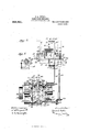
Figure 1, represents a side elevation of the improved fabric plling machme. Flg. 2, represents a plan view of the same. Fig.
3, represents a sectional view of parts of the clutch mechanism taken on line 3-3 Fig. 2. F1g. 4, represents a sectional view, taken on line 4-4 Fig. 6, illustrating the clutch connections for changing the direction of movement of the lap delivering device. Fig. 5, represents a sectional view of said clutch mechanism taken on line 4-4 Fig. 6, with the shaft 61 and the attendant mechanisms removed. Fig. 6, represents a simllar view fabric, approximately as arranged by the machine under consideration.
Similar numbers of reference designate corresponding parts throughout.
As shown in the drawings in its preferred form 10 represents a supporting frame work of any suitable nature preferably having the depending members 12-12 which supportcross members 13 and 14. On the frame 10 are mounted pairs of brackets 17-17 and 18-18 having bearings in which are journaled, the shafts 19-19 and 20-20 having respectively the inwardly projecting arms 21-21 and 22-22, and the upright arms 23-24 and 25-26 of which arms 23 and 24 are connected by the link 27 while arms 25 and 26 are connected by link 28 so that when the arms 24 and 26 are swung, by the action of their respective levers 29 and 30, motion is transmitted to all of said shafts 17-17 and 18-18 to swing the arms 21-21 and 22-22.
Pivotally connected to the arms 21-21 and 22-22 are the rods 31-31 and 32-32 which, at their lower ends, are pivotally con nected with ears 33-33 and 34-34 of the fabric delivery device or guide chute 35 which is herein shown as of rectangular shape in cross section with inclined sides but which obviously are of any suitable shape and size.
Automatic change gear driving mechanism is employed to operate the pinion 39 and the connecting rod 40 at relative speeds, as follows: End frames 41 and 42, having suitable bearings, are connected by the cross braces 43 and 44. In bearings located on said frames is journaled the drive shaft 45 having the drive pulley 46, adapted to be driven in any usual manner, and the pinion 47 and the large gear 48 both fixed on said shaft 45 of which the former is engaged with pinion 49 rotatably mounted on a stud extending from frame 42 and meshing with the large gear 50 mounted on the clutch sleeve 51 which is rotatable on shaft 52 journaled in bearings in the frames 41 and 42 and having at one end the bevel pinion 53 in engagement with pinion 39. Gear 48 meshes with idle pinion 54, rotatable on a stud extending from frame 41, which meshes with small gear 55 of the clutch sleeve 56 journaled on said shaft 52. Slidably mounted on the shaft 52 is the double clutch connecting sleeve 57 which is adapted to be shifted by means of the bell crank lever 58, pivotally mounted on a pin extending from brace 44, whereby said clutch connector 57 may engage with either of the clutch sleeves 51 or 56 to connect either of said sleeves with said shaft 52 in order to drive said shaft from the shaft 45 at a low speed, if such connection is through pinions 47-49 and gear 50 or at comparatively a high speed if such connection is made through large gear 48 and pinions 54 and 55.
Journaled in bearings of the frames 41 and 42 is the shaft 60 having the enlarged diameter 61 and furnished at one end with the crank arm 62 pivotally connected with the connecting rod 40. Rotatable on said shaft 60 is the gear 63, driven from pinions 59 and 47, having affixed thereto a clutch member comprising the sleeve 64, bearing against the shoulder formed by the enlargement 61 of said shaft and having the lip 65 embracing the end portion of said enlargement, and the rim 66 having the annular rib 67 having the inclined cam 68 forming one edge of the opening 69. On said shaft 60 is supported the housing 70 having the flange 71 at the lower portion of which is mounted one end of the shaft 72, of which the other end is mounted in frame 41, and journaled on this shaft is the idle pinion 73 which meshes with the large gear 48, and with the pinion 74 of clutch sleeve 75 rotatable on shaft 60 andhaving a shoulder bearing against this end of the enlargement 61, of said shaft, and having the annular lip 76. The flange 71 has the pocket 77 formed in its face and on said flange is mounted the casing 78 having the rib 79 extending partially around the interior of said casing whereby the opening 80 is left between the ends of said rib. The open end of said casing 78 is partially closed by the annular plate 81 having the pocket 82 in line with the pocket 77 and rotatable in the wall of said casing is the shaft 83 having at its inner end the pawl 84 of which the free end is adapted to be swung into either of said pockets 77 or 82, as the case may be, by the actuation of the arm 85, at the outer end of said shaft 83, through the medium of shift rod 86 having the stud 87 which pivotally engages a slot in said arm 85. The shift rod 86 is slidable in a bearing extending from flange 71, see Fig. 2, and is pivotally connected with the arm 88 pivoted on a stud of brace 43 having the bearing 89 adapted to pass through the opening 69 between the ends of rib 67 and adapted to be engaged by the inclined cam 68 at times to throw said arm 88 and thus effect the shifting of rod 86 to effect the swinging of pawl 84 from one of the pockets 77 or 82 to the other of said pockets. On said shift rod 86 are collars 90-91 between which and the sleeve 92 of the bell crank lever 93 are located the springs 94 and 95. Said bell crank lever 93 is pivotally mounted on a pin extending from the frame brace 43 and its arm 96 is connected by link 97 with bell crank lever 58. Formed in part with bell crank lever 96 is the lever 93 which is pivotally connected with the collar 99 free to rotate with respect to its sleeve 100 having a pin extending from its periphery on which the bearing 101 is rotatable.
Slidable on the enlargement 61 of shaft 60 and connected with sleeve 100 is the double clutch connecting sleeve 102 having ends adapted to engage alternately with the lips 65 and 76 of the respective clutch sleeves 64 and7 5 to connect said sleeves with said shaft 60 whereby when the sleeve 102 connects sleeve 64 with said shaft 60 gear 63, driven from pinions 47 and 59, will effect the rotation of shaft 60 and the operation of its arm 62, at a slow speed, while when sleeve 102 is in engagement with the end of sleeve 75 said sleeve and its pinion 74 form a driving connection between the shaft 60 and the pinion 73 and the shaft 60 is driven at a high speed. Such shifting of the sleeve 102 is effected by the swinging of lever 98.
If it be understood that clutch connector 102 is in the position shown in Fig. 3 of the drawing it will be noticed that gear 63 is connected with shaft 60 and that said shaft is driven at a slow speed from pinion 47, on shaft 45, through pinion 59 and said gear 63, while the clutch connector 57 is in position to connect sleeve 56 with shaft 52 whereby said shaft 52 is connected, through pinion 54, to be driven at comparatively a high speed, by large gear 48 on said shaft 45. \Vith shaft 60 driven in the direction indicated by the arrow in Fig. 4 the bearing 89 is about to be engaged by the cam 68 and guided through the opening 69 thus effecting the swinging of arms 88 and 98 in a direction to slide the rod 86 lengthwise and, at the same time, to compress spring 94 which acting against sleeve 92 of bell crank lever 93 finally effects the swinging of said bell crank lever and through such movement, transmitted through link 97 and bell crank 58, the clutch sleeve 57 is moved out of connection with sleeve 56 and into connection with the sleeve 51, the final impulse in such movement being cushioned by the resistance of spring 95 on the sleeve 92 of hell crank lever 93. Shaft 52 will thus be connected to be driven at a slow speed through pinions 47 and 49, and gear 50.
while at the same time shaft 38, being rapidly, rotated will, through the connections with the arms 2222, effect the rapid vibration of said arms and, as a result, the rapid up and down movement alternately of the rods 3232 and hence the rapid vibrat-ion of the fabric delivery chute 35 in. a direction at right angles with the slow swinging movement of said chute by the rods 2121.
The fabric u-a in rope form is carried to this machine by any suitable means as by the pulley p usually employed to guide or move fabric in bleacheries or similar manufactories.
Under the slow movement of the fabric delivery chute 35 above described the fabric aa is moved gradually laterally while by the said rapid vibration of said chute 35 the fabric is thrown transversely of such lateral movement'to form laps aa Fig. 6 extending in one general direction and this motion is continued during one rotation of gear 48 at the completion of which gear 63 has completed its rotation and bearing 89 is guided through the opening 69 of rib 67 by means of cam 68 and, through the agencies above described, clutch connector 102 is shifted out of connection with the clutch sleeve 64 and into connection with clutch sleeve '75 where by shaft 60 is connected, through pinions 74 and 73, with gear 48 and said shaft 60 is driven at comparatively a high speed to operate the crank 62 and the connections between said crank and the arms 21-2l in like manner to rapidly vibrate the fabric delivery chute or member 35 in a direction transverse to the general extension of the laps aa to lay laps a u while clutch connector 57 is operated to connect the slowly driven gear 50 with shaft 52 whereby the connections with arms 32-32 are operated at a slow speed to effect the slow tilting of the delivery chute in the general direction of the laps a-a to arrange laps 66 6t side by side.
It is of course obvious that the mechanism herein described can be considerably modified from that herein shown without depart ing from the spirit of this invention.
The pile of fabric may be formed as above described in a suitable vat or keir, in which the piled fabric may be chemically treated, or said pile may be formed on a truck on which the fabric may be transported from the location of the piling mechanism to some other point for treatment or for storage.
It is to be noticed that the fabric a-a passing through the upper portion of the delivery chute defines, approximately, a fixed vertical line or axis with reference to which the vibratory movements of the delivery chute are relative, while the swinging of said delivery device is about the axis defined by the pivots on which the chute swings. Both movements of the single chute 35 are vibratory but the term swing is preferably used 'to indicate the slow movement of said chute.
Having thus described my invention I claim as new and desire to secure by Letters Patent.
1. A fabric piling machine comprising a fabric delivery device having a fixed point within the end of said device where the fabric enters, said device having a delivery end that is adapted to be vibrated about said fixed point, mechanism acting to swing said device transversely of said fixed point in two directions at different speeds and means for intermittently changing the speed of said device.
2. A fabric piling machine comprising a fabric delivery device having a fixed point within the end of said device at which the fabric enters, said device being mounted to be vibrated about said fixed point, mechanism acting to vibrate said device in two directions relatively at right angles and at different speeds, and means for changing respectively said speeds.
3. A fabric piling machine comprising a fabric delivery device having a fixed point at the end where the fabric enters said device, and having a delivery end which is adapted to be swung about said fixed point, means for slowly swinging said delivery end of said device in an arc and means for rapidly vibrating said device transversely of said arc.
4. A fabric piling machine comprising a fabric delivery chute mounted for swinging movement in a series of directions from a point within said chute, means for slowly moving the delivery end of said chute about said point as a center to carry the cloth in a lateral direction, and means for effecting the rapid vibration of said chute about said oint in a direction transverse to that in which said chute is being moved slowly.
5. A fabric piling machine comprising a fabric delivery chute, movable pivots upon which said chute is mounted, movable means for supporting said pivots, and means operatively connected with said movable means to cause said chute to be vibrated.
6. A fabric piling machine comprising a fabric delivery chute, pairs of pivots located on the delivery chute and upon which said chute may be swung in two directions, movable means for supporting said pivots and means operatively connected with said movable means for vibrating said chute.
7. A fabric piling machine comprising a fabric delivery chute, pairs of pivots oppositely disposed with reference to said chute, movable supports for said pairs of pivots, means operatively connected with said movable supports for causing said chute to be vibrated rapidly in one direction and slowly in a direction at right angles to the rapid vibration and means for alternating the relationship of rapid and slow vibration.
8. A fabric piling device comprising a fabric delivery chute, pivots attached to said chute, and means for vibrating said chute, the parts being constructed and arranged in such manner that one point in the axis of said chute remains stationary when the chute is vibrated.
9. A fabric piling machine comprising a fabric delivery chute, pivotal mountings 0n the delivery chute which are arranged in such manner that said chute may have a vibratory movement in two directions at right angles to each other, the mounting of said chute being such that one point in the axis of said chute remains stationary, and means for vibrating said chute.
10. A fabric piling device comprising a chute mounted on pairs of pivots, the axes of said pairs of pivots intersecting, means for vibrating said chute, the arrangement and construction of parts being such that when said delivery chute is vibrated the point of intersection of the axes of the pivotal mounts is stationary, and means for vibrating said chute. 1
11. A fabric piling device including a fabric delivery chute, pivotal mountings on said chute, and means attached to said pivotal mounts adapted to vibrate said chute, the parts being constructed and arranged in such manner that one point in the axis of said chute near the end of the chute where the fabric enters remains stationary when said chute is vibrated.
12. In a fabric piling device the combination of a delivery chute, pivots upon said chute, means for vibrating the delivery chute, said vibrating means including a driving shaft, two driven shafts, two sets of gearing mechanism and clutch mechanism arranged in such manner as to clutch one set of gearing mechanism with the driving shaft and one driven shaft and the other set of gearing mechanism with the other driven shaft, means for operating said clutch mechanism, means for moving said operative means and mechanism for determining when said operative means shall become effective.
18. In a fabric piling device the combination of a delivery chute, pivots about which said delivery chute is adapted to vibrate, means for vibrating said delivery chute, said vibrating means comprising a driving shaft, two driven shafts, two sets of gear mechanism and clutch mechanism adapted to connect one driven shaft with the driving shaft through one set of gear mechanism and the other driven shaft with the driving shaft through the other set of gear mechanism, a rotary cam upon one driving shaft, means operated by said rotary cam, means for operating said clutch mechanism, compression such manner that one of said driven shafts rotates faster than the other of said driven shafts, clutch mechanism for determining which of said driven shafts shall be rotated at the higher rate of speed, means for rendering said clutch mechanism operative and means for determining when means shall become effective.
JAlWES A. BUTLER.
said operative l/Vitnesses:
LORENZO R. JORDAN, M. OLIVIA WEBSTER.
Priority Applications (1)
| Application Number | Priority Date | Filing Date | Title |
|---|---|---|---|
| US47658009A US965561A (en) | 1909-02-06 | 1909-02-06 | Fabric-piling mechanism. |
Applications Claiming Priority (1)
| Application Number | Priority Date | Filing Date | Title |
|---|---|---|---|
| US47658009A US965561A (en) | 1909-02-06 | 1909-02-06 | Fabric-piling mechanism. |
Publications (1)
| Publication Number | Publication Date |
|---|---|
| US965561A true US965561A (en) | 1910-07-26 |
Family
ID=3033958
Family Applications (1)
| Application Number | Title | Priority Date | Filing Date |
|---|---|---|---|
| US47658009A Expired - Lifetime US965561A (en) | 1909-02-06 | 1909-02-06 | Fabric-piling mechanism. |
Country Status (1)
| Country | Link |
|---|---|
| US (1) | US965561A (en) |
Cited By (6)
| Publication number | Priority date | Publication date | Assignee | Title |
|---|---|---|---|---|
| US2468834A (en) * | 1946-12-07 | 1949-05-03 | American Viscose Corp | Tow folding device for shipping cartons |
| US2947241A (en) * | 1955-07-20 | 1960-08-02 | Eastman Kodak Co | Tow baling method |
| US2947242A (en) * | 1955-07-20 | 1960-08-02 | Eastman Kodak Co | Tow baling apparatus |
| US3021587A (en) * | 1959-02-03 | 1962-02-20 | American Viscose Corp | Tow packaging plaiter |
| US3061164A (en) * | 1958-08-15 | 1962-10-30 | Du Pont | T-belt piddler |
| US3083437A (en) * | 1960-03-11 | 1963-04-02 | Monsanto Chemicals | Apparatus for packaging tow |
-
1909
- 1909-02-06 US US47658009A patent/US965561A/en not_active Expired - Lifetime
Cited By (6)
| Publication number | Priority date | Publication date | Assignee | Title |
|---|---|---|---|---|
| US2468834A (en) * | 1946-12-07 | 1949-05-03 | American Viscose Corp | Tow folding device for shipping cartons |
| US2947241A (en) * | 1955-07-20 | 1960-08-02 | Eastman Kodak Co | Tow baling method |
| US2947242A (en) * | 1955-07-20 | 1960-08-02 | Eastman Kodak Co | Tow baling apparatus |
| US3061164A (en) * | 1958-08-15 | 1962-10-30 | Du Pont | T-belt piddler |
| US3021587A (en) * | 1959-02-03 | 1962-02-20 | American Viscose Corp | Tow packaging plaiter |
| US3083437A (en) * | 1960-03-11 | 1963-04-02 | Monsanto Chemicals | Apparatus for packaging tow |
Similar Documents
| Publication | Publication Date | Title |
|---|---|---|
| US2009665A (en) | Folding machine | |
| US488404A (en) | Confectionery machine | |
| CN108856887A (en) | A kind of square hole cutter device | |
| US1121480A (en) | Yarn-coiler. | |
| US501242A (en) | Straw-stacker | |
| US590472A (en) | Paper-cutting machine | |
| US1136911A (en) | Mechanical movement. | |
| US619423A (en) | Stacker | |
| US887768A (en) | Candy-pulling machine. | |
| US1475428A (en) | Fabric piler | |
| US937566A (en) | Fabric folding and piling mechanism. | |
| US1075224A (en) | Wrapping-machine. | |
| US704566A (en) | Apparatus for producing fabric having bias weave. | |
| US1207241A (en) | Mechanical movement. | |
| US1149262A (en) | Take-up for circular-knitting machines. | |
| US998257A (en) | Polishing apparatus. | |
| US732900A (en) | Machine for straining food products or the like. | |
| US807625A (en) | Machine for making decorative rope | |
| US1181678A (en) | Preparation of jute and other fibers for spinning. | |
| US412303A (en) | Straw-stacker | |
| USRE9809E (en) | Machine | |
| US470368A (en) | wedgwood | |
| US654198A (en) | Cigar-machine. | |
| US859192A (en) | Sausage-stuffing machine. | |
| US632244A (en) | Molding-machine sand-reservoir. |