US965213A - Machine for attaching shank-pieces. - Google Patents
Machine for attaching shank-pieces. Download PDFInfo
- Publication number
- US965213A US965213A US53247709A US1909532477A US965213A US 965213 A US965213 A US 965213A US 53247709 A US53247709 A US 53247709A US 1909532477 A US1909532477 A US 1909532477A US 965213 A US965213 A US 965213A
- Authority
- US
- United States
- Prior art keywords
- shank
- machine
- holder
- piece
- pieces
- Prior art date
- Legal status (The legal status is an assumption and is not a legal conclusion. Google has not performed a legal analysis and makes no representation as to the accuracy of the status listed.)
- Expired - Lifetime
Links
Images


Classifications
-
- A—HUMAN NECESSITIES
- A43—FOOTWEAR
- A43D—MACHINES, TOOLS, EQUIPMENT OR METHODS FOR MANUFACTURING OR REPAIRING FOOTWEAR
- A43D31/00—Machines for making or inserting shank stiffeners
- A43D31/04—Machines for inserting shank stiffeners
Definitions
- My machine is especially adapted for attaching metallic shank-pieces to the soles of boots and shoes, and consists of peculiar mechanism which may be best understood by reference to the complete specification.
- the object of the invention is to make a machine that will be rapid and reliable in its action.
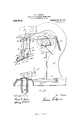
- FIG. 1 is a front elevation of the machine complete.
- Fig. 2 is a side elevation of the same except that one of the side plates is removed to show the interior parts more clearly, and the belt wheel is omitted.
- Fig. 3 is a vertical section showing more clearly the important working parts.
- Fig. 4 is a horizontal section taken on line H of Fig. 1.
- Fig. 5 is a plan View of the shoe holder or rest,
- Fig. 6 is a plan view of one of the metallic shank-pieces.
- A represents the base of itlhe machine, A the upright part and A the ead.
- B is the shoe rest which is mounted upon a supporting rod B said rod being attached to a foot lever by which the said shoe rest may be raised and lowered as desired.
- B is an adjustable gage connected to the shoe rest and assists in placing the boot or shoe in the exact place required during the working of the machine.
- the shank-piece which this machine is particularly designed to operate upon is shown in plan in Fig. 6; it is made of any suitable metal and is provided with barbs K K see Figs. 3 and 6.
- the position that the shank piece Kfoccupies on the machine, when ready to be applied to the sole, is shown in Fig. 2.
- the operating mechanism may be described as follows.
- the shank-piece holder L Figs. 2 and 3 is made with a holding start L, which engages with the opening at K formed in the shank-piece in punching up the barb K Fig. 6; the other end of the shank-piece is held by the spring pieces A A which clamp it by its edges and hold it frictionally only so that it may be readily removed after it is attached to the sole.
- the holder L is forked at one end so as to be guided by the fixed pin L Fig. 2.
- the lower edges of the side plates A A are shaped as shown in Fig. 2, so as to act in connection with the upper surface of the shoe holder B to cause the sole S to be forced temporarily to assume the contortions shown in Fig. 3 to allow the awls and the barbs to penetrate the said sole.
- a shank piece holding device comprising a shank piece holder having a start constructed to engage with one of the barb holes of the said piece, thereby holding the rear end of said shank piece, springs constructed to frictionally hold the front end of said shank piece; and means for operating said shank piece holder substantially as and for the purpose set forth.
- a shoe holding mechanism comprising a lower holder constructed to hold the shoe from the underside and having cross bosses which form a part of the surface of the holder upon which the outer side of the sole rests,
- a guard-gage attached to the said holder constructed to assist in placing the shoe in position; means for raising and lowering said holder; fixed side plates attached to the head part of the machine having their lower edges shaped to conform to the upper surface of the said holder whereby the upward movement of the shoe holder clamps the sole, to which the shank piece is to be attached, between the said holder and the lower edges of said side plates thereby molding the sole and forming ridges, awls for making holes in said ridges through which holes the barbs of the shank-pleces are forced as and for the purpose set forth.
Landscapes
- Footwear And Its Accessory, Manufacturing Method And Apparatuses (AREA)
Description
E. F. MOWER;
MACHINE FOR ATTAOHING SHANK PIECES.
APPLICATION FILED DBO. 10,1909.
Patented July '26, 1910.
3 BHEETB-SHIBET 1.
WITNEEEEZE THE NORRIS PETERS cm, WASHINGTON, c.
E. F. MOWER. MACHINE FOB-ATTAGHING SHANK PIECES.
APPLICATION FILED DEG. 10,1909.
Patented July 26, 1910.
3 SHEETS-SHEET 2.
'E. F. MOWER MACHINE FOR ATTAGHING SHANK PIECES.
APPLIOATIOH TILED DEG. 10,1909.
965,21 3. Patented July 26, 1910.
mums-sum a;
MATNEEEEWE kph-[3g THE NORRIS PETERS co. WASHINGTON, n. c.
TE STA EDWIN F. MOWER, 0F BOSTON, MASSACHUSETTS, ASSIGNOR T0 UNION SHANK COM- PANY, OF WHITMAN, MASSACHUSETTS, A CORPORATION OF MAINE.
MACHINE FOR ATTACHING SHANK-PIECES.
Specification of Letters Patent.
Application filed December 10, 1909. Serial No. 532,477.
To all whom it may concern:
Be it known that I, EDWIN F. MOWER, a citizen of the United States, resident of Boston, in the county of Suffolk and State of Massachusetts, have invented a new and useful Improvement in Machines for Attaching Shank-Pieces, of which the following, taken in connection with the accompanying drawings, is a specification.
My machine is especially adapted for attaching metallic shank-pieces to the soles of boots and shoes, and consists of peculiar mechanism which may be best understood by reference to the complete specification.
The object of the invention is to make a machine that will be rapid and reliable in its action.
This object I attain by the mechanism shown in the accompanying drawings, in which- Figure 1 is a front elevation of the machine complete. Fig. 2 is a side elevation of the same except that one of the side plates is removed to show the interior parts more clearly, and the belt wheel is omitted. Fig. 3 is a vertical section showing more clearly the important working parts. Fig. 4 is a horizontal section taken on line H of Fig. 1. Fig. 5 is a plan View of the shoe holder or rest, Fig. 6 is a plan view of one of the metallic shank-pieces.
In the drawings A represents the base of itlhe machine, A the upright part and A the ead.
B is the shoe rest which is mounted upon a supporting rod B said rod being attached to a foot lever by which the said shoe rest may be raised and lowered as desired.
B is an adjustable gage connected to the shoe rest and assists in placing the boot or shoe in the exact place required during the working of the machine.
The shank-piece which this machine is particularly designed to operate upon is shown in plan in Fig. 6; it is made of any suitable metal and is provided with barbs K K see Figs. 3 and 6. The position that the shank piece Kfoccupies on the machine, when ready to be applied to the sole, is shown in Fig. 2.
The operating mechanism may be described as follows. The shank-piece holder L Figs. 2 and 3 is made with a holding start L, which engages with the opening at K formed in the shank-piece in punching up the barb K Fig. 6; the other end of the shank-piece is held by the spring pieces A A which clamp it by its edges and hold it frictionally only so that it may be readily removed after it is attached to the sole. The holder L is forked at one end so as to be guided by the fixed pin L Fig. 2. The other end of the holder L is loosely held by the pin L in the slot at the lower end of the bent lever L which is pivoted to pivot L A cam L on the shaft I-I causes the lever L to operate in one direction and the spring L causes it to move in the other direction.
In order to make the barbs K K of the shank penetrate the sole more easily and certainly holes are made in the said sole; for this purpose I use the awls C and D. These awls are operated by the arms C and D which are linked together by the link E; the arm D is pivoted to the head. A by the screw pin D The arm 0 is rigidly attached to the rocker shaft C by a screw nut C The said rocker shaft has an arm 0* attached to it by a screw bolt C Fig. 1. The rocker arm 0 has a cam pin 0 constructed to engage with the cam groove C made in the face of the cam disk C For starting and stopping the machine a hand lever N is used; this lever works through the rod N and a clutch device N of any desired construction.
The lower edges of the side plates A A are shaped as shown in Fig. 2, so as to act in connection with the upper surface of the shoe holder B to cause the sole S to be forced temporarily to assume the contortions shown in Fig. 3 to allow the awls and the barbs to penetrate the said sole.
To operate this machine the user places a shank-piece K in position by hooking one end on to the holding start L and forcing the other end up between the springs A A now the shoe is placed on the holder B, then the holder is thrown up by a foot lever acting through the rod B this action brings the shoe up to the position shown in Fig. 3, the sole of the shoe being forced up hard against the under side of the shank inserting mechanism and parts of the sole are bent up by the bosses B B as shown; now the operator starts the machine and the awls O and D puncture the sole and are drawn back and out; then the shank-piece holder U, by the aid of the holding start L,
draws the shank back forcing the barbs K K into the sole; the next movement is to send the holder L back, which releases the shank-piece and the shoe holder B may be lowered and the shoe taken out with the shank-piece securely attached. And the machine is ready for another operation.
What I claim is- 1. In a shank-piece attaching machine, a shank piece holding device comprising a shank piece holder having a start constructed to engage with one of the barb holes of the said piece, thereby holding the rear end of said shank piece, springs constructed to frictionally hold the front end of said shank piece; and means for operating said shank piece holder substantially as and for the purpose set forth.
2. In a shank-piece attaching machine, a shoe holding mechanism comprising a lower holder constructed to hold the shoe from the underside and having cross bosses which form a part of the surface of the holder upon which the outer side of the sole rests,
a guard-gage attached to the said holder constructed to assist in placing the shoe in position; means for raising and lowering said holder; fixed side plates attached to the head part of the machine having their lower edges shaped to conform to the upper surface of the said holder whereby the upward movement of the shoe holder clamps the sole, to which the shank piece is to be attached, between the said holder and the lower edges of said side plates thereby molding the sole and forming ridges, awls for making holes in said ridges through which holes the barbs of the shank-pleces are forced as and for the purpose set forth.
In testimony whereof, I have signed my name to this specification in the presence of two subscribing witnesses, on this 29th day of November A. D. 1909.
EDWIN F. MOWER.
WVit-nesses:
FRANK G. PARKER, HARRY C. Loon.
Priority Applications (1)
| Application Number | Priority Date | Filing Date | Title |
|---|---|---|---|
| US53247709A US965213A (en) | 1909-12-10 | 1909-12-10 | Machine for attaching shank-pieces. |
Applications Claiming Priority (1)
| Application Number | Priority Date | Filing Date | Title |
|---|---|---|---|
| US53247709A US965213A (en) | 1909-12-10 | 1909-12-10 | Machine for attaching shank-pieces. |
Publications (1)
| Publication Number | Publication Date |
|---|---|
| US965213A true US965213A (en) | 1910-07-26 |
Family
ID=3033610
Family Applications (1)
| Application Number | Title | Priority Date | Filing Date |
|---|---|---|---|
| US53247709A Expired - Lifetime US965213A (en) | 1909-12-10 | 1909-12-10 | Machine for attaching shank-pieces. |
Country Status (1)
| Country | Link |
|---|---|
| US (1) | US965213A (en) |
-
1909
- 1909-12-10 US US53247709A patent/US965213A/en not_active Expired - Lifetime
Similar Documents
| Publication | Publication Date | Title |
|---|---|---|
| US2618400A (en) | Method of and machine for inserting blind fastenings | |
| US1018638A (en) | Shoe-support for pounding-up machines. | |
| US446885A (en) | Machine | |
| US582502A (en) | Graham | |
| US1502014A (en) | Heel-clamping machine | |
| US1852152A (en) | Work support | |
| US460526A (en) | edgerly | |
| US243555A (en) | Tire-upsetter | |
| US968755A (en) | Tack-pulling machine. | |
| US36607A (en) | Improved machine for attaching heels to boots and shoes, and polishing the same | |
| US1277764A (en) | Heel-breasting machine. | |
| US1018526A (en) | Pounding-up machine. | |
| US418341A (en) | Machine for attaching metal plates | |
| US324086A (en) | Signoes of one-thied to chaeles h | |
| US312748A (en) | Button-attaching machine | |
| US1101603A (en) | Sole-machine. | |
| US493196A (en) | Relasting-machine | |
| US444858A (en) | Sachusetts | |
| US1218649A (en) | Shoe-nailing machine. | |
| US163475A (en) | Improvement in jack-attachments for nailing-machines for boots and shoes | |
| USRE19297E (en) | Apparatus fok attaching heels to | |
| USRE8487E (en) | Improvement in lasting-machines | |
| US259687A (en) | Heel-nailing machine | |
| US1288521A (en) | Machine for operating upon heels. | |
| US3212693A (en) | Shoe machinery |