US9649934B2 - Driving safety controlling system and driving safety controlling method using same - Google Patents
Driving safety controlling system and driving safety controlling method using same Download PDFInfo
- Publication number
- US9649934B2 US9649934B2 US14/716,538 US201514716538A US9649934B2 US 9649934 B2 US9649934 B2 US 9649934B2 US 201514716538 A US201514716538 A US 201514716538A US 9649934 B2 US9649934 B2 US 9649934B2
- Authority
- US
- United States
- Prior art keywords
- sensing data
- driving safety
- unique identifier
- vehicle
- identifier
- Prior art date
- Legal status (The legal status is an assumption and is not a legal conclusion. Google has not performed a legal analysis and makes no representation as to the accuracy of the status listed.)
- Active
Links
Images


Classifications
-
- B—PERFORMING OPERATIONS; TRANSPORTING
- B60—VEHICLES IN GENERAL
- B60K—ARRANGEMENT OR MOUNTING OF PROPULSION UNITS OR OF TRANSMISSIONS IN VEHICLES; ARRANGEMENT OR MOUNTING OF PLURAL DIVERSE PRIME-MOVERS IN VEHICLES; AUXILIARY DRIVES FOR VEHICLES; INSTRUMENTATION OR DASHBOARDS FOR VEHICLES; ARRANGEMENTS IN CONNECTION WITH COOLING, AIR INTAKE, GAS EXHAUST OR FUEL SUPPLY OF PROPULSION UNITS IN VEHICLES
- B60K28/00—Safety devices for propulsion-unit control, specially adapted for, or arranged in, vehicles, e.g. preventing fuel supply or ignition in the event of potentially dangerous conditions
- B60K28/02—Safety devices for propulsion-unit control, specially adapted for, or arranged in, vehicles, e.g. preventing fuel supply or ignition in the event of potentially dangerous conditions responsive to conditions relating to the driver
- B60K28/06—Safety devices for propulsion-unit control, specially adapted for, or arranged in, vehicles, e.g. preventing fuel supply or ignition in the event of potentially dangerous conditions responsive to conditions relating to the driver responsive to incapacity of driver
-
- A—HUMAN NECESSITIES
- A61—MEDICAL OR VETERINARY SCIENCE; HYGIENE
- A61B—DIAGNOSIS; SURGERY; IDENTIFICATION
- A61B5/00—Measuring for diagnostic purposes; Identification of persons
- A61B5/16—Devices for psychotechnics; Testing reaction times ; Devices for evaluating the psychological state
- A61B5/18—Devices for psychotechnics; Testing reaction times ; Devices for evaluating the psychological state for vehicle drivers or machine operators
-
- B—PERFORMING OPERATIONS; TRANSPORTING
- B60—VEHICLES IN GENERAL
- B60R—VEHICLES, VEHICLE FITTINGS, OR VEHICLE PARTS, NOT OTHERWISE PROVIDED FOR
- B60R25/00—Fittings or systems for preventing or indicating unauthorised use or theft of vehicles
- B60R25/20—Means to switch the anti-theft system on or off
- B60R25/25—Means to switch the anti-theft system on or off using biometry
- B60R25/252—Fingerprint recognition
-
- B—PERFORMING OPERATIONS; TRANSPORTING
- B60—VEHICLES IN GENERAL
- B60W—CONJOINT CONTROL OF VEHICLE SUB-UNITS OF DIFFERENT TYPE OR DIFFERENT FUNCTION; CONTROL SYSTEMS SPECIALLY ADAPTED FOR HYBRID VEHICLES; ROAD VEHICLE DRIVE CONTROL SYSTEMS FOR PURPOSES NOT RELATED TO THE CONTROL OF A PARTICULAR SUB-UNIT
- B60W50/00—Details of control systems for road vehicle drive control not related to the control of a particular sub-unit, e.g. process diagnostic or vehicle driver interfaces
- B60W50/08—Interaction between the driver and the control system
- B60W50/12—Limiting control by the driver depending on vehicle state, e.g. interlocking means for the control input for preventing unsafe operation
-
- B—PERFORMING OPERATIONS; TRANSPORTING
- B60—VEHICLES IN GENERAL
- B60W—CONJOINT CONTROL OF VEHICLE SUB-UNITS OF DIFFERENT TYPE OR DIFFERENT FUNCTION; CONTROL SYSTEMS SPECIALLY ADAPTED FOR HYBRID VEHICLES; ROAD VEHICLE DRIVE CONTROL SYSTEMS FOR PURPOSES NOT RELATED TO THE CONTROL OF A PARTICULAR SUB-UNIT
- B60W50/00—Details of control systems for road vehicle drive control not related to the control of a particular sub-unit, e.g. process diagnostic or vehicle driver interfaces
- B60W50/08—Interaction between the driver and the control system
- B60W50/14—Means for informing the driver, warning the driver or prompting a driver intervention
-
- G07C9/00087—
-
- G07C9/00126—
-
- G07C9/00158—
-
- G—PHYSICS
- G07—CHECKING-DEVICES
- G07C—TIME OR ATTENDANCE REGISTERS; REGISTERING OR INDICATING THE WORKING OF MACHINES; GENERATING RANDOM NUMBERS; VOTING OR LOTTERY APPARATUS; ARRANGEMENTS, SYSTEMS OR APPARATUS FOR CHECKING NOT PROVIDED FOR ELSEWHERE
- G07C9/00—Individual registration on entry or exit
- G07C9/20—Individual registration on entry or exit involving the use of a pass
- G07C9/22—Individual registration on entry or exit involving the use of a pass in combination with an identity check of the pass holder
- G07C9/25—Individual registration on entry or exit involving the use of a pass in combination with an identity check of the pass holder using biometric data, e.g. fingerprints, iris scans or voice recognition
- G07C9/257—Individual registration on entry or exit involving the use of a pass in combination with an identity check of the pass holder using biometric data, e.g. fingerprints, iris scans or voice recognition electronically
-
- G—PHYSICS
- G07—CHECKING-DEVICES
- G07C—TIME OR ATTENDANCE REGISTERS; REGISTERING OR INDICATING THE WORKING OF MACHINES; GENERATING RANDOM NUMBERS; VOTING OR LOTTERY APPARATUS; ARRANGEMENTS, SYSTEMS OR APPARATUS FOR CHECKING NOT PROVIDED FOR ELSEWHERE
- G07C9/00—Individual registration on entry or exit
- G07C9/30—Individual registration on entry or exit not involving the use of a pass
- G07C9/32—Individual registration on entry or exit not involving the use of a pass in combination with an identity check
- G07C9/37—Individual registration on entry or exit not involving the use of a pass in combination with an identity check using biometric data, e.g. fingerprints, iris scans or voice recognition
-
- B—PERFORMING OPERATIONS; TRANSPORTING
- B60—VEHICLES IN GENERAL
- B60W—CONJOINT CONTROL OF VEHICLE SUB-UNITS OF DIFFERENT TYPE OR DIFFERENT FUNCTION; CONTROL SYSTEMS SPECIALLY ADAPTED FOR HYBRID VEHICLES; ROAD VEHICLE DRIVE CONTROL SYSTEMS FOR PURPOSES NOT RELATED TO THE CONTROL OF A PARTICULAR SUB-UNIT
- B60W40/00—Estimation or calculation of non-directly measurable driving parameters for road vehicle drive control systems not related to the control of a particular sub unit, e.g. by using mathematical models
- B60W40/08—Estimation or calculation of non-directly measurable driving parameters for road vehicle drive control systems not related to the control of a particular sub unit, e.g. by using mathematical models related to drivers or passengers
- B60W2040/0872—Driver physiology
-
- B—PERFORMING OPERATIONS; TRANSPORTING
- B60—VEHICLES IN GENERAL
- B60W—CONJOINT CONTROL OF VEHICLE SUB-UNITS OF DIFFERENT TYPE OR DIFFERENT FUNCTION; CONTROL SYSTEMS SPECIALLY ADAPTED FOR HYBRID VEHICLES; ROAD VEHICLE DRIVE CONTROL SYSTEMS FOR PURPOSES NOT RELATED TO THE CONTROL OF A PARTICULAR SUB-UNIT
- B60W50/00—Details of control systems for road vehicle drive control not related to the control of a particular sub-unit, e.g. process diagnostic or vehicle driver interfaces
- B60W50/08—Interaction between the driver and the control system
- B60W50/14—Means for informing the driver, warning the driver or prompting a driver intervention
- B60W2050/143—Alarm means
-
- B—PERFORMING OPERATIONS; TRANSPORTING
- B60—VEHICLES IN GENERAL
- B60W—CONJOINT CONTROL OF VEHICLE SUB-UNITS OF DIFFERENT TYPE OR DIFFERENT FUNCTION; CONTROL SYSTEMS SPECIALLY ADAPTED FOR HYBRID VEHICLES; ROAD VEHICLE DRIVE CONTROL SYSTEMS FOR PURPOSES NOT RELATED TO THE CONTROL OF A PARTICULAR SUB-UNIT
- B60W2540/00—Input parameters relating to occupants
- B60W2540/043—Identity of occupants
-
- B—PERFORMING OPERATIONS; TRANSPORTING
- B60—VEHICLES IN GENERAL
- B60W—CONJOINT CONTROL OF VEHICLE SUB-UNITS OF DIFFERENT TYPE OR DIFFERENT FUNCTION; CONTROL SYSTEMS SPECIALLY ADAPTED FOR HYBRID VEHICLES; ROAD VEHICLE DRIVE CONTROL SYSTEMS FOR PURPOSES NOT RELATED TO THE CONTROL OF A PARTICULAR SUB-UNIT
- B60W2540/00—Input parameters relating to occupants
- B60W2540/221—Physiology, e.g. weight, heartbeat, health or special needs
Definitions
- the subject matter herein generally relates to driving safety controlling systems and driving safety controlling methods using same.
- the wearable devices such as wearable glass, wearable watch, or the like, are welcome for more and more users.
- the wearable devices can be used to monitor the driving safety of the vehicle.
- the wearable devices cannot be matched with the vehicles accurately.
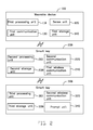
- FIG. 1 is a block diagram of an embodiment of a driving safety controlling system.
- FIG. 2 is a block diagram of an embodiment of an operating environment of the driving safety controlling system shown in FIG. 1 .
- FIG. 3 is a flowchart of an embodiment of a driving safety controlling method.
- FIG. 1 shows a driving safety controlling system 1 .
- the driving safety controlling system 1 can be run on but not limited to a wearable device 100 , a smart key 200 and a vehicle 300 which are shown on FIG. 2 .
- the wearable device 100 can be but not limited to a wearable glass, a wearable watch, a wearable cloth, or the like.
- the wearable device 100 can include a first processing unit 110 , a sense unit 120 , a first communication unit 130 and a first storage unit 140 .
- the sense unit 120 can be located on many locations of the wearable device 100 .
- the sense unit 120 can sense a user's physiological status, such as blood pressure, pulse rate, blink response, the number of eye-rolling or the like, and further generate a sensing data.
- the first storage unit 140 can be used to store the sensing data.
- the first communication unit 130 can be but not limited to Bluetooth, WiFi, RFID or other suitable communication device.
- the smart key 200 can include a second processing unit 210 , a second communication unit 220 , a second storage unit 230 and a first wireless communication unit 240 .
- the second communication unit 220 can be but not limited to Bluetooth, WiFi, RFID or other suitable communication device.
- the second communication unit 220 and the first communication unit 130 can cooperatively establish a communication between the wearable device 100 and the smart key 200 .
- the second storage unit 230 can be used to store a unique identifier.
- the first wireless communication unit 240 can be used to transmit a high-frequency signal containing the sensing data and the unique identifier.
- the vehicle 300 can include a third processing unit 310 , a second wireless communication unit 320 , a third storage unit 330 and a prompt unit 340 .
- the third storage unit 330 can store a range recording a user's physiological status and a predefined identifier.
- the second wireless communication unit 320 can be used to receive the high-frequency signal.
- the first storage unit 140 , the second storage unit 230 and the third storage unit 330 can be an internal storage controlling system, such as a flash memory, a random access memory (RAM) for temporary storage of information, and/or a read-memory (ROM) for permanent storage of information.
- an internal storage controlling system such as a flash memory, a random access memory (RAM) for temporary storage of information, and/or a read-memory (ROM) for permanent storage of information.
- the first storage unit 140 , the second storage unit 230 and the third storage unit 330 can also be a storage controlling system, such as a hard disk, a storage card, or a data storage medium.
- the first storage unit 140 , the second storage unit 230 and the third storage unit 330 can include volatile and/or non-volatile storage devices.
- the first storage unit 140 , the second storage unit 230 and the third storage unit 330 can include two or more storage devices such that one storage device is a memory and the other storage device is a hard drive. Additionally, the first storage unit 140 , the second storage unit 230 and the third storage unit 330 can be respectively located either entirely or partially external relative to the wearable device 100 , the smart key 200 or the vehicle 300 .
- the first processing unit 110 , the second processing unit 210 and the third processing unit 310 can be a central processing unit, a digital signal processor, or a single chip, for example.
- the driving safety controlling system 1 can include a number of modules, and the number of modules can include a matching module 11 , an obtaining module 12 , a submitting module 13 , a transmitting module 14 , a determining module 15 and a prompting module 16 .
- the number of modules can be stored in the first storage unit 140 , and/or second storage unit 230 , and/or the third storage unit 330 , and further applied on the first processing unit 110 , and/or the second processing unit 210 , and/or the third processing unit 310 .
- the allocation module 10 , the first transmit control module 12 , the calculating module 14 , the matching module 11 , the obtaining module 12 and the submitting module 13 can be stored in the first storage unit 140 , and applied on the first processing unit 110 .
- the transmitting module 14 can be stored in the second storage unit 230 , and applied on the second processing unit 210 .
- the determining module 15 and the prompting module 16 can be stored in the third storage unit 330 , and applied on the third processing unit 310 .
- the matching module 11 can be used to control the first communication unit 130 of the wearable device 100 to match with the second communication unit 220 of the smart key 200 , such that the wearable device 100 can communicate with the smart key 200 .
- the obtaining module 12 can be used to obtain the sensing data, and the sensing data can include but not limited to a user's blood pressure, pulse rate, blink response, the number of eye-rolling or the like.
- the submitting module 13 can be used to submit the sensing data to the smart key 200 .
- the second communication unit 220 of the smart key 200 can receive the sensing data.
- the transmitting module 14 can be used to obtain the unique identifier from the second storage unit 230 , and further control the first wireless communication unit 240 to transmit a high-frequency signal containing the unique identifier and the sensing data.
- the second wireless communication unit 320 of the vehicle 300 can receive the high-frequency signal.
- the determining module 15 can be used to obtain the unique identifier and the sensing data from the high-frequency signal, and obtain the predefined identifier and the range from the third storage unit 330 , and compare the unique identifier with the predefined identifier, and further compare the sensing data with the range, if the unique identifier is matched with the predefined identifier and the sensing data is within the range, it is indicated that the user is in a normal state, if the unique identifier is matched with the predefined identifier, but the sensing data is not within the range, it is indicated that the user is in an abnormal state.
- the determining module 15 can be used to obtain the unique identifier and the sensing data from the high-frequency signal, and further obtain the predefined identifier from the third storage unit 330 , and compare the unique identifier with the predefined identifier, and determine whether the unique identifier is matched with the predefined identifier, and do not process the sensing data when determined that the unique identifier is not matched with the predefined identifier, and obtain the range from the third storage unit 330 when determined that the unique identifier is matched with the predefined identifier, and further compare the sensing data with the range; and determine whether the sensing data is within the range, and if the sensing data is within the range, it is indicated that the user is in a normal state, and if the sensing data is not within the range, it is indicated that the user is in an abnormal state.
- the prompting module 16 can be used to control the prompt unit 340 to generate a prompting when determined that the unique identifier is matched with the predefined identifier and the sensing data is within the range.
- the prompting can be but not limited to alarm prompting, voice prompting, light prompting or the like.
- the vehicle 300 After the prompt unit 340 has prompted predefined time duration, if there is still no response, the vehicle 300 would be stopped, such that fatigue driving, drunk driving or the like can be avoided effectively.
- FIG. 3 illustrates a flowchart of a driving safety controlling method.
- the control controlling method is provided by way of example, as there are a variety of ways to carry out the controlling method.
- the control controlling method described below can be carried out using the configurations illustrated in FIG. 1 , for example, and various elements of these figures are referenced in explaining the example controlling method.
- Each block shown in FIG. 3 represents one or more processes, controlling methods, or subroutines carried out in the example controlling method.
- the illustrated order of blocks is by example only and the order of the blocks can be changed. Additional blocks may be added or fewer blocks may be utilized, without departing from this disclosure.
- the example controlling method can begin at block 31 .
- a wearable device matches with a smart key.
- a matching module controls a first communication unit of the wearable device to match with a second communication unit of the smart key.
- the wearable device senses a user's physiological status, and further generates a sensing data.
- a sense unit senses a user's physiological status such as blood pressure, pulse rate, blink response, the number of eye-rolling or the like, and further generate the sensing data.
- the wearable device obtains the sensing data.
- an obtaining module obtains the sensing data.
- the wearable device submits the sensing data to the smart key.
- a submitting module controls a first communication unit of the wearable device to submit the sensing data to the smart key.
- the smart key receives the sensing data, and further transmits a high-frequency signal containing a unique identifier and the sensing data.
- the second communication unit of the smart key receives the sensing data, and an transmitting module obtains the unique identifier from a second storage unit of the smart key, and further controls a first wireless communication unit to transmit a high-frequency signal containing the unique identifier and the sensing data.
- a second wireless communication unit of the vehicle receives the high-frequency signal.
- the vehicle obtains a predefined identifier, and compares the unique identifier with the predefined identifier, and determines whether the unique identifier is matched with the predefined identifier, if yes, the process goes to block 37 , otherwise, the process goes to end.
- a determining module obtains the unique identifier and the sensing data from the high-frequency signal, and obtains the predefined identifier from a third storage unit, and compares the unique identifier with the predefined identifier, and determines whether the unique identifier is matched with the predefined identifier, if yes, the process goes to block 37 , otherwise, the process goes to end.
- the vehicle obtains a range from the third storage unit, and further compares the sensing data with the range; and determines whether the sensing data is within the range, if yes, the process goes to block 38 , otherwise, the process goes to end.
- the determining module obtains the range from the third storage unit, and further compares the sensing data with the range; and determines whether the sensing data is within the range, if yes, the process goes to block 38 , otherwise, the process goes to end.
- a prompting module controls a prompt unit to generate a prompting.
- the first wireless communication unit 240 and the second communication unit 320 can communicate with each other by transmitting a low-frequency signal and receiving a low-frequency signal.
- the first wireless communication unit 240 and the second wireless communication unit 320 can communicate with each other by transmitting a low-frequency signal or a high-frequency signal, and receiving a low-frequency signal or a high-frequency signal.
- the low-frequency signal and the high-frequency signal can be both called communication signal.
- the “match” can be that the predefined identifier is same with the unique identifier, or the predefined identifier is only corresponded to the unique identifier.
Landscapes
- Engineering & Computer Science (AREA)
- Health & Medical Sciences (AREA)
- Automation & Control Theory (AREA)
- Human Computer Interaction (AREA)
- Life Sciences & Earth Sciences (AREA)
- Mechanical Engineering (AREA)
- Physics & Mathematics (AREA)
- Transportation (AREA)
- General Physics & Mathematics (AREA)
- Social Psychology (AREA)
- Biomedical Technology (AREA)
- Developmental Disabilities (AREA)
- Educational Technology (AREA)
- Hospice & Palliative Care (AREA)
- Psychiatry (AREA)
- Psychology (AREA)
- Veterinary Medicine (AREA)
- Public Health (AREA)
- Biophysics (AREA)
- Pathology (AREA)
- Child & Adolescent Psychology (AREA)
- Heart & Thoracic Surgery (AREA)
- Medical Informatics (AREA)
- Molecular Biology (AREA)
- Surgery (AREA)
- Animal Behavior & Ethology (AREA)
- General Health & Medical Sciences (AREA)
- Combustion & Propulsion (AREA)
- Chemical & Material Sciences (AREA)
- Lock And Its Accessories (AREA)
- Computer Networks & Wireless Communication (AREA)
- Traffic Control Systems (AREA)
Abstract
Description
Claims (10)
Applications Claiming Priority (3)
| Application Number | Priority Date | Filing Date | Title |
|---|---|---|---|
| TW103146681 | 2014-12-31 | ||
| TW103146681A | 2014-12-31 | ||
| TW103146681A TWI639523B (en) | 2014-12-31 | 2014-12-31 | Driving safety system and driving safety method |
Publications (2)
| Publication Number | Publication Date |
|---|---|
| US20160189449A1 US20160189449A1 (en) | 2016-06-30 |
| US9649934B2 true US9649934B2 (en) | 2017-05-16 |
Family
ID=56164859
Family Applications (1)
| Application Number | Title | Priority Date | Filing Date |
|---|---|---|---|
| US14/716,538 Active US9649934B2 (en) | 2014-12-31 | 2015-05-19 | Driving safety controlling system and driving safety controlling method using same |
Country Status (2)
| Country | Link |
|---|---|
| US (1) | US9649934B2 (en) |
| TW (1) | TWI639523B (en) |
Families Citing this family (1)
| Publication number | Priority date | Publication date | Assignee | Title |
|---|---|---|---|---|
| CN112498290B (en) * | 2020-11-09 | 2022-04-15 | 李涛 | Intelligent traffic safety auditing system and device |
Citations (8)
| Publication number | Priority date | Publication date | Assignee | Title |
|---|---|---|---|---|
| US20040236701A1 (en) * | 2001-07-10 | 2004-11-25 | American Express Travel Related Services Company, Inc. | Method and system for proffering multiple biometrics for use with a fob |
| US20060219776A1 (en) * | 2003-11-17 | 2006-10-05 | Dpd Patent Trust | Rfid reader with multiple interfaces |
| US20090121833A1 (en) * | 2004-11-16 | 2009-05-14 | Koninklijke Philips Electronics N.V. | Identification system and method of operating same |
| US20140282931A1 (en) * | 2013-03-18 | 2014-09-18 | Ford Global Technologies, Llc | System for vehicular biometric access and personalization |
| US20140266597A1 (en) * | 2013-03-15 | 2014-09-18 | Tyfone, Inc. | Personal digital identity device with motion sensor responsive to user interaction |
| US20140309870A1 (en) * | 2012-03-14 | 2014-10-16 | Flextronics Ap, Llc | Vehicle-based multimode discovery |
| US20150220109A1 (en) * | 2013-11-29 | 2015-08-06 | Mechio Inc. | Wearable computing device |
| US20160001781A1 (en) * | 2013-03-15 | 2016-01-07 | Honda Motor Co., Ltd. | System and method for responding to driver state |
Family Cites Families (6)
| Publication number | Priority date | Publication date | Assignee | Title |
|---|---|---|---|---|
| CN100483443C (en) * | 2004-07-23 | 2009-04-29 | 浙江华立通信集团有限公司 | Biological key and biological lock |
| CN101359407A (en) * | 2007-08-03 | 2009-02-04 | 财团法人车辆研究测试中心 | Vehicle biological feature identification use authority management system and method thereof |
| CN201076451Y (en) * | 2007-10-26 | 2008-06-25 | 沈渊瑶 | Action carrier with physiological signal processing and monitoring system |
| CN202417030U (en) * | 2011-12-27 | 2012-09-05 | 济南吉利汽车有限公司 | Watch type automobile key |
| TWM444954U (en) * | 2012-03-28 | 2013-01-11 | Chin-Feng Liu | Mobile vehicle control module with physiological monitoring function |
| CN104133366A (en) * | 2014-08-25 | 2014-11-05 | 宁波贝思转化医学研究中心有限公司 | Wrist watch device with intelligent health monitoring and alarming system and method thereof |
-
2014
- 2014-12-31 TW TW103146681A patent/TWI639523B/en active
-
2015
- 2015-05-19 US US14/716,538 patent/US9649934B2/en active Active
Patent Citations (8)
| Publication number | Priority date | Publication date | Assignee | Title |
|---|---|---|---|---|
| US20040236701A1 (en) * | 2001-07-10 | 2004-11-25 | American Express Travel Related Services Company, Inc. | Method and system for proffering multiple biometrics for use with a fob |
| US20060219776A1 (en) * | 2003-11-17 | 2006-10-05 | Dpd Patent Trust | Rfid reader with multiple interfaces |
| US20090121833A1 (en) * | 2004-11-16 | 2009-05-14 | Koninklijke Philips Electronics N.V. | Identification system and method of operating same |
| US20140309870A1 (en) * | 2012-03-14 | 2014-10-16 | Flextronics Ap, Llc | Vehicle-based multimode discovery |
| US20140266597A1 (en) * | 2013-03-15 | 2014-09-18 | Tyfone, Inc. | Personal digital identity device with motion sensor responsive to user interaction |
| US20160001781A1 (en) * | 2013-03-15 | 2016-01-07 | Honda Motor Co., Ltd. | System and method for responding to driver state |
| US20140282931A1 (en) * | 2013-03-18 | 2014-09-18 | Ford Global Technologies, Llc | System for vehicular biometric access and personalization |
| US20150220109A1 (en) * | 2013-11-29 | 2015-08-06 | Mechio Inc. | Wearable computing device |
Also Published As
| Publication number | Publication date |
|---|---|
| TW201625026A (en) | 2016-07-01 |
| US20160189449A1 (en) | 2016-06-30 |
| TWI639523B (en) | 2018-11-01 |
Similar Documents
| Publication | Publication Date | Title |
|---|---|---|
| EP3746879B1 (en) | Secure blockchain integrated circuit | |
| US20160101749A1 (en) | Method and system of auto-adjusting vehicle settings | |
| KR102303909B1 (en) | Mobile terminal and method for controlling application for vehicle | |
| US9663112B2 (en) | Adaptive driver identification fusion | |
| EP4171974B1 (en) | Securely pairing a vehicle-mounted wireless sensor with a central device | |
| CN105100192B (en) | Method and system for starting application | |
| EP4116110B1 (en) | Real-time tire monitoring system | |
| US9613515B2 (en) | Method and apparatus for occupant customized wellness monitoring | |
| US9746833B2 (en) | Electronic device and smart method for controlling alarm | |
| US20180246508A1 (en) | Electronic device for controlling vehicle, and operating method thereof | |
| US11627612B2 (en) | Method and apparatus for efficient vehicle data reporting | |
| KR20170002969A (en) | Electronic apparatus and methof for performing authentication | |
| RU2012138384A (en) | VEHICLE INDIVIDUAL FOR DRIVER CONFIGURATION | |
| CN105138529A (en) | Connected vehicle predictive quality | |
| US10547730B2 (en) | Method and apparatus for vehicular emergency call | |
| CN105501227A (en) | Road emergency activation | |
| US9656630B2 (en) | Control system and control method for vehicle anti-theft | |
| US9478073B2 (en) | Friendly maintenance and recall notifications | |
| US20160337357A1 (en) | Electronic device and method for monitoring the taking of photos | |
| KR20170101683A (en) | Electronic Device for Using Traffic Information and Method Thereof | |
| US20160189457A1 (en) | Control system and control method for vehicle anti-theft | |
| US9649934B2 (en) | Driving safety controlling system and driving safety controlling method using same | |
| EP4109816B1 (en) | Context-based response to attacks against autonomous systems | |
| US10952055B2 (en) | Wireless communication system, vehicle, smart apparatus, and controlling method thereof | |
| KR102277519B1 (en) | Vehicle infotainment system and method for providing driver customized service |
Legal Events
| Date | Code | Title | Description |
|---|---|---|---|
| AS | Assignment |
Owner name: HON HAI PRECISION INDUSTRY CO., LTD., TAIWAN Free format text: ASSIGNMENT OF ASSIGNORS INTEREST;ASSIGNOR:CHEN, WEI-AN;REEL/FRAME:035673/0461 Effective date: 20150326 |
|
| STCF | Information on status: patent grant |
Free format text: PATENTED CASE |
|
| AS | Assignment |
Owner name: FOXCONN INTERCONNECT TECHNOLOGY LIMITED, CAYMAN IS Free format text: ASSIGNMENT OF ASSIGNORS INTEREST;ASSIGNOR:HON HAI PRECISION INDUSTRY CO., LTD.;REEL/FRAME:050898/0896 Effective date: 20180921 |
|
| MAFP | Maintenance fee payment |
Free format text: PAYMENT OF MAINTENANCE FEE, 4TH YEAR, LARGE ENTITY (ORIGINAL EVENT CODE: M1551); ENTITY STATUS OF PATENT OWNER: LARGE ENTITY Year of fee payment: 4 |
|
| MAFP | Maintenance fee payment |
Free format text: PAYMENT OF MAINTENANCE FEE, 8TH YEAR, LARGE ENTITY (ORIGINAL EVENT CODE: M1552); ENTITY STATUS OF PATENT OWNER: LARGE ENTITY Year of fee payment: 8 |