US9643522B2 - Orthopedic cushion for a seat - Google Patents
Orthopedic cushion for a seat Download PDFInfo
- Publication number
- US9643522B2 US9643522B2 US14/520,787 US201414520787A US9643522B2 US 9643522 B2 US9643522 B2 US 9643522B2 US 201414520787 A US201414520787 A US 201414520787A US 9643522 B2 US9643522 B2 US 9643522B2
- Authority
- US
- United States
- Prior art keywords
- seat cushion
- seat
- envelope
- occupant
- cells
- Prior art date
- Legal status (The legal status is an assumption and is not a legal conclusion. Google has not performed a legal analysis and makes no representation as to the accuracy of the status listed.)
- Active, expires
Links
- 230000000399 orthopedic effect Effects 0.000 title claims abstract description 10
- 239000012530 fluid Substances 0.000 claims abstract description 27
- 238000004891 communication Methods 0.000 claims abstract description 10
- 230000000994 depressogenic effect Effects 0.000 claims abstract description 7
- 239000000463 material Substances 0.000 claims description 5
- 230000008878 coupling Effects 0.000 claims description 4
- 238000010168 coupling process Methods 0.000 claims description 4
- 238000005859 coupling reaction Methods 0.000 claims description 4
- 239000000203 mixture Substances 0.000 claims description 4
- 229920002635 polyurethane Polymers 0.000 claims description 4
- 239000004814 polyurethane Substances 0.000 claims description 4
- 238000003466 welding Methods 0.000 claims description 4
- 238000004519 manufacturing process Methods 0.000 description 14
- 230000037396 body weight Effects 0.000 description 6
- 238000009423 ventilation Methods 0.000 description 6
- 238000000034 method Methods 0.000 description 5
- 208000014617 hemorrhoid Diseases 0.000 description 4
- 206010013082 Discomfort Diseases 0.000 description 3
- 208000002193 Pain Diseases 0.000 description 3
- 230000036407 pain Effects 0.000 description 3
- PEDCQBHIVMGVHV-UHFFFAOYSA-N Glycerine Chemical compound OCC(O)CO PEDCQBHIVMGVHV-UHFFFAOYSA-N 0.000 description 2
- XUIMIQQOPSSXEZ-UHFFFAOYSA-N Silicon Chemical compound [Si] XUIMIQQOPSSXEZ-UHFFFAOYSA-N 0.000 description 2
- 210000000436 anus Anatomy 0.000 description 2
- 239000006260 foam Substances 0.000 description 2
- 210000004392 genitalia Anatomy 0.000 description 2
- 238000012986 modification Methods 0.000 description 2
- 230000004048 modification Effects 0.000 description 2
- 229910052710 silicon Inorganic materials 0.000 description 2
- 239000010703 silicon Substances 0.000 description 2
- 239000000853 adhesive Substances 0.000 description 1
- 230000000712 assembly Effects 0.000 description 1
- 238000000429 assembly Methods 0.000 description 1
- 210000001217 buttock Anatomy 0.000 description 1
- 230000001413 cellular effect Effects 0.000 description 1
- 238000010276 construction Methods 0.000 description 1
- 238000011161 development Methods 0.000 description 1
- 238000006073 displacement reaction Methods 0.000 description 1
- 229920001971 elastomer Polymers 0.000 description 1
- 229920001821 foam rubber Polymers 0.000 description 1
- 235000011187 glycerol Nutrition 0.000 description 1
- 230000002401 inhibitory effect Effects 0.000 description 1
- 210000004197 pelvis Anatomy 0.000 description 1
- 210000002640 perineum Anatomy 0.000 description 1
- 239000004033 plastic Substances 0.000 description 1
- 229920003023 plastic Polymers 0.000 description 1
- 230000002035 prolonged effect Effects 0.000 description 1
- 238000011160 research Methods 0.000 description 1
- 239000012858 resilient material Substances 0.000 description 1
- 239000007787 solid Substances 0.000 description 1
- 230000035900 sweating Effects 0.000 description 1
- 210000003905 vulva Anatomy 0.000 description 1
Images


Classifications
-
- B—PERFORMING OPERATIONS; TRANSPORTING
- B60—VEHICLES IN GENERAL
- B60N—SEATS SPECIALLY ADAPTED FOR VEHICLES; VEHICLE PASSENGER ACCOMMODATION NOT OTHERWISE PROVIDED FOR
- B60N2/00—Seats specially adapted for vehicles; Arrangement or mounting of seats in vehicles
- B60N2/58—Seat coverings
- B60N2/5816—Seat coverings attachments thereof
- B60N2/5825—Seat coverings attachments thereof by hooks, staples, clips, snap fasteners or the like
-
- B—PERFORMING OPERATIONS; TRANSPORTING
- B60—VEHICLES IN GENERAL
- B60N—SEATS SPECIALLY ADAPTED FOR VEHICLES; VEHICLE PASSENGER ACCOMMODATION NOT OTHERWISE PROVIDED FOR
- B60N2/00—Seats specially adapted for vehicles; Arrangement or mounting of seats in vehicles
- B60N2/58—Seat coverings
- B60N2/60—Removable protective coverings
- B60N2/6018—Removable protective coverings attachments thereof
- B60N2/6027—Removable protective coverings attachments thereof by hooks, staples, clips, snap fasteners or the like
-
- B—PERFORMING OPERATIONS; TRANSPORTING
- B60—VEHICLES IN GENERAL
- B60N—SEATS SPECIALLY ADAPTED FOR VEHICLES; VEHICLE PASSENGER ACCOMMODATION NOT OTHERWISE PROVIDED FOR
- B60N2/00—Seats specially adapted for vehicles; Arrangement or mounting of seats in vehicles
- B60N2/70—Upholstery springs ; Upholstery
- B60N2/7005—Upholstery springs ; Upholstery detachable
Definitions
- the present application relates to a seat cushion, and in particular, to an orthopedic seat cushion for a chair that inhibits pressure from being exerted on portions of an occupant's posterior.
- the transportation industry has been concerned with discomforts experienced by occupants sitting in automotive vehicle seats for extended periods of time. Some of these discomforts include excessive sweating due to lack of ventilation or pains from local pressure on the occupant's posterior created by prolonged sitting.
- the medical industry has been concerned with discomforts experienced by patients sitting and/or laying in various types of medical furniture, such as for example chairs, beds, wheelchairs, and the like, for extended periods of time.
- the present general inventive concept in various example embodiments, includes an orthopedic seat cushion for a seat or chair.
- Example embodiments of the present general inventive concept can be achieved by providing a seat cushion with an envelope comprising an upper and lower sheet sealed together to define an interior volume.
- the interior volume can be subdivided into a plurality of cells in fluid communication with each other to allow passage of air or other suitable fluid between contiguous cells.
- the seat cushion can define an opening penetrated through the sealed upper and lower sheet, oriented near the center of the envelope.
- the opening of the envelope can be shaped to allow clearance for a portion of an occupant's posterior.
- the opening of the envelope can further provide ventilation to the occupant, as well.
- the cells of the envelope can have a height dimension selected to inhibit portions of the occupant's posterior from contacting the seat.
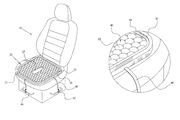
- FIGS. 1A-B illustrate an example seat cushion
- FIGS. 2A-B illustrate a top view and a cross-sectional view, taken at cut-line 2 B in FIG. 2A , of the example embodiment shown in FIG. 1 ;
- FIG. 3 illustrates a top view of an example die which may be used in the fabrication of the example embodiment sown in FIG. 1 ;
- FIGS. 4A-B illustrate partial top views of an example fabrication die and resulting cell structure of the cushion
- FIGS. 5A-B illustrate partial top views of an example fabrication die and resulting cell structure of the cushion
- FIGS. 6A-B illustrate partial top views of an example fabrication die and resulting cell structure of the cushion
- FIGS. 7A-B illustrate partial top views of an example fabrication die and resulting cell structure of the cushion.
- the cushion is generally defined by an envelope comprising an upper sheet and a lower sheet, sealed together at the perimeter of each sheet, forming an interior volume.
- the interior volume can be further subdivided into a plurality of cells, with adjacent cells being in fluid communication with one another.
- the subdivision of the interior volume into cells may be achieved by coupling the two sheets together at predetermined points through a number of different techniques, such as spot welding, applying adhesive agent, or the like.
- the cells of the envelope may be filled with air, gel, fluid, or any combination thereof.
- the cells of the envelope may be filled with a silicon and/or glycerin solution. However, other fluid may fill the cells of the envelope.
- the envelope defines an opening penetrated through the sealed upper and lower sheet, oriented near the center of envelope.
- the opening is shaped to allow clearance for a sensitive area of the occupant's posterior.
- the sensitive area may include, but is not limited to the occupant's' external genitalia, perineum, pubic area, vulva, anus, internal genitalia, pelvis, coccyx, etc. (hereinafter “sensitive area”).
- sensitive area the dimension of the opening is constrained to avoid the occupant from lapsing into the entrance of the opening.
- the dimension and shape of the opening is configured so that the cushion still provides sufficient support to occupant's buttocks while avoiding contact with occupant's sensitive area.
- the shape of the opening allows the cushion to avoid contact with the anus of an occupant suffering from hemorrhoids.
- the present general inventive concept is not limited to any particular shape for the opening of the envelope.
- the opening of the envelope provides ventilation to the occupant.
- a cell height dimension is selected which gives the cushion a thickness that inhibits the occupant's sensitive area from contacting the seat.
- the cells of the envelope compress, reducing the thickness of the cushion. If the thickness of the cushion reduces too much, the occupant's sensitive area may contact the seat area, adding discomfort to the occupant. Therefore, the cell dimension is selected so that when the occupant's bodyweight depresses the height of the cells, the cushion still maintains a thickness that inhibits the occupant's sensitive area from contacting seat.
- the height of each cell is 0.75 inches, providing the cushion a thickness so that the occupant's sensitive area avoids contact with the seat.
- the present general inventive concept is not limited to any particular cell dimension.
- the combination of the envelope's opening and fluid-filled cells enables the cushion to provide adequate support to the occupant's posterior while inhibiting stress applied to the occupant's sensitive area.
- an occupant suffering from hemorrhoids or any other similar pain may sit for an extended period of time with minimal discomfort.
- FIGS. 1A-B illustrates a seat 10 incorporating an example embodiment of a seat cushion 20 according to the present general inventive concept.
- the seat cushion 20 includes an envelope 21 comprising a sealed upper sheet 22 and lower sheet 24 .
- the envelope 21 also defines an opening 25 penetrated through the sealed upper sheet 22 and lower sheet 24 , oriented near the center of the envelope 21 .
- the envelope 21 is sealed along the perimeter of each sheet and along the periphery of the opening 25 .
- the upper sheet 22 and lower sheet 24 are perimetrically sealed directly to each other.
- An example seat cushion may include at least one strap 40 for securing the cushion to the seat and preventing movement thereof relative to the seat.
- the straps may have a hook 42 or clamp for attaching to the strap to a bracket or attachment device on the seat to assist in securing the cushion to the seat.
- An example seat cushion 20 may have pad portion 46 comprised of a plurality of cells 28 .
- the cushion may have a seal 48 or be sealed along the pad portion edges.
- the pad portion 46 may be confined within a tray 50 .
- the tray 50 may be configured to confine the pad and contain fluid and solids, such as food and/or drinks.
- the cushion and tray may be constructed of resilient material, such as plastic, rubber, etc. to facilitate conformity with the seat and the posterior of the operator.
- FIG. 2A illustrates a top view of an example embodiment of a seat cushion 20 .
- FIG. 2B illustrates a portion cross-sectional view, taken along line 2 B of FIG. 2A of an example embodiment seat cushion.
- the upper sheet 22 and lower sheet 24 are sealed together defining an interior volume.
- the upper sheet 22 and lower sheet 24 are connected by a number of spot welds 26 .
- Cells 28 are defined by the regions between the spot welds 26 , so that the shape of each cell 28 is determined by the positioning of the spot welds 26 .
- FIG. 2A illustrates a top view of an example embodiment of a seat cushion 20 .
- FIG. 2B illustrates a portion cross-sectional view, taken along line 2 B of FIG. 2A of an example embodiment seat cushion.
- the upper sheet 22 and lower sheet 24 are sealed together defining an interior volume.
- the upper sheet 22 and lower sheet 24 are connected by a number of spot welds 26 .
- Cells 28 are defined by the
- the spot welds 26 are arranged to form hexagonal cells 28 which are in fluid communication with each other, such that the hexagonal cells 28 comprise a hexagonal tessellation.
- the spot welds 26 may be arranged so that they form other cell shapes, such as substantially triangular or parallelogrammatic cells that are in fluid communication with each other.
- the envelope 21 defines an opening 25 penetrated through the sealed upper sheet 22 and lower sheet 24 , oriented near the center of the envelope 21 .
- the opening 25 of the envelope 21 defines a substantially oval shape, in which the width of opening 25 narrows slightly from the back end of the opening to the front end of the opening.
- the opening 25 is shaped to allow clearance for the occupant's hemorrhoids, which in one application may be the sensitive area of the occupant, but the dimension of the opening 25 is constrained so that the occupant does not lapse into the entrance of the opening 25 .
- those skilled in the art will recognize other shapes and dimensions for the opening of the envelope suitable for clearance of the occupant's sensitive area are contemplated.
- FIG. 3 illustrates a top view of an example mold 30 which may be used in the production of the example embodiment illustrated in FIG. 1 .
- the mold includes a plurality of pegs 32 .
- the pegs 32 provide the focal point where spot welds 26 are formed to couple the upper sheet 22 and lower sheet 24 .
- the pegs 32 are positioned and configured to form hexagonal cells 28 that are in fluid communication with each other, such that the hexagonal cells 28 comprise a hexagonal tessellation.
- the pegs may be arranged to form other cellular patterns, such as substantially triangular cells, substantially square cells, or etc. that are in fluid communication with each other.
- the cells 28 of the envelope 21 When fully assembled, the cells 28 of the envelope 21 may be filled with air, gel, fluid, or any combination thereof.
- the cells 28 of the envelope 21 are filled with a silicon solution, which will not freeze in most cold weather conditions.
- suitable fluids to fill the cells 28 of the envelope 21 without departing from the spirit and scope of the present general inventive concept.
- the upper sheet 22 and lower sheet 24 may be fabricated from a polymeric mixture.
- the upper sheet 22 and lower sheet 24 are fabricated from a polyurethane-based material.
- those skilled in the art will recognize other materials suitable to fabricate the upper sheet 22 and lower sheet 24 without departing from the spirit and scope of the present general inventive concept.
- the seat cushion is comprised of a pressure-reduction foam made from foam rubber or a gel-infused, heat wicking foam.
- the cells 28 have a height dimension that inhibits the occupant's sensitive area from contacting the seat 10 .
- the height of each cell 28 is defined substantially by the volume of fluid dispensed into the cells 28 along with the orientation of the spot welds 26 . Enlarging the diameter of each cell 28 by spacing the spot wells 26 further apart increases the cell height. Furthermore, filling the envelope 21 with more volume of fluid increases the cell height, as well. Thereby, a cell height that inhibits the occupant's sensitive area from contacting the seat 10 may be achieved by spacing the spot welds 26 further apart, dispensing more volume of fluid into the envelope 21 , or any combination thereof.
- the spot welds 26 are configured to form hexagon cells 28 with 2 inch diameters, and the envelope 21 is filled with enough fluid to produce cell heights that are proximately 0.75 inches, which allows the occupant's sensitive area to avoid contact with the seat 10 .
- the present general inventive concept encompasses numerous other potential sizes and dimensions that inhibit the occupant's sensitive area from contacting the seat.
- FIGS. 4A-B illustrate partial top views of an example fabrication die and resulting cell structure of a seat cushion. As illustrated in FIG. 4A , the pegs 32 are arranged so that the upper and lower sheets are coupled at points that form substantially triangular cell patterns as illustrated in FIG. 4B .
- FIGS. 5A-B illustrate partial top views of an example fabrication die and resulting cell structure of a seat cushion. As illustrated in FIG. 5A , the pegs 32 are arranged so that the upper and lower sheets are coupled at points that form substantially square cell patterns as illustrated in FIG. 5B .
- FIGS. 6A-B illustrate partial top views of an example fabrication die and resulting cell structure of a seat cushion. As illustrated in FIG. 6A , the pegs 32 are arranged so that the upper and lower sheets are coupled at points that form substantially rectangular cell patterns as illustrated in FIG. 6B .
- FIGS. 7A-B illustrate partial top views of an example fabrication die and resulting cell structure of a seat cushion. As illustrated in FIG. 7A , the pegs 32 are arranged so that the upper and lower sheets are coupled at points that form substantially parallelograms cell patterns as illustrated in FIG. 7B .
- example embodiments of applications for the seat cushion described herein may be (but not limited to) vehicle seats, wheelchairs, office chairs, stadium chairs or bleachers and chairs or seats in general in which extended sitting is required.
- An example orthopedic seat cushion for placement on a seat for supporting the weight of an occupant includes an envelope comprising an upper sheet and a lower sheet sealed together to define an interior volume, the envelope having a center.
- the interior volume is subdivided into a plurality of depressible cells wherein adjacent cells are in fluid communication with one another.
- the envelope has an opening through the upper sheet and lower sheet, wherein the opening is configured to allow clearance for a sensitive area of the occupant.
- the cells have a height that inhibits the sensitive area from contacting the seat when the cells are depressed by the weight of the occupant.
- the opening of the envelope has a substantially oval shape and the width of the opening narrows from the back end of the opening to the front end of the opening.
- the cells have one of the following shapes: hexagons; triangles and parallelograms.
- the height of at least one cell is greater than 0.5 inch.
- the seat cushion is configured such that not one of the cells is completely depressed by the weight of occupant.
- the opening is located about the center of the envelope.
- the cells are filled with at least one of the following: air; gel; polymeric material and fluid.
- the upper sheet and/or the lower sheet are comprised of at least one of the following: polyurethane and a polymeric mixture.
- the cells are formed by coupling the upper and lower sheet at predetermined points. In an example, the cells are formed by spot welding the upper and lower sheet at predetermined points.
- the upper and lower sheets do not contact.
- the seat cushion includes at least one strap configured to prevent movement of the seat cushion relative to the seat.
Abstract
An orthopedic seat cushion for placement on a seat for supporting the weight of an occupant includes an envelope comprising an upper sheet and a lower sheet sealed together to define an interior volume. The interior volume is subdivided into a plurality of depressible cells wherein adjacent cells are in fluid communication with one another. The envelope has an opening penetrated through the upper sheet and lower sheet, wherein the opening has a front end and a back end and is configured to allow clearance for a sensitive area of the occupant. At least one cell has a height dimension that inhibits the sensitive area from contacting the seat when the at least one cell is depressed by the weight of the occupant.
Description
The present application claims priority to Provisional Patent Application No. 61/894,686 filed on Oct. 23, 2013.
Not Applicable
1. Field of Invention
The present application relates to a seat cushion, and in particular, to an orthopedic seat cushion for a chair that inhibits pressure from being exerted on portions of an occupant's posterior.
2. Background
For many years the transportation industry has been concerned with discomforts experienced by occupants sitting in automotive vehicle seats for extended periods of time. Some of these discomforts include excessive sweating due to lack of ventilation or pains from local pressure on the occupant's posterior created by prolonged sitting. Likewise, the medical industry has been concerned with discomforts experienced by patients sitting and/or laying in various types of medical furniture, such as for example chairs, beds, wheelchairs, and the like, for extended periods of time.
These industries have each responded with a number of innovations, such as portable seat assemblies, seat inserts, and seat cushions, which provide cushioning, lumbar support, ventilation or combination thereof. However, occupants who suffer from pain in a particular, sensitive area, such as hemorrhoids, have had difficulty finding a seat cushion that inhibits pressure on the sensitive area and still provides orthopedic relief to the rest of the occupant's posterior. Furthermore, seat cushions designed to provide orthopedic relief to occupants tend to lack ventilation. Thus, a seat cushion that provides orthopedic relief but inhibits bodyweight pressure from being exerted on certain sensitive areas of the occupant, while still providing ventilation is desired.
The present general inventive concept, in various example embodiments, includes an orthopedic seat cushion for a seat or chair. Example embodiments of the present general inventive concept can be achieved by providing a seat cushion with an envelope comprising an upper and lower sheet sealed together to define an interior volume. The interior volume can be subdivided into a plurality of cells in fluid communication with each other to allow passage of air or other suitable fluid between contiguous cells. The seat cushion can define an opening penetrated through the sealed upper and lower sheet, oriented near the center of the envelope. The opening of the envelope can be shaped to allow clearance for a portion of an occupant's posterior. The opening of the envelope can further provide ventilation to the occupant, as well. The cells of the envelope can have a height dimension selected to inhibit portions of the occupant's posterior from contacting the seat.
Additional features and embodiments will be set forth in part in the description which follows, and, in part, will be obvious from the description, or may be learned by practice.
The following example embodiments are representative of example techniques and structures and not limited to these example embodiments. The above-mentioned features will become more clearly understood from the following detailed description read together with the drawings in which:
Reference will now be made to various example embodiments which are illustrated in the accompanying drawings and illustrations.
The following detailed description is provided to assist the reader in gaining a comprehensive understanding of the example structures and fabrication techniques described herein. Accordingly, various changes, modifications, and equivalents of the structures and fabrication techniques described herein will be suggested to those of ordinary skill in the art. The progression of fabrication operations described are merely examples, however, and the sequence of operations is not limited to that set forth herein and may be changed as is known in the art, with the exception of operations necessarily occurring in a certain order. Also, description of well-known functions and constructions may be omitted for increased clarity and conciseness.
Various example embodiments of the present general inventive concept provide a seat cushion configured to be placed on the top surface of a seat or chair. In the example embodiments, the cushion is generally defined by an envelope comprising an upper sheet and a lower sheet, sealed together at the perimeter of each sheet, forming an interior volume. The interior volume can be further subdivided into a plurality of cells, with adjacent cells being in fluid communication with one another. The subdivision of the interior volume into cells may be achieved by coupling the two sheets together at predetermined points through a number of different techniques, such as spot welding, applying adhesive agent, or the like. The cells of the envelope may be filled with air, gel, fluid, or any combination thereof. In certain embodiments, the cells of the envelope may be filled with a silicon and/or glycerin solution. However, other fluid may fill the cells of the envelope.
When bodyweight of the occupant is exerted on the seat cushion, cells of the envelope compress and force fluid into adjacent cells, displacing the volume of fluid in the envelope. The volume displacement of fluid increases pressure within the envelope, allowing each cell to apply gentle force against the occupant's bodyweight. As a result, the pressure of body weight exerted on the cushion is distributed uniformly along the upper surface of the envelope, allowing no cell to be completely depressed. Thus, by uniformly distributing the pressure of bodyweight, the cushion reduces stress on the occupant, ultimately providing more comfort to the occupant for extended periods of time.
In the various example embodiments, the envelope defines an opening penetrated through the sealed upper and lower sheet, oriented near the center of envelope. The opening is shaped to allow clearance for a sensitive area of the occupant's posterior. The sensitive area may include, but is not limited to the occupant's' external genitalia, perineum, pubic area, vulva, anus, internal genitalia, pelvis, coccyx, etc. (hereinafter “sensitive area”). However, the dimension of the opening is constrained to avoid the occupant from lapsing into the entrance of the opening. Thus, the dimension and shape of the opening is configured so that the cushion still provides sufficient support to occupant's buttocks while avoiding contact with occupant's sensitive area. In one example embodiment, the shape of the opening allows the cushion to avoid contact with the anus of an occupant suffering from hemorrhoids. However, the present general inventive concept is not limited to any particular shape for the opening of the envelope. Furthermore, the opening of the envelope provides ventilation to the occupant.
For the various example embodiments, a cell height dimension is selected which gives the cushion a thickness that inhibits the occupant's sensitive area from contacting the seat. Once the occupant sits on the cushion, the cells of the envelope compress, reducing the thickness of the cushion. If the thickness of the cushion reduces too much, the occupant's sensitive area may contact the seat area, adding discomfort to the occupant. Therefore, the cell dimension is selected so that when the occupant's bodyweight depresses the height of the cells, the cushion still maintains a thickness that inhibits the occupant's sensitive area from contacting seat. In one example embodiment, the height of each cell is 0.75 inches, providing the cushion a thickness so that the occupant's sensitive area avoids contact with the seat. However, the present general inventive concept is not limited to any particular cell dimension.
Thus, the combination of the envelope's opening and fluid-filled cells enables the cushion to provide adequate support to the occupant's posterior while inhibiting stress applied to the occupant's sensitive area. As a result, an occupant suffering from hemorrhoids or any other similar pain may sit for an extended period of time with minimal discomfort.
An example seat cushion may include at least one strap 40 for securing the cushion to the seat and preventing movement thereof relative to the seat. The straps may have a hook 42 or clamp for attaching to the strap to a bracket or attachment device on the seat to assist in securing the cushion to the seat.
An example seat cushion 20 may have pad portion 46 comprised of a plurality of cells 28. The cushion may have a seal 48 or be sealed along the pad portion edges. The pad portion 46 may be confined within a tray 50. The tray 50 may be configured to confine the pad and contain fluid and solids, such as food and/or drinks.
In an embodiment, the cushion and tray may be constructed of resilient material, such as plastic, rubber, etc. to facilitate conformity with the seat and the posterior of the operator.
As illustrated in FIG. 2A , the envelope 21 defines an opening 25 penetrated through the sealed upper sheet 22 and lower sheet 24, oriented near the center of the envelope 21. Referring to the illustrative example embodiment, the opening 25 of the envelope 21 defines a substantially oval shape, in which the width of opening 25 narrows slightly from the back end of the opening to the front end of the opening. In the illustrated example embodiment, the opening 25 is shaped to allow clearance for the occupant's hemorrhoids, which in one application may be the sensitive area of the occupant, but the dimension of the opening 25 is constrained so that the occupant does not lapse into the entrance of the opening 25. However, those skilled in the art will recognize other shapes and dimensions for the opening of the envelope suitable for clearance of the occupant's sensitive area are contemplated.
When fully assembled, the cells 28 of the envelope 21 may be filled with air, gel, fluid, or any combination thereof. In the illustrative example embodiment, the cells 28 of the envelope 21 are filled with a silicon solution, which will not freeze in most cold weather conditions. However, those skilled in the art will recognize other suitable fluids to fill the cells 28 of the envelope 21 without departing from the spirit and scope of the present general inventive concept.
In various embodiments, the upper sheet 22 and lower sheet 24 may be fabricated from a polymeric mixture. In the illustrative example embodiment, the upper sheet 22 and lower sheet 24 are fabricated from a polyurethane-based material. However, those skilled in the art will recognize other materials suitable to fabricate the upper sheet 22 and lower sheet 24 without departing from the spirit and scope of the present general inventive concept.
In an example embodiment, the seat cushion is comprised of a pressure-reduction foam made from foam rubber or a gel-infused, heat wicking foam.
In various example embodiments, the cells 28 have a height dimension that inhibits the occupant's sensitive area from contacting the seat 10. The height of each cell 28 is defined substantially by the volume of fluid dispensed into the cells 28 along with the orientation of the spot welds 26. Enlarging the diameter of each cell 28 by spacing the spot wells 26 further apart increases the cell height. Furthermore, filling the envelope 21 with more volume of fluid increases the cell height, as well. Thereby, a cell height that inhibits the occupant's sensitive area from contacting the seat 10 may be achieved by spacing the spot welds 26 further apart, dispensing more volume of fluid into the envelope 21, or any combination thereof. In the illustrative embodiment, the spot welds 26 are configured to form hexagon cells 28 with 2 inch diameters, and the envelope 21 is filled with enough fluid to produce cell heights that are proximately 0.75 inches, which allows the occupant's sensitive area to avoid contact with the seat 10. Those of skill in the art will recognize that the present general inventive concept encompasses numerous other potential sizes and dimensions that inhibit the occupant's sensitive area from contacting the seat.
It is to be noted that example embodiments of applications for the seat cushion described herein may be (but not limited to) vehicle seats, wheelchairs, office chairs, stadium chairs or bleachers and chairs or seats in general in which extended sitting is required.
An example orthopedic seat cushion for placement on a seat for supporting the weight of an occupant includes an envelope comprising an upper sheet and a lower sheet sealed together to define an interior volume, the envelope having a center. The interior volume is subdivided into a plurality of depressible cells wherein adjacent cells are in fluid communication with one another. The envelope has an opening through the upper sheet and lower sheet, wherein the opening is configured to allow clearance for a sensitive area of the occupant. The cells have a height that inhibits the sensitive area from contacting the seat when the cells are depressed by the weight of the occupant. In an example, the opening of the envelope has a substantially oval shape and the width of the opening narrows from the back end of the opening to the front end of the opening. In an example, the cells have one of the following shapes: hexagons; triangles and parallelograms. In an example, the height of at least one cell is greater than 0.5 inch. In an example, the seat cushion is configured such that not one of the cells is completely depressed by the weight of occupant. In an example, the opening is located about the center of the envelope. In an example, the cells are filled with at least one of the following: air; gel; polymeric material and fluid. In an example, the upper sheet and/or the lower sheet are comprised of at least one of the following: polyurethane and a polymeric mixture. In an example, the cells are formed by coupling the upper and lower sheet at predetermined points. In an example, the cells are formed by spot welding the upper and lower sheet at predetermined points. In an example, the upper and lower sheets do not contact. In an example, the seat cushion includes at least one strap configured to prevent movement of the seat cushion relative to the seat. These and other various geometric patterns, or any combination thereof, may be used for different functional characteristics of the seat cushion, and/or for aesthetic preferences.
While the present general inventive concept has been illustrated by description of several embodiments and while the illustrative embodiments have been described in detail, it is not the intention of the applicant to restrict or in any way limit the scope of the appended claims to such detail. Additional modifications will readily appear to those skilled in the art. The invention in its broader aspects is therefore not limited to the specific details, representative apparatus and methods, and illustrative examples shown and described. Accordingly, departures may be made from such details without departing from the spirit or scope of applicant's general inventive concept.
Claims (20)
1. An orthopedic seat cushion for placement on a seat to support the weight of an occupant comprising:
an envelope comprising an upper sheet and a lower sheet sealed together to define an interior volume, the envelope having a center;
wherein the interior volume is subdivided into a plurality of depressible cells wherein adjacent cells are in fluid communication with one another;
the envelope having an opening penetrated through the upper sheet and lower sheet, wherein the opening has a front end and a back end and is configured to allow clearance for a sensitive area of the occupant;
wherein at least one cell has a height dimension that inhibits the sensitive area from contacting the seat when the at least one cell is depressed by the weight of the occupant; and
a tray surrounding an underside of the lower sheet and outer edges of the upper sheet and the lower sheet, the tray having an open top for receiving and presenting the envelope for engagement by the occupant, the seat cushion comprising at least one strap coupled directly to the tray for securing the seat cushion to the seat.
2. The seat cushion of claim 1 , wherein the opening of the envelope has a substantially oval shape and wherein the width of the opening narrows from the back end of the opening to the front end of the opening.
3. The seat cushion of claim 1 , wherein the at least one cell is shaped substantially as at least one of the following shapes: hexagons; triangles and parallelograms.
4. The seat cushion of claim 1 , wherein the height of the at least one cell is greater than 0.5 inch.
5. The seat cushion of claim 1 , wherein the seat cushion is configured such that not one of the plurality of cells is completely depressed by the weight of occupant.
6. The seat cushion of claim 1 , wherein the opening is located about the center of the envelope.
7. The seat cushion of claim 1 , wherein the plurality of cells are filled with at least one of the following: air; gel; polymeric material and fluid.
8. The seat cushion of claim 1 , wherein the upper sheet and/or the lower sheet are comprised of at least one of the following: polyurethane and a polymeric mixture.
9. The seat cushion of claim 1 , wherein the cells are formed by coupling the upper and lower sheet at predetermined points.
10. The seat cushion of claim 1 , wherein the cells are formed by spot welding the upper and lower sheet at predetermined points.
11. The seat cushion of claim 1 , wherein the upper and lower sheets contact each other only along edges of the sheets.
12. The seat cushion of claim 1 , further comprising the at least one strap configured to prevent movement of the seat cushion relative to the seat.
13. An orthopedic seat cushion for placement on a seat to support the weight of an occupant comprising:
an envelope comprising an upper sheet and a lower sheet sealed together to define an interior volume, the envelope having a center;
wherein the interior volume is subdivided into a plurality of depressible cells wherein adjacent cells are in fluid communication with one another and further wherein the cells are formed by coupling the upper and lower sheet at predetermined points;
the envelope having an opening penetrated through the upper sheet and lower sheet, wherein the opening is located proximate the center of the envelope and has a substantially oval shape and has a front end and a back end and is configured to allow clearance for a sensitive area of the occupant;
wherein at least one cell has a height dimension that inhibits the sensitive area from contacting the seat when the at least one cell is depressed by the weight of the occupant; and
a tray surrounding an underside of the lower sheet and outer edges of the upper sheet and the lower sheet, the tray having an open top for receiving and presenting the envelope for engagement by the occupant, the seat cushion comprising at least one strap coupled directly to the tray for securing the seat cushion to the seat.
14. The seat cushion of claim 13 , wherein the width of the opening narrows from the back end of the opening to the front end of the opening.
15. The seat cushion of claim 13 , wherein the at least one cell is shaped substantially as at least one of the following shapes: hexagons; triangles and parallelograms.
16. The seat cushion of claim 13 , wherein the height of the at least one cell is greater than 0.5 inch.
17. The seat cushion of claim 13 , wherein the plurality of cells are filled with at least one of the following: air; gel; polymeric material and fluid.
18. The seat cushion of claim 13 , wherein the upper sheet and/or the lower sheet are comprised of at least one of the following: polyurethane and a polymeric mixture.
19. The seat cushion of claim 13 , wherein the cells are formed by spot welding the upper and lower sheet at predetermined points.
20. The seat cushion of claim 13 , further comprising the at least one strap configured to prevent movement of the seat cushion relative to the seat.
Priority Applications (1)
| Application Number | Priority Date | Filing Date | Title |
|---|---|---|---|
| US14/520,787 US9643522B2 (en) | 2013-10-23 | 2014-10-22 | Orthopedic cushion for a seat |
Applications Claiming Priority (2)
| Application Number | Priority Date | Filing Date | Title |
|---|---|---|---|
| US201361894686P | 2013-10-23 | 2013-10-23 | |
| US14/520,787 US9643522B2 (en) | 2013-10-23 | 2014-10-22 | Orthopedic cushion for a seat |
Publications (2)
| Publication Number | Publication Date |
|---|---|
| US20150108799A1 US20150108799A1 (en) | 2015-04-23 |
| US9643522B2 true US9643522B2 (en) | 2017-05-09 |
Family
ID=52825552
Family Applications (1)
| Application Number | Title | Priority Date | Filing Date |
|---|---|---|---|
| US14/520,787 Active 2035-08-22 US9643522B2 (en) | 2013-10-23 | 2014-10-22 | Orthopedic cushion for a seat |
Country Status (1)
| Country | Link |
|---|---|
| US (1) | US9643522B2 (en) |
Cited By (1)
| Publication number | Priority date | Publication date | Assignee | Title |
|---|---|---|---|---|
| USD904075S1 (en) * | 2019-06-06 | 2020-12-08 | Aylio International, Inc | Donut seat cushion |
Families Citing this family (14)
| Publication number | Priority date | Publication date | Assignee | Title |
|---|---|---|---|---|
| US9642469B2 (en) * | 2014-12-31 | 2017-05-09 | Paul Savicki | Seating apparatus with adjustable cushioning |
| RU173158U1 (en) * | 2017-03-06 | 2017-08-14 | Федеральное государственное бюджетное научное учреждение Федеральный научный агроинженерный центр ВИМ (ФГБНУ ФНАЦ ВИМ) | Operator seat of agricultural machinery operator |
| USD885085S1 (en) * | 2017-12-01 | 2020-05-26 | Davinci Ii Csj, Llc | Seat cushion |
| USD875435S1 (en) * | 2018-03-30 | 2020-02-18 | Backjoy Orthotics, Llc | Posture seat |
| USD917927S1 (en) * | 2019-06-13 | 2021-05-04 | Purple Innovation, Llc | Cushion with offset cells |
| USD990930S1 (en) | 2019-06-13 | 2023-07-04 | Purple Innovation, Llc | Cushion with hexagonal cells |
| USD917206S1 (en) * | 2019-06-13 | 2021-04-27 | Purple Innovation, Llc | Cushion with offset cells |
| USD991706S1 (en) | 2019-06-13 | 2023-07-11 | Purple Innovation, Llc | Cushion |
| USD911071S1 (en) * | 2019-10-29 | 2021-02-23 | Easepal Enterprises Ltd. | Seat cushion |
| USD903377S1 (en) * | 2020-08-05 | 2020-12-01 | Shenzhen Supertempo Digital Technology Co. LTD | Gel cushion |
| USD980648S1 (en) * | 2020-09-04 | 2023-03-14 | Wei Shen | Car cushion |
| USD1012561S1 (en) * | 2020-09-21 | 2024-01-30 | Luqi Yan | Cushion |
| USD950981S1 (en) * | 2021-06-01 | 2022-05-10 | Mansheng Luo | Seat cushion |
| USD970259S1 (en) * | 2021-09-08 | 2022-11-22 | Taizhou Sunjoy Car Accessories Co., Ltd | Foldable honeycomb gel cushion |
Citations (34)
| Publication number | Priority date | Publication date | Assignee | Title |
|---|---|---|---|---|
| US4132228A (en) * | 1977-07-08 | 1979-01-02 | Rockwell International Corporation | Comfort support seat cushion assembly |
| US4313640A (en) | 1980-05-13 | 1982-02-02 | Trotman Helen H | Covered body supporting and spacing structure and removable cover therefor |
| US4435015A (en) | 1980-04-10 | 1984-03-06 | Trotman Helen H | Underbody cushioning and ventilating structure and general utility formed plastic sheet |
| US4524762A (en) * | 1983-05-16 | 1985-06-25 | Schulman David A | Seat having movable supporting surfaces |
| US4698864A (en) * | 1985-11-25 | 1987-10-13 | Graebe Robert H | Cellular cushion |
| US4836605A (en) * | 1988-03-28 | 1989-06-06 | Children On The Go, Inc. | Inflatable booster seat |
| US4860397A (en) * | 1988-08-17 | 1989-08-29 | Gaymar Industries, Inc. | Pneumatic cushion |
| US4965899A (en) * | 1985-07-16 | 1990-10-30 | Okamoto Industries,Inc. | Air cushion for chair and chair utilizing the air cushion |
| US5044030A (en) * | 1990-06-06 | 1991-09-03 | Fabrico Manufacturing Corporation | Multiple layer fluid-containing cushion |
| US5113540A (en) * | 1991-07-03 | 1992-05-19 | Sereboff Joel L | Fluid cushion with passages for ischial spines |
| US5243722A (en) * | 1992-04-06 | 1993-09-14 | Ignaty Gusakov | Fluid cushion |
| US5333921A (en) * | 1992-09-16 | 1994-08-02 | Jay Medical, Ltd. | Adjustable cover and seating system for a wheelchair |
| US5403065A (en) | 1990-06-19 | 1995-04-04 | F.I.M.A.C. Fabbrica Italiana Macchine Aria Compressa Spa | Bioconditioning device for objects with surfaces susceptible of making contact with body parts |
| US5411318A (en) | 1993-08-24 | 1995-05-02 | Law; Ignace K. | Extended ventilating seat covering assembly |
| US5419612A (en) * | 1993-09-07 | 1995-05-30 | Rassekhi; Andreas | Inflatable seat assembly |
| US5580128A (en) | 1994-08-10 | 1996-12-03 | Johnson; Robert E. | Therapeutic seat |
| US5678266A (en) * | 1995-09-08 | 1997-10-21 | P & K Products, Incorporated | Method and apparatus for supporting various parts of a person's body |
| USD409935S (en) | 1998-04-01 | 1999-05-18 | American Components, Inc. | Sensor pad for controlling airbag deployment |
| US5975568A (en) | 1998-04-01 | 1999-11-02 | American Components, Inc. | Sensor pad for controlling airbag deployment and associated support |
| US6241320B1 (en) | 1999-10-15 | 2001-06-05 | Invacare Corporation | Customizable seat cushion and positioning assembly including pressure compensation inserts |
| US6598251B2 (en) * | 2001-06-15 | 2003-07-29 | Hon Technology Inc. | Body support system |
| US6626497B2 (en) | 2000-10-30 | 2003-09-30 | Okamura Corporation | Backrest of a chair |
| US6629724B2 (en) | 2001-01-05 | 2003-10-07 | Johnson Controls Technology Company | Ventilated seat |
| US6644751B2 (en) | 2000-01-18 | 2003-11-11 | Steelcase Development Corporation | Shock absorbing seat |
| US6677026B1 (en) | 2001-05-04 | 2004-01-13 | Yates Paul M | Cushion matrix |
| US6733083B1 (en) | 1998-03-03 | 2004-05-11 | Dan-Foam A/S | Seat, especially for a vehicle |
| US6758528B2 (en) | 1999-12-28 | 2004-07-06 | Asahi Gomu Kako Co., Ltd. | Cushion structure manufacturing method and apparatus of the same |
| US6901617B2 (en) | 2002-05-06 | 2005-06-07 | Roho, Inc. | Multi-layer cushion and cover |
| US7059678B1 (en) | 2003-01-30 | 2006-06-13 | Taylor Alan R | Portable orthopedic support device |
| US7360836B2 (en) | 2002-05-04 | 2008-04-22 | Jorg Schwarzbich | Seat insert and method for producing the same |
| US7370911B2 (en) | 2003-10-17 | 2008-05-13 | W.E.T. Automotive Systems, Ag | Automotive vehicle seat insert |
| US7775602B2 (en) | 2005-08-19 | 2010-08-17 | W.E.T. Automotive Systems Ag | Automotive vehicle seat insert |
| US8671887B2 (en) | 2011-05-16 | 2014-03-18 | Pedigree Systems, Inc. | Orthopedic pet bed |
| US8944066B1 (en) * | 2013-11-27 | 2015-02-03 | Curve Cure LLC | Devices and methods for restricting pressure application to injured tissue |
-
2014
- 2014-10-22 US US14/520,787 patent/US9643522B2/en active Active
Patent Citations (35)
| Publication number | Priority date | Publication date | Assignee | Title |
|---|---|---|---|---|
| US4132228A (en) * | 1977-07-08 | 1979-01-02 | Rockwell International Corporation | Comfort support seat cushion assembly |
| US4435015A (en) | 1980-04-10 | 1984-03-06 | Trotman Helen H | Underbody cushioning and ventilating structure and general utility formed plastic sheet |
| US4313640A (en) | 1980-05-13 | 1982-02-02 | Trotman Helen H | Covered body supporting and spacing structure and removable cover therefor |
| US4524762A (en) * | 1983-05-16 | 1985-06-25 | Schulman David A | Seat having movable supporting surfaces |
| US4965899A (en) * | 1985-07-16 | 1990-10-30 | Okamoto Industries,Inc. | Air cushion for chair and chair utilizing the air cushion |
| US4698864A (en) * | 1985-11-25 | 1987-10-13 | Graebe Robert H | Cellular cushion |
| US4836605A (en) * | 1988-03-28 | 1989-06-06 | Children On The Go, Inc. | Inflatable booster seat |
| US4860397A (en) * | 1988-08-17 | 1989-08-29 | Gaymar Industries, Inc. | Pneumatic cushion |
| US5044030A (en) * | 1990-06-06 | 1991-09-03 | Fabrico Manufacturing Corporation | Multiple layer fluid-containing cushion |
| US5403065A (en) | 1990-06-19 | 1995-04-04 | F.I.M.A.C. Fabbrica Italiana Macchine Aria Compressa Spa | Bioconditioning device for objects with surfaces susceptible of making contact with body parts |
| US5113540A (en) * | 1991-07-03 | 1992-05-19 | Sereboff Joel L | Fluid cushion with passages for ischial spines |
| US5243722A (en) * | 1992-04-06 | 1993-09-14 | Ignaty Gusakov | Fluid cushion |
| US5333921A (en) * | 1992-09-16 | 1994-08-02 | Jay Medical, Ltd. | Adjustable cover and seating system for a wheelchair |
| US5411318A (en) | 1993-08-24 | 1995-05-02 | Law; Ignace K. | Extended ventilating seat covering assembly |
| US5419612A (en) * | 1993-09-07 | 1995-05-30 | Rassekhi; Andreas | Inflatable seat assembly |
| US5580128A (en) | 1994-08-10 | 1996-12-03 | Johnson; Robert E. | Therapeutic seat |
| US5678266A (en) * | 1995-09-08 | 1997-10-21 | P & K Products, Incorporated | Method and apparatus for supporting various parts of a person's body |
| US6733083B1 (en) | 1998-03-03 | 2004-05-11 | Dan-Foam A/S | Seat, especially for a vehicle |
| US5975568A (en) | 1998-04-01 | 1999-11-02 | American Components, Inc. | Sensor pad for controlling airbag deployment and associated support |
| USD409935S (en) | 1998-04-01 | 1999-05-18 | American Components, Inc. | Sensor pad for controlling airbag deployment |
| US6241320B1 (en) | 1999-10-15 | 2001-06-05 | Invacare Corporation | Customizable seat cushion and positioning assembly including pressure compensation inserts |
| US6758528B2 (en) | 1999-12-28 | 2004-07-06 | Asahi Gomu Kako Co., Ltd. | Cushion structure manufacturing method and apparatus of the same |
| US6644751B2 (en) | 2000-01-18 | 2003-11-11 | Steelcase Development Corporation | Shock absorbing seat |
| US6626497B2 (en) | 2000-10-30 | 2003-09-30 | Okamura Corporation | Backrest of a chair |
| US6629724B2 (en) | 2001-01-05 | 2003-10-07 | Johnson Controls Technology Company | Ventilated seat |
| US6840576B2 (en) | 2001-01-05 | 2005-01-11 | Johnson Controls Technology Company | Ventilated seat |
| US6677026B1 (en) | 2001-05-04 | 2004-01-13 | Yates Paul M | Cushion matrix |
| US6598251B2 (en) * | 2001-06-15 | 2003-07-29 | Hon Technology Inc. | Body support system |
| US7360836B2 (en) | 2002-05-04 | 2008-04-22 | Jorg Schwarzbich | Seat insert and method for producing the same |
| US6901617B2 (en) | 2002-05-06 | 2005-06-07 | Roho, Inc. | Multi-layer cushion and cover |
| US7059678B1 (en) | 2003-01-30 | 2006-06-13 | Taylor Alan R | Portable orthopedic support device |
| US7370911B2 (en) | 2003-10-17 | 2008-05-13 | W.E.T. Automotive Systems, Ag | Automotive vehicle seat insert |
| US7775602B2 (en) | 2005-08-19 | 2010-08-17 | W.E.T. Automotive Systems Ag | Automotive vehicle seat insert |
| US8671887B2 (en) | 2011-05-16 | 2014-03-18 | Pedigree Systems, Inc. | Orthopedic pet bed |
| US8944066B1 (en) * | 2013-11-27 | 2015-02-03 | Curve Cure LLC | Devices and methods for restricting pressure application to injured tissue |
Cited By (1)
| Publication number | Priority date | Publication date | Assignee | Title |
|---|---|---|---|---|
| USD904075S1 (en) * | 2019-06-06 | 2020-12-08 | Aylio International, Inc | Donut seat cushion |
Also Published As
| Publication number | Publication date |
|---|---|
| US20150108799A1 (en) | 2015-04-23 |
Similar Documents
| Publication | Publication Date | Title |
|---|---|---|
| US9643522B2 (en) | Orthopedic cushion for a seat | |
| US5634223A (en) | Hollow body for use as seat pad | |
| EP1905404B1 (en) | Wheelchair seat cushion | |
| US20050223667A1 (en) | Cushioned apparatus | |
| US10111526B2 (en) | Pressure-relief pillows | |
| US6901617B2 (en) | Multi-layer cushion and cover | |
| US6739008B1 (en) | Variable density therapeutic cushion | |
| US8566987B1 (en) | Anatomical seat cushion | |
| EP3062756B1 (en) | Cushion for seating | |
| US8147000B1 (en) | Variable-pressure lumbar and back support cushion | |
| US9468299B2 (en) | Cushions for relieving sciatic and/or perineum pressure | |
| US7946654B2 (en) | Contour fitting cushion insert | |
| US9144314B2 (en) | Multifunctional posture seat | |
| AU2011101697B4 (en) | Tri-Cell Lumbar Support Travel Pillow and Foot Rest | |
| JPH06510436A (en) | Seat cushion with favorable shape | |
| JPH0634798B2 (en) | Body-support pad | |
| CN102325480A (en) | The Pneumatic seat cushion system | |
| US5414884A (en) | Seat cushion assembly | |
| US10314408B2 (en) | Contouring device | |
| US11772532B1 (en) | Multi layer seat with inserts | |
| US5927807A (en) | Water support device for chairs | |
| JP6404198B2 (en) | Seating tool | |
| US3454302A (en) | Support device | |
| JP2013116227A (en) | Cushion for wheelchair | |
| JP3154189U (en) | Seat cushion with lumbar support |
Legal Events
| Date | Code | Title | Description |
|---|---|---|---|
| AS | Assignment |
Owner name: PEDIGREE SYSTEMS, TENNESSEE Free format text: ASSIGNMENT OF ASSIGNORS INTEREST;ASSIGNORS:JONES, JEFFREY L.;BAKER, ROBERT;JACKSON, MARK V.;REEL/FRAME:034267/0972 Effective date: 20141021 |
|
| STCF | Information on status: patent grant |
Free format text: PATENTED CASE |
|
| MAFP | Maintenance fee payment |
Free format text: PAYMENT OF MAINTENANCE FEE, 4TH YR, SMALL ENTITY (ORIGINAL EVENT CODE: M2551); ENTITY STATUS OF PATENT OWNER: SMALL ENTITY Year of fee payment: 4 |