US9643051B1 - Exercise machine adjustable resistance system and method - Google Patents
Exercise machine adjustable resistance system and method Download PDFInfo
- Publication number
- US9643051B1 US9643051B1 US15/450,001 US201715450001A US9643051B1 US 9643051 B1 US9643051 B1 US 9643051B1 US 201715450001 A US201715450001 A US 201715450001A US 9643051 B1 US9643051 B1 US 9643051B1
- Authority
- US
- United States
- Prior art keywords
- resistance
- exerciser
- adjustment device
- control unit
- exercise machine
- Prior art date
- Legal status (The legal status is an assumption and is not a legal conclusion. Google has not performed a legal analysis and makes no representation as to the accuracy of the status listed.)
- Active
Links
Images


Classifications
-
- A—HUMAN NECESSITIES
- A63—SPORTS; GAMES; AMUSEMENTS
- A63B—APPARATUS FOR PHYSICAL TRAINING, GYMNASTICS, SWIMMING, CLIMBING, OR FENCING; BALL GAMES; TRAINING EQUIPMENT
- A63B24/00—Electric or electronic controls for exercising apparatus of preceding groups; Controlling or monitoring of exercises, sportive games, training or athletic performances
- A63B24/0075—Means for generating exercise programs or schemes, e.g. computerized virtual trainer, e.g. using expert databases
-
- A—HUMAN NECESSITIES
- A61—MEDICAL OR VETERINARY SCIENCE; HYGIENE
- A61B—DIAGNOSIS; SURGERY; IDENTIFICATION
- A61B5/00—Measuring for diagnostic purposes; Identification of persons
- A61B5/02—Detecting, measuring or recording pulse, heart rate, blood pressure or blood flow; Combined pulse/heart-rate/blood pressure determination; Evaluating a cardiovascular condition not otherwise provided for, e.g. using combinations of techniques provided for in this group with electrocardiography or electroauscultation; Heart catheters for measuring blood pressure
- A61B5/024—Detecting, measuring or recording pulse rate or heart rate
-
- A—HUMAN NECESSITIES
- A61—MEDICAL OR VETERINARY SCIENCE; HYGIENE
- A61B—DIAGNOSIS; SURGERY; IDENTIFICATION
- A61B5/00—Measuring for diagnostic purposes; Identification of persons
- A61B5/68—Arrangements of detecting, measuring or recording means, e.g. sensors, in relation to patient
- A61B5/6887—Arrangements of detecting, measuring or recording means, e.g. sensors, in relation to patient mounted on external non-worn devices, e.g. non-medical devices
- A61B5/6895—Sport equipment
-
- A—HUMAN NECESSITIES
- A63—SPORTS; GAMES; AMUSEMENTS
- A63B—APPARATUS FOR PHYSICAL TRAINING, GYMNASTICS, SWIMMING, CLIMBING, OR FENCING; BALL GAMES; TRAINING EQUIPMENT
- A63B21/00—Exercising apparatus for developing or strengthening the muscles or joints of the body by working against a counterforce, with or without measuring devices
- A63B21/005—Exercising apparatus for developing or strengthening the muscles or joints of the body by working against a counterforce, with or without measuring devices using electromagnetic or electric force-resisters
- A63B21/0051—Exercising apparatus for developing or strengthening the muscles or joints of the body by working against a counterforce, with or without measuring devices using electromagnetic or electric force-resisters using eddy currents induced in moved elements, e.g. by permanent magnets
- A63B21/0052—Exercising apparatus for developing or strengthening the muscles or joints of the body by working against a counterforce, with or without measuring devices using electromagnetic or electric force-resisters using eddy currents induced in moved elements, e.g. by permanent magnets induced by electromagnets
-
- A—HUMAN NECESSITIES
- A63—SPORTS; GAMES; AMUSEMENTS
- A63B—APPARATUS FOR PHYSICAL TRAINING, GYMNASTICS, SWIMMING, CLIMBING, OR FENCING; BALL GAMES; TRAINING EQUIPMENT
- A63B21/00—Exercising apparatus for developing or strengthening the muscles or joints of the body by working against a counterforce, with or without measuring devices
- A63B21/02—Exercising apparatus for developing or strengthening the muscles or joints of the body by working against a counterforce, with or without measuring devices using resilient force-resisters
- A63B21/023—Wound springs
-
- A—HUMAN NECESSITIES
- A63—SPORTS; GAMES; AMUSEMENTS
- A63B—APPARATUS FOR PHYSICAL TRAINING, GYMNASTICS, SWIMMING, CLIMBING, OR FENCING; BALL GAMES; TRAINING EQUIPMENT
- A63B21/00—Exercising apparatus for developing or strengthening the muscles or joints of the body by working against a counterforce, with or without measuring devices
- A63B21/02—Exercising apparatus for developing or strengthening the muscles or joints of the body by working against a counterforce, with or without measuring devices using resilient force-resisters
- A63B21/04—Exercising apparatus for developing or strengthening the muscles or joints of the body by working against a counterforce, with or without measuring devices using resilient force-resisters attached to static foundation, e.g. a user
- A63B21/0407—Anchored at two end points, e.g. installed within an apparatus
- A63B21/0428—Anchored at two end points, e.g. installed within an apparatus the ends moving relatively by linear reciprocation
-
- A—HUMAN NECESSITIES
- A63—SPORTS; GAMES; AMUSEMENTS
- A63B—APPARATUS FOR PHYSICAL TRAINING, GYMNASTICS, SWIMMING, CLIMBING, OR FENCING; BALL GAMES; TRAINING EQUIPMENT
- A63B21/00—Exercising apparatus for developing or strengthening the muscles or joints of the body by working against a counterforce, with or without measuring devices
- A63B21/40—Interfaces with the user related to strength training; Details thereof
- A63B21/4027—Specific exercise interfaces
- A63B21/4033—Handles, pedals, bars or platforms
- A63B21/4034—Handles, pedals, bars or platforms for operation by feet
-
- A—HUMAN NECESSITIES
- A63—SPORTS; GAMES; AMUSEMENTS
- A63B—APPARATUS FOR PHYSICAL TRAINING, GYMNASTICS, SWIMMING, CLIMBING, OR FENCING; BALL GAMES; TRAINING EQUIPMENT
- A63B22/00—Exercising apparatus specially adapted for conditioning the cardio-vascular system, for training agility or co-ordination of movements
- A63B22/20—Exercising apparatus specially adapted for conditioning the cardio-vascular system, for training agility or co-ordination of movements using rollers, wheels, castors or the like, e.g. gliding means, to be moved over the floor or other surface, e.g. guide tracks, during exercising
- A63B22/201—Exercising apparatus specially adapted for conditioning the cardio-vascular system, for training agility or co-ordination of movements using rollers, wheels, castors or the like, e.g. gliding means, to be moved over the floor or other surface, e.g. guide tracks, during exercising for moving a support element in reciprocating translation, i.e. for sliding back and forth on a guide track
- A63B22/203—Exercising apparatus specially adapted for conditioning the cardio-vascular system, for training agility or co-ordination of movements using rollers, wheels, castors or the like, e.g. gliding means, to be moved over the floor or other surface, e.g. guide tracks, during exercising for moving a support element in reciprocating translation, i.e. for sliding back and forth on a guide track in a horizontal plane
-
- A—HUMAN NECESSITIES
- A63—SPORTS; GAMES; AMUSEMENTS
- A63B—APPARATUS FOR PHYSICAL TRAINING, GYMNASTICS, SWIMMING, CLIMBING, OR FENCING; BALL GAMES; TRAINING EQUIPMENT
- A63B23/00—Exercising apparatus specially adapted for particular parts of the body
- A63B23/035—Exercising apparatus specially adapted for particular parts of the body for limbs, i.e. upper or lower limbs, e.g. simultaneously
- A63B23/03508—For a single arm or leg
-
- A—HUMAN NECESSITIES
- A63—SPORTS; GAMES; AMUSEMENTS
- A63B—APPARATUS FOR PHYSICAL TRAINING, GYMNASTICS, SWIMMING, CLIMBING, OR FENCING; BALL GAMES; TRAINING EQUIPMENT
- A63B23/00—Exercising apparatus specially adapted for particular parts of the body
- A63B23/035—Exercising apparatus specially adapted for particular parts of the body for limbs, i.e. upper or lower limbs, e.g. simultaneously
- A63B23/04—Exercising apparatus specially adapted for particular parts of the body for limbs, i.e. upper or lower limbs, e.g. simultaneously for lower limbs
- A63B23/0405—Exercising apparatus specially adapted for particular parts of the body for limbs, i.e. upper or lower limbs, e.g. simultaneously for lower limbs involving a bending of the knee and hip joints simultaneously
-
- A—HUMAN NECESSITIES
- A63—SPORTS; GAMES; AMUSEMENTS
- A63B—APPARATUS FOR PHYSICAL TRAINING, GYMNASTICS, SWIMMING, CLIMBING, OR FENCING; BALL GAMES; TRAINING EQUIPMENT
- A63B24/00—Electric or electronic controls for exercising apparatus of preceding groups; Controlling or monitoring of exercises, sportive games, training or athletic performances
- A63B24/0062—Monitoring athletic performances, e.g. for determining the work of a user on an exercise apparatus, the completed jogging or cycling distance
-
- A—HUMAN NECESSITIES
- A63—SPORTS; GAMES; AMUSEMENTS
- A63B—APPARATUS FOR PHYSICAL TRAINING, GYMNASTICS, SWIMMING, CLIMBING, OR FENCING; BALL GAMES; TRAINING EQUIPMENT
- A63B24/00—Electric or electronic controls for exercising apparatus of preceding groups; Controlling or monitoring of exercises, sportive games, training or athletic performances
- A63B24/0087—Electric or electronic controls for exercising apparatus of groups A63B21/00 - A63B23/00, e.g. controlling load
-
- A—HUMAN NECESSITIES
- A63—SPORTS; GAMES; AMUSEMENTS
- A63B—APPARATUS FOR PHYSICAL TRAINING, GYMNASTICS, SWIMMING, CLIMBING, OR FENCING; BALL GAMES; TRAINING EQUIPMENT
- A63B71/00—Games or sports accessories not covered in groups A63B1/00 - A63B69/00
- A63B71/06—Indicating or scoring devices for games or players, or for other sports activities
- A63B71/0619—Displays, user interfaces and indicating devices, specially adapted for sport equipment, e.g. display mounted on treadmills
-
- A—HUMAN NECESSITIES
- A61—MEDICAL OR VETERINARY SCIENCE; HYGIENE
- A61B—DIAGNOSIS; SURGERY; IDENTIFICATION
- A61B5/00—Measuring for diagnostic purposes; Identification of persons
- A61B5/48—Other medical applications
- A61B5/4836—Diagnosis combined with treatment in closed-loop systems or methods
-
- A—HUMAN NECESSITIES
- A63—SPORTS; GAMES; AMUSEMENTS
- A63B—APPARATUS FOR PHYSICAL TRAINING, GYMNASTICS, SWIMMING, CLIMBING, OR FENCING; BALL GAMES; TRAINING EQUIPMENT
- A63B24/00—Electric or electronic controls for exercising apparatus of preceding groups; Controlling or monitoring of exercises, sportive games, training or athletic performances
- A63B24/0087—Electric or electronic controls for exercising apparatus of groups A63B21/00 - A63B23/00, e.g. controlling load
- A63B2024/0093—Electric or electronic controls for exercising apparatus of groups A63B21/00 - A63B23/00, e.g. controlling load the load of the exercise apparatus being controlled by performance parameters, e.g. distance or speed
-
- A—HUMAN NECESSITIES
- A63—SPORTS; GAMES; AMUSEMENTS
- A63B—APPARATUS FOR PHYSICAL TRAINING, GYMNASTICS, SWIMMING, CLIMBING, OR FENCING; BALL GAMES; TRAINING EQUIPMENT
- A63B71/00—Games or sports accessories not covered in groups A63B1/00 - A63B69/00
- A63B71/06—Indicating or scoring devices for games or players, or for other sports activities
- A63B71/0619—Displays, user interfaces and indicating devices, specially adapted for sport equipment, e.g. display mounted on treadmills
- A63B2071/065—Visualisation of specific exercise parameters
-
- A—HUMAN NECESSITIES
- A63—SPORTS; GAMES; AMUSEMENTS
- A63B—APPARATUS FOR PHYSICAL TRAINING, GYMNASTICS, SWIMMING, CLIMBING, OR FENCING; BALL GAMES; TRAINING EQUIPMENT
- A63B21/00—Exercising apparatus for developing or strengthening the muscles or joints of the body by working against a counterforce, with or without measuring devices
- A63B21/00058—Mechanical means for varying the resistance
- A63B21/00076—Mechanical means for varying the resistance on the fly, i.e. varying the resistance during exercise
-
- A—HUMAN NECESSITIES
- A63—SPORTS; GAMES; AMUSEMENTS
- A63B—APPARATUS FOR PHYSICAL TRAINING, GYMNASTICS, SWIMMING, CLIMBING, OR FENCING; BALL GAMES; TRAINING EQUIPMENT
- A63B21/00—Exercising apparatus for developing or strengthening the muscles or joints of the body by working against a counterforce, with or without measuring devices
- A63B21/008—Exercising apparatus for developing or strengthening the muscles or joints of the body by working against a counterforce, with or without measuring devices using hydraulic or pneumatic force-resisters
-
- A—HUMAN NECESSITIES
- A63—SPORTS; GAMES; AMUSEMENTS
- A63B—APPARATUS FOR PHYSICAL TRAINING, GYMNASTICS, SWIMMING, CLIMBING, OR FENCING; BALL GAMES; TRAINING EQUIPMENT
- A63B21/00—Exercising apparatus for developing or strengthening the muscles or joints of the body by working against a counterforce, with or without measuring devices
- A63B21/012—Exercising apparatus for developing or strengthening the muscles or joints of the body by working against a counterforce, with or without measuring devices using frictional force-resisters
-
- A—HUMAN NECESSITIES
- A63—SPORTS; GAMES; AMUSEMENTS
- A63B—APPARATUS FOR PHYSICAL TRAINING, GYMNASTICS, SWIMMING, CLIMBING, OR FENCING; BALL GAMES; TRAINING EQUIPMENT
- A63B21/00—Exercising apparatus for developing or strengthening the muscles or joints of the body by working against a counterforce, with or without measuring devices
- A63B21/40—Interfaces with the user related to strength training; Details thereof
- A63B21/4027—Specific exercise interfaces
- A63B21/4033—Handles, pedals, bars or platforms
- A63B21/4035—Handles, pedals, bars or platforms for operation by hand
-
- A—HUMAN NECESSITIES
- A63—SPORTS; GAMES; AMUSEMENTS
- A63B—APPARATUS FOR PHYSICAL TRAINING, GYMNASTICS, SWIMMING, CLIMBING, OR FENCING; BALL GAMES; TRAINING EQUIPMENT
- A63B21/00—Exercising apparatus for developing or strengthening the muscles or joints of the body by working against a counterforce, with or without measuring devices
- A63B21/40—Interfaces with the user related to strength training; Details thereof
- A63B21/4041—Interfaces with the user related to strength training; Details thereof characterised by the movements of the interface
- A63B21/4045—Reciprocating movement along, in or on a guide
-
- A—HUMAN NECESSITIES
- A63—SPORTS; GAMES; AMUSEMENTS
- A63B—APPARATUS FOR PHYSICAL TRAINING, GYMNASTICS, SWIMMING, CLIMBING, OR FENCING; BALL GAMES; TRAINING EQUIPMENT
- A63B22/00—Exercising apparatus specially adapted for conditioning the cardio-vascular system, for training agility or co-ordination of movements
- A63B22/0015—Exercising apparatus specially adapted for conditioning the cardio-vascular system, for training agility or co-ordination of movements with an adjustable movement path of the support elements
- A63B22/0023—Exercising apparatus specially adapted for conditioning the cardio-vascular system, for training agility or co-ordination of movements with an adjustable movement path of the support elements the inclination of the main axis of the movement path being adjustable, e.g. the inclination of an endless band
-
- A—HUMAN NECESSITIES
- A63—SPORTS; GAMES; AMUSEMENTS
- A63B—APPARATUS FOR PHYSICAL TRAINING, GYMNASTICS, SWIMMING, CLIMBING, OR FENCING; BALL GAMES; TRAINING EQUIPMENT
- A63B2225/00—Miscellaneous features of sport apparatus, devices or equipment
- A63B2225/20—Miscellaneous features of sport apparatus, devices or equipment with means for remote communication, e.g. internet or the like
-
- A—HUMAN NECESSITIES
- A63—SPORTS; GAMES; AMUSEMENTS
- A63B—APPARATUS FOR PHYSICAL TRAINING, GYMNASTICS, SWIMMING, CLIMBING, OR FENCING; BALL GAMES; TRAINING EQUIPMENT
- A63B2225/00—Miscellaneous features of sport apparatus, devices or equipment
- A63B2225/50—Wireless data transmission, e.g. by radio transmitters or telemetry
-
- A—HUMAN NECESSITIES
- A63—SPORTS; GAMES; AMUSEMENTS
- A63B—APPARATUS FOR PHYSICAL TRAINING, GYMNASTICS, SWIMMING, CLIMBING, OR FENCING; BALL GAMES; TRAINING EQUIPMENT
- A63B2230/00—Measuring physiological parameters of the user
- A63B2230/04—Measuring physiological parameters of the user heartbeat characteristics, e.g. ECG, blood pressure modulations
- A63B2230/06—Measuring physiological parameters of the user heartbeat characteristics, e.g. ECG, blood pressure modulations heartbeat rate only
- A63B2230/062—Measuring physiological parameters of the user heartbeat characteristics, e.g. ECG, blood pressure modulations heartbeat rate only used as a control parameter for the apparatus
-
- A—HUMAN NECESSITIES
- A63—SPORTS; GAMES; AMUSEMENTS
- A63B—APPARATUS FOR PHYSICAL TRAINING, GYMNASTICS, SWIMMING, CLIMBING, OR FENCING; BALL GAMES; TRAINING EQUIPMENT
- A63B23/00—Exercising apparatus specially adapted for particular parts of the body
- A63B23/035—Exercising apparatus specially adapted for particular parts of the body for limbs, i.e. upper or lower limbs, e.g. simultaneously
- A63B23/0355—A single apparatus used for either upper or lower limbs, i.e. with a set of support elements driven either by the upper or the lower limb or limbs
Definitions
- the present invention relates generally to an exercise machine and more specifically it relates to an exercise machine adjustable resistance system and method for efficiently varying the workout resistance for an exercise machine.
- the base structure of a Pilates apparatus supports an upper structure comprised of two parallel rails aligned with the major length axis of the rectangular structure, and a slidable carriage thereupon that is attached to one end of the structure by springs or elastic bands that produce a resistance bias on the slidable carriage.
- Traditional Pilates apparatuses typically provide for a plurality of spring assemblies that may be removably attached between the slidable carriage and the fixed end, with each spring being of a specified design to deliver a known force.
- each spring being of a specified design to deliver a known force.
- six resistance springs each delivering a constant K-factor of 15 pounds, may be installed on an apparatus. An exerciser therefore would engage one of the springs in order to perform arm exercises against a 15 pound resistance force.
- Wearable digital activity tracking devices are well known, and are capable of determining an exerciser's cardiovascular levels in real time.
- a bicyclist monitoring their performance can use a wearable activity tracking device to determine that they are only working at 50% capacity, and in response, pedal harder until the device indicates that they are working at an 85% capacity.
- a Pilates apparatus as described would save resistance change-over time during an exercise class, and to the exerciser's delight, allocating more time to beneficial exercise. Delivering more fitness benefits to customers within a given time period is of significant commercial value.
- an exercise machine which includes a control unit in communication with a resistance adjustment system of an exercise machine and a biometric monitoring device used by an exerciser on the exercise machine.
- the control unit receives biometric data from the biometric monitoring device and sends a control signal to the resistance adjustment system to adjust the resistance of the exercise machine based on the biometric data received.
- FIG. 1 is an exemplary diagram of a system to electronically control changes in exercise resistance levels of an improved Pilates apparatus.
- FIG. 2 is an exemplary diagram of various systems and methods of inputting a control signal to control changes in exercise resistance levels of an improved Pilates apparatus.
- FIG. 3 is an exemplary diagram of various systems and methods of changing resistance levels in response to a resistance control signal of an improved Pilates apparatus.
- FIG. 4 is an exemplary diagram showing analog and digital control signal input methods.
- FIG. 5 is an exemplary diagram showing time-related work output of an exerciser based on resistance levels and performance time for a series of Pilates exercises.
- FIG. 6 is an exemplary diagram showing one variation of a system of automatically modifying the resistance levels of a Pilates apparatus in response to the exerciser's cardiovascular performance level.
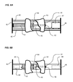
- FIG. 8 a is an exemplary diagram showing the top view of a first variation of an improved Pilates apparatus.
- FIG. 8 b is an exemplary diagram showing the top view of a second variation of an improved Pilates apparatus.
- FIG. 9 is an exemplary diagram showing the operation one variation of a system to automatically increase or decrease exercise resistance in real-time during exercise an improved Pilates apparatus.
- an exercise machine adjustable resistance system and method which comprises a control unit in communication with a resistance adjustment system of an exercise machine and a biometric monitoring device used by an exerciser on the exercise machine.
- the control unit receives biometric data from the biometric monitoring device and sends a control signal to the resistance adjustment system to adjust the resistance of the exercise machine based on the biometric data received.
- the resistance of the exercise machine may be adjusted by increasing or decreasing the resistance of a resistance device 3 and/or by increasing or decreasing the incline of the exercise machine with respect to a base (e.g. horizontally align the exercise machine for limited resistance and inclined upwardly from a first end to a second end of the exercise machine for increased resistance).
- the increase or decrease of the incline of the exercise machine may be accomplished by one or more actuators that elevate the exercise machine accordingly.
- the exercise machine of the present invention is preferably comprised of a Pilates exercise machine as illustrated in FIGS. 6 through 8 b of the drawings.
- the exercise machine may be comprised of various other types of exercise machines such as, but not limited to, a rowing machine and the like.
- U.S. Pat. No. 7,803,095 to Sebastien Lagree and U.S. Pat. No. 8,641,585 to Sebastien Lagree illustrate exemplary exercise machines suitable for usage herein and are incorporate by reference in their entirety.
- FIG. 1 is an exemplary diagram of a system to electronically control changes in exercise resistance levels of an improved Pilates apparatus.
- an exercise resistance setting control 1 is an input device for a Pilates exercise adjustment system.
- An exerciser (not shown) enters the desired level of resistance against which they want to exercise, the signal from the input resistance setting control thereafter being communicated to a control unit 2 by means of a communication control signal bus 4 .
- the bus 4 may be a wireless or wired communication link between the exercise resistance setting control 1 and control unit 2 .
- the control unit 2 processes the input signal so that a control unit 2 output communicates with an resistance device 3 by means of an adjustment system bus 5 .
- the bus 5 may be a wireless or wired communication link between the control unit 2 and resistance device.
- control unit 2 may perform functions beyond the processing of the input control signal, including for example, referencing a table of resistance settings in a database, performing a time-based analysis of differences in resistance settings, or processing signals for displaying resistance levels on a digital display device.
- FIG. 2 is an exemplary diagram of various systems and methods of inputting a control signal that controls changes in exercise resistance levels of an improved Pilates apparatus.
- an exercise resistance setting control 1 e.g. a control signal processor
- a control unit 2 in communication with a control unit 2 originates a control signal from one of many optional control setting sources 20 .
- Signal origination may be generated by an exerciser interfacing with a manual resistance setting control 21 , for example, an analog dial, or digital input keypad, whereby an exerciser may specify the desired resistance level, typically expressed in pounds or kilograms.
- control signal may originate from a database of resistance settings shown in the drawing as a preprogrammed resistance setting control 22 .
- a database of resistance settings shown in the drawing as a preprogrammed resistance setting control 22 .
- access to a database would require that a query or instruction first be sent to a database, for instance, a “start” instruction.
- start a query or instruction first be sent to a database
- user interface to the database would be required to cause the database to generate a desired control signal.
- a control signal may be caused to be generated by an automatic resistance setting control 23 .
- an exerciser upon the Pilates apparatus may be wearing a heart rate monitor that continually monitors the exerciser's heart rate throughout the exercise period.
- the heart rate monitor may be in wired or wireless communication with the control unit 2 and database previously discussed.
- the signal processor 2 receives a signal indicating that the exerciser's heart rate has changed, the signal processor 2 and database look up the preprogrammed resistance level corresponding to the updated heart rate data, and creates an output signal instructing a resistance level adjustment system to change the resistance level.
- control setting source it is not the intention of the present invention to limit the control setting source to the examples just discussed.
- the manual resistance setting control 21 , preprogrammed resistance setting control 22 , and automatic resistance setting control 23 are shown to illustrate the wade range of methods and devices that may be used to originate a control signal that will cause a resistance adjustment system of the present invention to change the resistance level acting on the slidable carriage of a Pilates apparatus at any time that the resistance adjustment system receives the instruction from the signal processor 2 .
- FIG. 3 is an exemplary diagram of various systems and methods of changing resistance levels in response to a resistance control signal of an improved Pilates apparatus.
- a resistance device 3 e.g. exercise resistance adjustment system
- receives a signal from a processor 2 such signal directing a change in the resistance level setting of an improved Pilates apparatus.
- a plurality of resistance variation means 30 are shown, including but not being limited to an electromechanical latching mechanism 31 , and eddy current brake 32 , a dashpot 33 , and a resistance sensing means 34 .
- the resistance adjustment system 3 may comprise an electromechanically actuated latching mechanism 31 .
- Typical Pilates apparatuses provide for removably attachable springs affixed between a fixed end of the apparatus, and a slidable carriage. Exercisers are currently required to stop exercising, dismount the apparatus, and manually engage or disengage one or more springs between the apparatus structure and slidable carriage, thereby increasing or decreasing the resistance workload against which the exerciser must work.
- the electromechanical latching mechanism 31 of the present invention eliminates the need for an exerciser to manually perform a spring change, and in response to a control signal, automatically actuates a mechanism that latches or unlatches one or more springs between the apparatus structure and slidable carriage.
- the resistance adjustment system 3 may comprise an eddy current brake 32 .
- U.S. Pat. No. 5,031,900 to Leask discloses an Eddy Current Braking System which is incorporated by reference herein.
- a rotating eddy current brake 32 may be preferably used when a method of accelerating the rotational speed of a coil in response to force applied by an exerciser on a slidable carriage is used.
- the slidable carriage may be movably attached to a linear gear, such as a gear rack, interacting with a pinion gear affixed to the rotational shaft of the eddy current brake coil.
- a slow linear movement of the slidable carriage, and correspondingly the gear rack would induce a disproportionately high rotational speed of the coil of the eddy current brake 32 .
- the braking force of an eddy current brake 32 is changed by varying the current passing through electromagnets.
- current changes responsive to one or more control signals received from a control unit 2 during performance of an exercise would change the exerciser's resistance level in real time.
- a rotational shaft strain gauge in communication with the rotational shaft of the eddy current coil may be used to measure the torque applied to the shaft.
- a processor 2 converting torque measurements into resistance measurements would programmatically determine the instant level of resistance acting upon the slidable carriage, and communicate a signal back to the eddy brake 32 to increase or decrease braking force to thereby change the exercise resistance level in real time.
- FIG. 4 is an exemplary diagram showing analog and digital control signal input methods. It is preferable that the system and method of automatically controlling the resistance of an improved Pilates apparatus of the present invention provide a means of inputting a desired resistance level against which to perform an exercise.
- HIIT requires the exerciser to cyclically vary the intensity of their exercise between moderate intensity, to high intensity, back to moderate or even low intensity, throughout an exercise period.
- an runner practicing a HIIT running workout may jog for two minutes, then immediately sprint at a 90 percent of their cardiovascular maximum rate for one minute, then return to jogging for another two minutes, thereafter repeating the cycle until finishing.
- This more efficient exercise method compares to a runner who may run at a 75 percent of cardiovascular capacity through the exercise period.
- an exerciser may create a program, or select a pre-programmed 45 minute long exercise routine 50 providing for a HIIT-based workout.
- a typical Pilates routine may include the performance of more than one exercise in a sequence.
- an exerciser may select a sequence that includes #132 as one exercise number 51 , the actual number attributable to any given exercise being arbitrary, other than a designator to differentiate between exercises.
- a designated workload resistance in pounds 53 is selected for the selected exercise and time, thereby completing the time and intensity criteria for the selected exercise. It should be known that any resistance level, or quantification of resistance, such as pounds or kilograms, may be used without departing from the system and method of the present invention.
- an exerciser on a Pilates apparatus may create an exercise routine that automatically changes the resistance intensity, and the duration of the resistance, for one or more exercises of an exercise routine, without having to stop the routine to manually change resistance settings.
- the exercise workload intensity profile 54 will clearly indicate a variation or exercise intensity throughout the period.
- the workload curve during a routine 55 illustrates a correlation between the workload resistance in pounds, and the performance duration of each exercise performed at the variable workload resistance.
- the increasing and decreasing points on the workload curve represent cyclical changes from moderate to high intensity exercise as prescribed for HIIT exercise routines.
- the tale recommends performance of each exercise in the sequence at certain heart rate levels, including a heart rate of 65% of the exerciser's maximum heart rate 56 for exercise 132 , as compared to lower heart rates for the exercises immediately preceding and succeeding exercise 132 in the exercise sequence.
- the present invention for the first time, provides the advantage of HIIT exercising on an improved Pilates apparatus by automatically changing the exercise workload resistance in real-time, throughout the exercise routine, without the long-accepted tradition of stopping the exercise routine, dismounting the apparatus to manually change spring resistance, remounting the apparatus, and re-starting a new exercise in the exercise routine sequence.
- FIG. 6 is an exemplary diagram showing one variation of a system of automatically modifying the resistance levels of a Pilates apparatus in response to the exerciser's cardiovascular performance level.
- an exerciser 64 moving the slidable carriage 63 connected to the foot end 62 by a plurality of springs 61 of equal spring tension will expend more energy than an exerciser 64 moving the slidable carriage 63 connected to the foot end 62 with only one spring 61 . Therefore, as can readily be realized, by increasing or decreasing the number of springs 61 interconnected between the foot end 62 and slidable carriage 63 , an exerciser 64 will respectively increase or decrease the intensity of the fitness workout.
- the level of intensity with which an exerciser 64 is performing an exercise is reflected in the exerciser's cardiovascular performance, determined in part by heart rate and blood pressure.
- a wearable heart rate monitor 65 the exerciser 64 is provided with real-time cardiovascular performance information.
- the real time heart rate data 66 is shown as 102 beats per minute heart rate, and 122/85 blood pressure.
- the 90% target heart rate and work intensity 68 requires the exerciser's heart rate to reach 162 beats per minute. Referring back to the representative actual heart rate 66 of 102 beats per minute, it can be readily determined that the resistance level of the apparatus must increase in order to force the exerciser to work harder, and therefore increase the heart rate to 162 .
- a wearable heart rate monitor 65 in wired or wireless communication with the electronic resistance adjustment system 3 of the present invention, acts as, or sends a signal to the resistance setting input device not shown.
- the resistance setting input means is in communication with the control unit 2 that will determine the appropriate resistance setting.
- the drawing further illustrates one variation of the control signal processor 2 incorporating a database containing one or more heart rate tables 67 , and more specifically, a heart rate table 67 representing standard heart rate workloads for a 40 year old male.
- the control unit 2 in communication with the heart rate table 67 , determines that the exerciser 64 is working against too low of a resistance force, and communicates a signal 5 to the resistance adjustment system 3 to increase the resistance level of the apparatus 60 .
- the mechanism By actuating one of the previously described mechanisms to automatically adjust the resistance of the Pilates apparatus 60 shown in the drawing, the mechanism will attach one or more additional springs 61 to the slidable carriage 63 , thereby increasing the workload, and subsequently the exerciser's heart rate.
- the wearable heart rate monitor 65 will continually update the control unit 2 of the actual heart rate, and by repeating the process just described, increase or decrease the spring resistance so that the exerciser's heart rate remains at the correct performance level throughout the exercise routine as prescribed by the exerciser's inputted exercise routine program at the beginning of the exercise routine.
- FIG. 7 is an exemplary diagram showing a sequence of illustrations of an exerciser performing multiple repetitions of an exercise upon an improved Pilates apparatus.
- a simplified sequence shows a representative exerciser 64 performing an exercise upon an improved Pilates apparatus 60 comprising a stationary foot end 62 , a slidable carriage 63 and one or more resistance springs 61 removably attachable between the foot end 62 and slidable carriage 63 .
- the heart rate data at rest 70 which reflects real-time data received from a wearable heart rate monitor 65 is displayed on a display screen of an improved Pilates apparatus 60 before the exerciser 64 begins exercising.
- STEP 2 shows the exerciser 64 after having completed the primary work cycle of the first repetition of ten cycles by exerting a force F 1 against the existing resistance setting of the apparatus.
- the exerciser's heart rate has increased by 4 beats per minute compared to the resting heart rate 70 .
- the wearable heart rate monitor 65 being in communication with the electronically adjustable resistance system and method of the present invention as previously described, but not shown, immediately determines the heart rate data at rest after first cycle 72 as 110 beats per minute, confirming that increased workload is immediately required in order to quickly get the exerciser's performance up to a higher targeted heart rate.
- the resistance device 3 responds by attaching one or more additional springs 73 between the foot end 62 of the apparatus 60 and the slidable carriage 63 .
- STEP 4 shows the exerciser 64 completing the primary workload cycle of the second cycle, this time exerting a higher force F 2 against the increased resistance created by the addition of spring tension just described.
- the display of the heart rate data during second cycle 74 shows that the exerciser's heart rate has increased to 122 beats per minute in response to the automatically increased workload.
- FIGS. 8 a and 8 b are exemplary drawings showing the top view of two variations of an improved Pilates apparatus.
- the electronically adjustable resistance system 3 and method of the present invention may comprise various electrical, electronic, electromechanical, electromagnetic, and mechanical devices, systems and components not used in traditional Pilates apparatuses. Therefore, accommodations to incorporate the additional components into an improved Pilates apparatus must be reasonably made.
- An spring assembly docking station 84 is shown affixed to the stationary structure, by means of pull knobs of idle spring assemblies 83 , retaining two springs 61 not currently latched to the slidable carriage.
- An resistance device 3 in response to a signal from a control unit 2 (not shown), provides for latching the pull knobs of one or more idle spring assemblies 83 to the spring assembly catch 81 , thereby increasing the resistance force on the slidable carriage 63 , and alternatively, in response to a signal from a control unit 2 (not shown), provides for unlatching the pull knobs of one or more pull knobs of engaged spring assembly 82 , thereby decreasing the resistance force on the slidable carriage 63 .
- a component housing 87 is affixed to the structure of a traditional Pilates apparatus 60 , the housing 87 containing various components as just described as may be required for any variation of an electronically adjustable resistance system and method of the present invention.
- the parallel rails 80 are replaced by an enclosed monorail support for a slidable carriage 85 , the enclosed monorail thereby enclosing one or more resistance springs 61 , a spring assembly docking station 84 retaining the pull knobs of one or more idle spring assemblies 83 , and one or more pull knobs of engaged spring assemblies 82 latched to the springs assembly latch 81 .
- resistance springs 61 is not meant to be limiting, and the enclosed monorail support may house a dashpot 33 , eddy current brake 32 , or other known means of variably creating a resistance force upon the slidable carriage 63 of a Pilates apparatus 60 .
- Such components and systems may be mounted and enclosed within the enclosed monorail support for a slidable carriage 85 .
- possible component mounting areas 88 provide for the efficient placement of a plurality of components, including at the opposed ends of the structure of the improved Pilates apparatus 60 .
- the various resistance inducing means previously described require the use of one or more electrical wires, high pressure hydraulic hoses or plumbing which may be required to traverse substantially the length of the apparatus.
- FIG. 9 is an exemplary diagram showing the operation one variation of a system to automatically increase or decrease exercise resistance in real-time during exercise an improved Pilates apparatus.
- the drawing illustrates, in four simplified steps, one example of one process of automatically latching a resistance spring assembly between a stationary Pilates structure, and a slidable carriage mounted thereupon.
- a slidable carriage 63 is moved along sliding rails or a monorail. As can be seen, there are no spring assemblies latched to the springs assembly latch 81 , and correspondingly no resistance force is applied to the slidable carriage 63 .
- a spring 61 and pull knob 83 together comprising an unlatched, and therefore “idle” spring assembly, is retained by an idle spring assembly carrier 90 affixed to a docking station support structure 93 by means of an axle not shown at the carrier pivoting means 92 , and an actuator 91 (e.g. a carrier lifting solenoid).
- the slidable carriage 63 is being moved linearly in a direction towards the fixed end of the apparatus 60 (not shown).
- control unit 2 in response to a resistance control signal input device (not shown), the control unit 2 communicates a control signal through a bus 5 or wirelessly to a receiver that thereby actuates the actuator 91 , pivoting the carrier 90 about the pivoting means 92 , until the foot end side of the pull knob is in communication head end surfaces of both the idle spring carrier 90 and the springs assembly latch 81 .
- the lifting of the carrier 90 into a position so that the transfer of the spring assembly from the carrier 90 to the springs assembly latch 81 can be practically instantaneous.
- resistance is used herein to mean a weight equivalent force that an exerciser upon a Pilates apparatus must overcome in order to move a slidable carriage in a direction opposite to the direction of the force.
- Resistance in an exercise apparatus may be created by use of springs (including elastic bands, metal springs, plastic springs), viscous fluid dampeners, eddy current brakes, friction blocks, or a variety of other electrical, electromechanical, hydraulic, electromagnetic means well known to those skilled in the art. It is not the objective of the present invention to be limited to known systems or methods of creating a resistance force, but rather to teach a novel method of controlling the resistance force change in an improved Pilates apparatus.
- Control circuits are well known to those skilled in the art. It should be noted that it is not the objective of the present invention to limit the architecture or function of a control system of any particular control system design or method, but rather to broadly describe the applicability of control systems when used to change the exercise resistance level of a Pilates apparatus during the performance of an exercise. The broadest interpretation should be given to control systems as they may apply to controlling a variable resistance in an Pilates apparatus.
Abstract
An exercise machine adjustable resistance system and method for efficiently varying the workout resistance for an exercise machine. The exercise machine adjustable resistance system and method generally includes a control unit in communication with a resistance adjustment system of an exercise machine and a biometric monitoring device used by an exerciser on the exercise machine. The control unit receives biometric data from the biometric monitoring device and sends a control signal to the resistance adjustment system to adjust the resistance of the exercise machine based on the biometric data received.
Description
The present application is a continuation of U.S. application Ser. No. 14/742,144 filed on Jun. 17, 2015 which issues on Mar. 7, 2017 as U.S. Pat. No. 9,586,089, which claims priority to U.S. Provisional Application No. 62/013,032 filed Jun. 17, 2014. Each of the aforementioned patent applications, and any applications related thereto, is herein incorporated by reference in their entirety.
Not applicable to this application.
Field of the Invention
The present invention relates generally to an exercise machine and more specifically it relates to an exercise machine adjustable resistance system and method for efficiently varying the workout resistance for an exercise machine.
Description of the Related Art
Any discussion of the related art throughout the specification should in no way be considered as an admission that such related art is widely known or forms part of common general knowledge in the field.
Contemporary Pilates apparatuses are well known throughout the fitness industry, and are generally comprised of a rectangular frame supported on the floor at various points of contact about the rectangular frame.
The base structure of a Pilates apparatus supports an upper structure comprised of two parallel rails aligned with the major length axis of the rectangular structure, and a slidable carriage thereupon that is attached to one end of the structure by springs or elastic bands that produce a resistance bias on the slidable carriage.
Exercises are performed by an exerciser by moving the slidable carriage along the rails in a direction distal to the end of the apparatus to which the fixed end of the resistance springs are attached. One or more resistance springs create a workload against which therapeutic or fitness exercises can be safely and beneficially performed.
Traditional Pilates apparatuses typically provide for a plurality of spring assemblies that may be removably attached between the slidable carriage and the fixed end, with each spring being of a specified design to deliver a known force. As an example, six resistance springs, each delivering a constant K-factor of 15 pounds, may be installed on an apparatus. An exerciser therefore would engage one of the springs in order to perform arm exercises against a 15 pound resistance force.
When the exerciser changes exercises to leg exercises, the exerciser must engage a multitude of additional springs since the 15 pound force would be inadequate resistance to apply an effective exercise workload resistance to the much larger leg muscles. Therefore, the exerciser may manually “hook up” or engage an additional three springs to create a total workload resistance of 60 pounds.
This process of engaging and disengaging one or more springs to vary the workout resistance force throughout a typical Pilates workout comprised of multiple exercises has been practiced since the invention of the first Pilates apparatus nearly a century ago, and is well known to those skilled in the art.
One major deficiency of the resistance-changing process of contemporary Pilates apparatuses is that the process is time-consuming. Pilates classes are typically delivered during a fixed period of time to a group of exercisers, each exercising on their respective apparatuses. It is important for all exercisers to start each of the many exercises together, and at the command of the Pilates instructor. As the instructor calls for a change in exercise, all exercisers must stop, usually dismount the apparatus, quickly change resistance by engaging or disengaging the correct springs, re-mount the apparatus, and ready themselves for the next exercise.
Exercisers with high experience will know what springs to engage or disengage, and do so quickly. Inexperienced exercisers will struggle with the mechanics of changing springs, and will not fully understand color coding related to springs of different K-factors, nor which of the springs to engage or disengage. The inexperienced exerciser will require the personalized assistance of an instructor or fellow exerciser.
As can readily be seen, the act of changing springs between exercises can cause considerable disruption and time delay, significantly diminishing the available workout time available within the time limits of fixed duration class.
Another disadvantage of the traditional spring-changing process is that exercisers are unable to quickly change resistance settings to intensify the workload effort of a given exercise. For instance, at the start of an exercise period, an exerciser would typically “warm up” by performing a number of repetitions of a certain exercise against a comparatively light resistance force. After a few minutes of warming up the working muscles, it would be preferable to increase the resistance to intensify the exercise effort. Traditional Pilates apparatuses do not provide the capability to change the resistance force during the performance of an exercise, and require the exerciser to stop and manually change springs as previously described.
Another disadvantage of contemporary Pilates apparatuses is that exercisers oftentimes simply don't know the appropriate resistance setting for a particular exercise, and inadvertently select too high, or too low of a workload resistance at the start. If the workload resistance is too low, they stop after one or two repetitions, and re-set the springs to a higher workload.
On the other hand, if the set a starting workload resistance that is too high, the exerciser risks injury from overstressing muscles required to overcome the overly high spring resistance force the initially set.
Another disadvantage of contemporary Pilates apparatuses is that all spring settings must be manually adjusted. It is well known in the fitness industry that instructors, throughout the exercise period, frequently instruct the class to change exercises, to increase or decrease the speed at which they should perform the exercises, and change workload levels against which the exercise should be performed. There is presently no ability for an instructor to simultaneously change the workload intensity of all apparatuses of all exercisers in the class. This disadvantage results in a less beneficial workout for the exercisers who otherwise would realize a more intense exercise period.
Yet another significant disadvantage of traditional Pilates apparatuses is the inability of an exerciser to consistently work within a specified cardiovascular performance range. It is well known to those killed in the art of fitness training that exercisers benefit most during an exercise period when the workload intensity throughout the period begins low, ramps up significantly over a period of time, then tapers off as the end of the workout period approaches. During the high intensity period, exercisers may work at 90 percent of their recommended cardiovascular capacity.
Wearable digital activity tracking devices are well known, and are capable of determining an exerciser's cardiovascular levels in real time. As an example, a bicyclist monitoring their performance can use a wearable activity tracking device to determine that they are only working at 50% capacity, and in response, pedal harder until the device indicates that they are working at an 85% capacity.
Unfortunately, even if a Pilates exerciser is using a wearable activity tracking device, Pilates apparatuses all require the exerciser to stop and manually change spring resistance changes in order to intensify workload, thereby disrupting the flow of the exercise routine. Additionally, the stop-and-go process allows the cardiovascular system to momentarily recover, negating many of the physiological benefits realized by continually ramping resistance throughout an exercise routine, thereby continually increasing cardiovascular capacity.
Therefore, those skilled in the art would recognize the significant advantages of a new and novel Pilates apparatus providing for increasing or decreasing workout resistance on demand, and in real-time, without requiring the exerciser to stop the exercise, thereby overcoming the deficiencies of contemporary Pilates apparatuses requiring exercisers to manually change resistance settings.
It will be further appreciated by those skilled in the art that a Pilates apparatus as described would save resistance change-over time during an exercise class, and to the exerciser's delight, allocating more time to beneficial exercise. Delivering more fitness benefits to customers within a given time period is of significant commercial value.
Because of the inherent problems with the related art, there is a need for a new and improved exercise machine adjustable resistance system and method for efficiently varying the workout resistance for an exercise machine.
Provided herein is an exercise machine which includes a control unit in communication with a resistance adjustment system of an exercise machine and a biometric monitoring device used by an exerciser on the exercise machine. The control unit receives biometric data from the biometric monitoring device and sends a control signal to the resistance adjustment system to adjust the resistance of the exercise machine based on the biometric data received.
There has thus been outlined, rather broadly, some of the features of the invention in order that the detailed description thereof may be better understood, and in order that the present contribution to the art may be better appreciated. There are additional features of the invention that will be described hereinafter and that will form the subject matter of the claims appended hereto. In this respect, before explaining at least one embodiment of the invention in detail, it is to be understood that the invention is not limited in its application to the details of construction or to the arrangements of the components set forth in the following description or illustrated in the drawings. The invention is capable of other embodiments and of being practiced and carried out in various ways. Also, it is to be understood that the phraseology and terminology employed herein are for the purpose of the description and should not be regarded as limiting.
Various other objects, features and attendant advantages of the present invention will become fully appreciated as the same becomes better understood when considered in conjunction with the accompanying drawings, in which like reference characters designate the same or similar parts throughout the several views, and wherein:
Provided herein is an exercise machine adjustable resistance system and method, which comprises a control unit in communication with a resistance adjustment system of an exercise machine and a biometric monitoring device used by an exerciser on the exercise machine. The control unit receives biometric data from the biometric monitoring device and sends a control signal to the resistance adjustment system to adjust the resistance of the exercise machine based on the biometric data received. The resistance of the exercise machine may be adjusted by increasing or decreasing the resistance of a resistance device 3 and/or by increasing or decreasing the incline of the exercise machine with respect to a base (e.g. horizontally align the exercise machine for limited resistance and inclined upwardly from a first end to a second end of the exercise machine for increased resistance). The increase or decrease of the incline of the exercise machine may be accomplished by one or more actuators that elevate the exercise machine accordingly.
The exercise machine of the present invention is preferably comprised of a Pilates exercise machine as illustrated in FIGS. 6 through 8 b of the drawings. However, the exercise machine may be comprised of various other types of exercise machines such as, but not limited to, a rowing machine and the like. U.S. Pat. No. 7,803,095 to Sebastien Lagree and U.S. Pat. No. 8,641,585 to Sebastien Lagree illustrate exemplary exercise machines suitable for usage herein and are incorporate by reference in their entirety.
It should be noted that the control unit 2 may perform functions beyond the processing of the input control signal, including for example, referencing a table of resistance settings in a database, performing a time-based analysis of differences in resistance settings, or processing signals for displaying resistance levels on a digital display device.
Further, the control signal may originate from a database of resistance settings shown in the drawing as a preprogrammed resistance setting control 22. Those skilled in the art will appreciate that access to a database would require that a query or instruction first be sent to a database, for instance, a “start” instruction. Although not shown, it would also be well known that a user interface to the database would be required to cause the database to generate a desired control signal.
Still further, a control signal may be caused to be generated by an automatic resistance setting control 23. For example, an exerciser upon the Pilates apparatus may be wearing a heart rate monitor that continually monitors the exerciser's heart rate throughout the exercise period. Although not shown, the heart rate monitor may be in wired or wireless communication with the control unit 2 and database previously discussed. As the signal processor 2 receives a signal indicating that the exerciser's heart rate has changed, the signal processor 2 and database look up the preprogrammed resistance level corresponding to the updated heart rate data, and creates an output signal instructing a resistance level adjustment system to change the resistance level.
It is not the intention of the present invention to limit the control setting source to the examples just discussed. By way of example, the manual resistance setting control 21, preprogrammed resistance setting control 22, and automatic resistance setting control 23, are shown to illustrate the wade range of methods and devices that may be used to originate a control signal that will cause a resistance adjustment system of the present invention to change the resistance level acting on the slidable carriage of a Pilates apparatus at any time that the resistance adjustment system receives the instruction from the signal processor 2.
In the first example, the resistance adjustment system 3 may comprise an electromechanically actuated latching mechanism 31. Typical Pilates apparatuses provide for removably attachable springs affixed between a fixed end of the apparatus, and a slidable carriage. Exercisers are currently required to stop exercising, dismount the apparatus, and manually engage or disengage one or more springs between the apparatus structure and slidable carriage, thereby increasing or decreasing the resistance workload against which the exerciser must work. The electromechanical latching mechanism 31 of the present invention eliminates the need for an exerciser to manually perform a spring change, and in response to a control signal, automatically actuates a mechanism that latches or unlatches one or more springs between the apparatus structure and slidable carriage. Those skilled in the art will appreciate that a great number of electrically actuated mechanical devices may be used to latch or unlatch a spring from a slidable carriage, including cams, lifters, collets, and other well-known mechanisms. The disclosure of an electromechanical latching and unlatching mechanism is not meant to be limiting, but by way of example, the mechanisms just described illustrate variations of the automatic latching and unlatching system responsive to a control signal of the present invention.
As a second example, the resistance adjustment system 3 may comprise an eddy current brake 32. The use of eddy current brakes 32 in exercise equipment, and specifically on stationary bicycles, is well known. However, eddy current brakes 32 have never before been applied to Pilates apparatuses. Eddy current brakes 32 operate by creating eddy currents through an electromagnetic induction rotor, thereby creating resistance on a coil rotated at high speed between the plates of the rotor. Eddy current brakes 32 may be of a linear structure where a magnetic yolk is used in place of a rotor, and electrical coils located along the length of a rail. U.S. Pat. No. 5,031,900 to Leask discloses an Eddy Current Braking System which is incorporated by reference herein.
One problem with an eddy current brake 32 is that they are generally inefficient at low speeds. Therefore, in the present invention, a rotating eddy current brake 32 may be preferably used when a method of accelerating the rotational speed of a coil in response to force applied by an exerciser on a slidable carriage is used. For example, the slidable carriage may be movably attached to a linear gear, such as a gear rack, interacting with a pinion gear affixed to the rotational shaft of the eddy current brake coil. In such a configuration, a slow linear movement of the slidable carriage, and correspondingly the gear rack, would induce a disproportionately high rotational speed of the coil of the eddy current brake 32.
The braking force of an eddy current brake 32 is changed by varying the current passing through electromagnets. When applied to a novel Pilates apparatus, current changes responsive to one or more control signals received from a control unit 2 during performance of an exercise would change the exerciser's resistance level in real time.
As a third example, variable resistance to a linear exercise force in a Pilates apparatus may be created using a dashpot 33. A dashpot 33 is a term used by those skilled in the art to describe a damper which resists linear motion via friction of a viscous fluid damper, for instance, an hydraulic cylinder. A dashpot 33 generally comprises a cylindrical housing, a piston positioned therein, and a viscous fluid that is moved from one side of the piston to the other through a canal at a controlled velocity proportional to the linear force exerted on the piston ram. The proportional resistance force created by a dashpot 33 acts in a direction opposite to the force and force velocity applied to it. For instance, a dashpot 33 affixed between a stationary end of a Pilates apparatus, and the slidable carriage, would resist the force an exerciser applied to the slidable carriage in a direction opposite to the fixed end of the dashpot 33. The resistance force of the dashpot 33 created by viscous friction may be varied by regulating the size of an orifice, or valve opening, through which the viscous fluid transfers from one side of the piston to the other.
In the present invention, a valve control signal received from the control unit 2 would instruct the valve to open, thereby reducing the friction and resistance level, or to close, thereby increasing the resistance level. Dashpots 33 provide for smooth operation throughout the fluid transfer cycle, an added benefit in Pilates apparatuses that are well known for allowing exercisers to exercise using smooth, low impact motion.
It should be noted that it is not the intention to require the use of ordinary or well known devices or systems just described, nor to limit the use of any these or other known systems or mechanisms to vary exercise resistance in an improved Pilates apparatus, but rather to apply the use of well known resistance control means in response to the resistance control signal of the present invention, thereby causing a real-time resistance change of a Pilates apparatus at any time the control signal is received by the resistance-changing device.
Further, one or more resistance sensing means 34, may be used to measure the resistance force created by the resistance force means, and communicate the level of resistance force to a processor 2 for analysis to determine any required increase or decrease adjustment desired. As an example, a pressure sensor on a dashpot 33 would measure the force applied to the piston, communicating the force level to a processor 2 for analysis of the actual force against the intended force. Thereafter, the processor 2 will send an “open” or “close” signal to the friction valve as a means of respectively decreasing or increasing the resistance level to more closely match the intended resistance level.
Referring to a previously described example of the use of a rotational eddy current brake 32, a rotational shaft strain gauge in communication with the rotational shaft of the eddy current coil may be used to measure the torque applied to the shaft. A processor 2 converting torque measurements into resistance measurements would programmatically determine the instant level of resistance acting upon the slidable carriage, and communicate a signal back to the eddy brake 32 to increase or decrease braking force to thereby change the exercise resistance level in real time.
Such inputting means may be an analog dial 40, otherwise known to those skilled in the art as an analog electronic dial controller. Analog dials 40 may be indicating, or non-indicating. A non-indicating dial is an inputting device allowing an exerciser to turn the dial to the desires resistance setting without feedback of the actual resistance that has been set, or an indicating dial that receives a signal back from the resistance setting means indicating the actual resistance setting, thereby allowing an exerciser to modify the setting until the desired resistance setting is actually realized.
A digital resistance setting keypad 41, also often referred to as a controller keypad, may be used by an exerciser to input an exercise resistance selection into an improved Pilates apparatus providing for real-time changing of the exercise resistance level of the apparatus at any time throughout the exercise cycle. Controller keypads may use analog keys for inputting a selection, or may incorporate various touch screen technologies to allow for the inputting of one or more resistance settings.
Controller keypads may be non-indicating, meaning that the keypad lacks a display means to indicate the actual resistance setting back to the exerciser after inputting the resistance selection. An indicating keypad may provide for audible or visual information feedback via one or more speakers, or one or more display screens.
The many variations of electronic circuits used in indicating and non-indicating analog dials and controller keypads are well known, and it not the intention of the present invention to require the use of any specific circuit or signal processing means, but rather to illustrate that an analog electronic dial or keypad controllers may be reasonably used as the input device by which an exerciser may input the desired resistance setting of an improved Pilates apparatus.
Exercisers exercising on contemporary Pilates apparatuses are currently provided no method of automatically changing the exercise resistance levels during an exercise sequence performed on a Pilates apparatus. On the other hand, it is well known in the fitness industry that high intensity interval training, often referred to as “HIIT”, accelerates weight loss, and increases metabolic function for a longer period of time after completion of an exercise routine.
HIIT requires the exerciser to cyclically vary the intensity of their exercise between moderate intensity, to high intensity, back to moderate or even low intensity, throughout an exercise period. As an example, an runner practicing a HIIT running workout may jog for two minutes, then immediately sprint at a 90 percent of their cardiovascular maximum rate for one minute, then return to jogging for another two minutes, thereafter repeating the cycle until finishing. This more efficient exercise method compares to a runner who may run at a 75 percent of cardiovascular capacity through the exercise period.
Despite the overwhelming body of work validating the advantages of HIIT, the ability of structuring a HIIT routine based on varying the exercise resistance level in real-time, throughout the performance of an exercise routine, has never before been possible on contemporary Pilates apparatuses.
In the drawing, an exerciser may create a program, or select a pre-programmed 45 minute long exercise routine 50 providing for a HIIT-based workout. A typical Pilates routine may include the performance of more than one exercise in a sequence. In a database table containing a list of different Pilates exercises, an exerciser may select a sequence that includes #132 as one exercise number 51, the actual number attributable to any given exercise being arbitrary, other than a designator to differentiate between exercises.
Further, the exerciser may select a time duration 52 (e.g. seconds, minutes, hours) during which to perform the exercise. It should be known that any time duration, or quantification of time, such as seconds or minutes may be used without departing from the system and method of the present invention.
Still further, a designated workload resistance in pounds 53 is selected for the selected exercise and time, thereby completing the time and intensity criteria for the selected exercise. It should be known that any resistance level, or quantification of resistance, such as pounds or kilograms, may be used without departing from the system and method of the present invention.
By continuing the process for inputting exercise, duration and resistance level as just described for additional exercises to be performed during the 45 minute exercise routine, an exerciser on a Pilates apparatus, for the first time, may create an exercise routine that automatically changes the resistance intensity, and the duration of the resistance, for one or more exercises of an exercise routine, without having to stop the routine to manually change resistance settings.
When considering the 45 minute exercise period as a whole, the exercise workload intensity profile 54 will clearly indicate a variation or exercise intensity throughout the period. The workload curve during a routine 55 illustrates a correlation between the workload resistance in pounds, and the performance duration of each exercise performed at the variable workload resistance. The increasing and decreasing points on the workload curve represent cyclical changes from moderate to high intensity exercise as prescribed for HIIT exercise routines.
As is shown in the fourth column, the tale recommends performance of each exercise in the sequence at certain heart rate levels, including a heart rate of 65% of the exerciser's maximum heart rate 56 for exercise 132, as compared to lower heart rates for the exercises immediately preceding and succeeding exercise 132 in the exercise sequence.
Therefore, the present invention, for the first time, provides the advantage of HIIT exercising on an improved Pilates apparatus by automatically changing the exercise workload resistance in real-time, throughout the exercise routine, without the long-accepted tradition of stopping the exercise routine, dismounting the apparatus to manually change spring resistance, remounting the apparatus, and re-starting a new exercise in the exercise routine sequence.
In the drawing, a representative exerciser 64 is shown performing an exercise upon a Pilates apparatus 60. The apparatus 60 comprises a substantially stationary structure with a foot end 62, a slidable carriage 63, and one or more resistance springs 61 removably connected between the stationary foot end 62 and slidable carriage 63. The exerciser 64 performs the exercise by using muscle force to overcome the force of the resistance springs 61, thereby moving the slidable carriage in a direction opposite from the foot end 62.
As would be appreciated by those skilled in the art, an exerciser 64 moving the slidable carriage 63 connected to the foot end 62 by a plurality of springs 61 of equal spring tension will expend more energy than an exerciser 64 moving the slidable carriage 63 connected to the foot end 62 with only one spring 61. Therefore, as can readily be realized, by increasing or decreasing the number of springs 61 interconnected between the foot end 62 and slidable carriage 63, an exerciser 64 will respectively increase or decrease the intensity of the fitness workout.
The level of intensity with which an exerciser 64 is performing an exercise is reflected in the exerciser's cardiovascular performance, determined in part by heart rate and blood pressure. By means of a wearable heart rate monitor 65, the exerciser 64 is provided with real-time cardiovascular performance information. In the drawing, the real time heart rate data 66 is shown as 102 beats per minute heart rate, and 122/85 blood pressure.
As a reference point, the maximum heart rate for an individual, and therefore generally considered by those skilled in the art to be equivalent to 100% of an exerciser's heart rate, is often determined by subtracting the exerciser's age from the number 220. Therefore, if the representative exerciser 64 is a 40 year old male, his maximum heart rate could be determined by the formula (220−40)=100% heart rate. The maximum heart rate would therefore be approximately 180 beats per minute.
As can be seen in the heart rate table 67, representative of a heart rate table for a 40 year old male, the 90% target heart rate and work intensity 68 requires the exerciser's heart rate to reach 162 beats per minute. Referring back to the representative actual heart rate 66 of 102 beats per minute, it can be readily determined that the resistance level of the apparatus must increase in order to force the exerciser to work harder, and therefore increase the heart rate to 162.
In the drawing, a wearable heart rate monitor 65 in wired or wireless communication with the electronic resistance adjustment system 3 of the present invention, acts as, or sends a signal to the resistance setting input device not shown. As previously described, the resistance setting input means is in communication with the control unit 2 that will determine the appropriate resistance setting.
The drawing further illustrates one variation of the control signal processor 2 incorporating a database containing one or more heart rate tables 67, and more specifically, a heart rate table 67 representing standard heart rate workloads for a 40 year old male.
Having previously entered, or selected an exercise routine as described in FIG. 5 , with the recommended 90% of maximum heart rate selected for the instant exercise being performed by the representative exerciser 64, the control unit 2, in communication with the heart rate table 67, determines that the exerciser 64 is working against too low of a resistance force, and communicates a signal 5 to the resistance adjustment system 3 to increase the resistance level of the apparatus 60.
By actuating one of the previously described mechanisms to automatically adjust the resistance of the Pilates apparatus 60 shown in the drawing, the mechanism will attach one or more additional springs 61 to the slidable carriage 63, thereby increasing the workload, and subsequently the exerciser's heart rate.
In real-time, the wearable heart rate monitor 65 will continually update the control unit 2 of the actual heart rate, and by repeating the process just described, increase or decrease the spring resistance so that the exerciser's heart rate remains at the correct performance level throughout the exercise routine as prescribed by the exerciser's inputted exercise routine program at the beginning of the exercise routine.
In the sequence, a simplified sequence shows a representative exerciser 64 performing an exercise upon an improved Pilates apparatus 60 comprising a stationary foot end 62, a slidable carriage 63 and one or more resistance springs 61 removably attachable between the foot end 62 and slidable carriage 63.
In STEP 1, the heart rate data at rest 70 which reflects real-time data received from a wearable heart rate monitor 65 is displayed on a display screen of an improved Pilates apparatus 60 before the exerciser 64 begins exercising.
In STEP 3, at the end of the first cycle, the exerciser 64 momentarily stops exercising while transitioning from moving in a direction towards the foot end 62, to moving away from the foot end 62 to start the second cycle of the ten cycles.
The wearable heart rate monitor 65, being in communication with the electronically adjustable resistance system and method of the present invention as previously described, but not shown, immediately determines the heart rate data at rest after first cycle 72 as 110 beats per minute, confirming that increased workload is immediately required in order to quickly get the exerciser's performance up to a higher targeted heart rate. The resistance device 3 responds by attaching one or more additional springs 73 between the foot end 62 of the apparatus 60 and the slidable carriage 63.
Therefore, but understanding the process as generally described in the foregoing sequence, it can be readily appreciated that the new and novel system and method of automatically changing the resistance setting of a Pilates apparatus provides the benefit of establishing and maintaining preferred heart rates corresponding to targeted variable intensity exercises throughout an exercise routine that were never before possible.
In the top drawing, two parallel sliding rails 80 extend substantially the longitudinal dimension of a Pilates apparatus 60 between the foot end 62 and head end 86. A cut-away top view of a slidable carriage 63 with a spring assembly latch 81 affixed thereto is shown with the pull knobs of engaged spring assemblies 82 removably latched to the springs assembly latch 81.
An spring assembly docking station 84 is shown affixed to the stationary structure, by means of pull knobs of idle spring assemblies 83, retaining two springs 61 not currently latched to the slidable carriage.
An resistance device 3, in response to a signal from a control unit 2 (not shown), provides for latching the pull knobs of one or more idle spring assemblies 83 to the spring assembly catch 81, thereby increasing the resistance force on the slidable carriage 63, and alternatively, in response to a signal from a control unit 2 (not shown), provides for unlatching the pull knobs of one or more pull knobs of engaged spring assembly 82, thereby decreasing the resistance force on the slidable carriage 63.
A component housing 87 is affixed to the structure of a traditional Pilates apparatus 60, the housing 87 containing various components as just described as may be required for any variation of an electronically adjustable resistance system and method of the present invention.
Those skilled in the art will appreciate the importance of minimizing exerciser contact with any of the operational components of an electronically adjustable resistance system thereby minimizing risk of injury to the exerciser 64, as well as minimizing the potential for an exerciser 64 to damage any of the operational components of the system. Therefore, it is preferable to fully enclose as much of the communication, electrical, control, processor and resistance changing means as practicable.
In a variation of an improved Pilates apparatus 60, in the lower drawing, the parallel rails 80 are replaced by an enclosed monorail support for a slidable carriage 85, the enclosed monorail thereby enclosing one or more resistance springs 61, a spring assembly docking station 84 retaining the pull knobs of one or more idle spring assemblies 83, and one or more pull knobs of engaged spring assemblies 82 latched to the springs assembly latch 81.
It should be noted that disclosure of resistance springs 61 is not meant to be limiting, and the enclosed monorail support may house a dashpot 33, eddy current brake 32, or other known means of variably creating a resistance force upon the slidable carriage 63 of a Pilates apparatus 60.
Now, understanding the plurality of components and systems required of the present invention, such components and systems may be mounted and enclosed within the enclosed monorail support for a slidable carriage 85. In FIG. 8b , possible component mounting areas 88 provide for the efficient placement of a plurality of components, including at the opposed ends of the structure of the improved Pilates apparatus 60. More notably, the various resistance inducing means previously described require the use of one or more electrical wires, high pressure hydraulic hoses or plumbing which may be required to traverse substantially the length of the apparatus.
As can be appreciated, running wires, plumbing or hoses substantially the length of a traditional Pilates apparatus 60 would necessarily expose the wires, plumbing or hoses to damage.
Therefore, the advantages of a monorail enclosure to house all of the components of an electronically adjustable resistance system can be immediately recognized by those skilled in the art, and readily appreciated by exercisers 64 using the improved apparatus 60.
More specifically, the drawing illustrates, in four simplified steps, one example of one process of automatically latching a resistance spring assembly between a stationary Pilates structure, and a slidable carriage mounted thereupon.
In STEP 1, a slidable carriage 63 is moved along sliding rails or a monorail. As can be seen, there are no spring assemblies latched to the springs assembly latch 81, and correspondingly no resistance force is applied to the slidable carriage 63. A spring 61 and pull knob 83, together comprising an unlatched, and therefore “idle” spring assembly, is retained by an idle spring assembly carrier 90 affixed to a docking station support structure 93 by means of an axle not shown at the carrier pivoting means 92, and an actuator 91 (e.g. a carrier lifting solenoid). In the drawing, the slidable carriage 63 is being moved linearly in a direction towards the fixed end of the apparatus 60 (not shown).
In STEP 2, the slidable carriage 63 having been moved until it stops with the springs assembly latch 81 being substantially aligned above the idle spring carrier 90, the substantially vertically aligned relationship between the latch 81 and carrier 90 thereby providing for the transfer of the spring assembly from its idle position, to an active position affixed to the assembly latch of the slidable carriage 63.
In STEP 3, in response to a resistance control signal input device (not shown), the control unit 2 communicates a control signal through a bus 5 or wirelessly to a receiver that thereby actuates the actuator 91, pivoting the carrier 90 about the pivoting means 92, until the foot end side of the pull knob is in communication head end surfaces of both the idle spring carrier 90 and the springs assembly latch 81. The lifting of the carrier 90 into a position so that the transfer of the spring assembly from the carrier 90 to the springs assembly latch 81 can be practically instantaneous.
Now, in STEP 4, it can readily be seen that as the slidable carriage 63 moves in a direction opposite from the foot end 62 of the apparatus 60, retention of the pull knob of engaged spring assembly 82 is made by the spring assembly catch of the slidable carriage 63, thereby transferring the force of the spring resistance from the idle spring assembly carrier 90 to the slidable carriage 63.
Further, in response to a control signal 5 from a control unit 2, the actuator 91 lowers the idle spring carrier 90 until such time as a subsequent signal instructs the carrier 90 to lift in order to remove the pull knob 83 from the springs assembly latch 81, thereby reducing the resistance force on the slidable carriage 63.
As will be appreciated by those skilled in the art, the innumerable mechanisms, systems and processes to cause an automatic change of the exercise resistance levels in response to a control input on the improved Pilates apparatus during exercise are not meant to be limiting, and to describe every possible known system or process to accomplish an automatic resistance change would be exhaustive and burdensome, but would nevertheless reinforce the novelty, usefulness and commercial value of the present invention.
Further, it will be appreciated that the electronically adjustable resistance system and method of the present invention, for the first time, provides for more beneficial exercising as a result of eliminating interruptions to an exercise routine to change resistance settings, and more importantly, provides for optimization of the exerciser's exercise time by allowing the exerciser to increase and decrease the HIIT exercise intensity throughout the exercise routine as is well known to those in the fitness industry.
Still further, it will be appreciated by exercisers and Pilates instructors alike, that for the first time, the system and method of the improved Pilates apparatus of the present invention provides for pre-programming different resistances correlating to different Pilates exercises that will be performed in a routine, thereby eliminating the start-stop-re-start sequence between different exercises performed on a traditional Pilates apparatus.
Various aspects of specific embodiments are disclosed in the following description and related drawings. Alternate embodiments may be devised without departing from the spirit or the scope of the present disclosure. Additionally, well-known elements of exemplary embodiments will not be described in detail or will be omitted so as not to obscure relevant details. Further, to facilitate an understanding of the description, a discussion of several terms used herein follows.
The word “exemplary” is used herein to mean “serving as an example, instance, or illustration.” Any embodiment described herein as “exemplary” is not necessarily to be construed as preferred or advantageous over other embodiments. Likewise, the term “embodiments” is not exhaustive and does not require that all embodiments include the discussed feature, advantage or mode of operation.
The word “resistance” is used herein to mean a weight equivalent force that an exerciser upon a Pilates apparatus must overcome in order to move a slidable carriage in a direction opposite to the direction of the force. Resistance in an exercise apparatus may be created by use of springs (including elastic bands, metal springs, plastic springs), viscous fluid dampeners, eddy current brakes, friction blocks, or a variety of other electrical, electromechanical, hydraulic, electromagnetic means well known to those skilled in the art. It is not the objective of the present invention to be limited to known systems or methods of creating a resistance force, but rather to teach a novel method of controlling the resistance force change in an improved Pilates apparatus.
Therefore, as used herein, references may be made to the use of “springs”, “brakes” or other methods just described, with no difference in meaning from “resistance”. The broadest interpretation of “resistance” inducing methods should be made.
Control circuits are well known to those skilled in the art. It should be noted that it is not the objective of the present invention to limit the architecture or function of a control system of any particular control system design or method, but rather to broadly describe the applicability of control systems when used to change the exercise resistance level of a Pilates apparatus during the performance of an exercise. The broadest interpretation should be given to control systems as they may apply to controlling a variable resistance in an Pilates apparatus.
Unless otherwise defined, all technical and scientific terms used herein have the same meaning as commonly understood by one of ordinary skill in the art to which this invention belongs. Although methods and materials similar to or equivalent to those described herein can be used in the practice or testing of the present invention, suitable methods and materials are described above. All publications, patent applications, patents, and other references mentioned herein are incorporated by reference in their entirety to the extent allowed by applicable law and regulations. The present invention may be embodied in other specific forms without departing from the spirit or essential attributes thereof, and it is therefore desired that the present embodiment be considered in all respects as illustrative and not restrictive. Any headings utilized within the description are for convenience only and have no legal or limiting effect.
Claims (20)
1. An exercise machine, comprising:
an exercise machine having a frame, a carriage movable upon the frame and a resistance adjustment device connected to the carriage, wherein the carriage is movable between a first end and a second end of the exercise machine along a longitudinal axis and wherein the resistance adjustment device provides a resistance level to the carriage along at least a first direction of movement of the carriage;
a biometric monitoring device adapted to be connected to an exerciser, wherein the biometric monitoring device is configured to monitor a biometric state of the exerciser; and
a control unit in communication with the resistance adjustment device of the exercise machine and the biometric monitoring device, wherein the control unit receives biometric data from the biometric monitoring device relating to the biometric state of the exerciser and wherein the control unit sends a control signal to the resistance adjustment device to adjust the resistance level of the resistance adjustment device based on the biometric data received;
wherein the resistance adjustment device is comprised of a plurality of resistance devices that are selectively connectable to the carriage, wherein the resistance adjustment device increases a number of the plurality of resistance devices of the resistance adjustment device that are connected to the carriage when the control unit signals an increase in the resistance level and wherein the resistance adjustment device decreases a number of the plurality of resistance devices of the resistance adjustment device that are connected to the carriage when the control unit signals a decrease in the resistance level.
2. The exercise machine of claim 1 , wherein the exercise machine is comprised of a Pilates machine.
3. The exercise machine of claim 1 , wherein the biometric monitoring device is comprised of a heart rate monitor that measures a heart rate of an exerciser.
4. The exercise machine of claim 1 , wherein the control unit automatically changes the resistance level of the resistance adjustment device in real-time throughout the exercise routine to achieve a desired biometric state of the exerciser.
5. The exercise machine of claim 4 , wherein the desired biometric state is comprised of a desired percentage of a maximum heartrate for the exerciser.
6. The exercise machine of claim 5 , wherein the control unit increases the resistance level of the resistance adjustment device if a current heartrate of the exerciser is below the desired percentage of the maximum heartrate for the exerciser.
7. The exercise machine of claim 6 , wherein the control unit decreases the resistance level of the resistance adjustment device if a current heartrate of the exerciser is above the desired percentage of the maximum heartrate for the exerciser.
8. The exercise machine of claim 1 , wherein the resistance adjustment device is comprised of an electromechanical latching and unlatching mechanism.
9. The exercise machine of claim 1 , wherein at least one of the plurality of resistance devices is comprised of an eddy current brake.
10. The exercise machine of claim 1 , wherein at least one of the plurality of resistance devices is comprised of a dashpot.
11. The exercise machine of claim 1 , wherein the plurality of resistance devices are each comprised of a spring.
12. The exercise machine of claim 1 , wherein the plurality of resistance devices are each comprised of a brake.
13. The exercise machine of claim 1 , wherein the plurality of resistance devices are electromechanical or electromagnetic.
14. The exercise machine of claim 1 , including a resistance input device in communication with the control unit, wherein the exerciser may manually input a desired resistance level for the resistance adjustment device via the resistance input device.
15. The exercise machine of claim 1 , including a resistance sensor connected to the resistance adjustment device to measure the resistance level, wherein the resistance sensor is in communication with the control unit.
16. A method of using the exercise machine of claim 1 , comprising:
performing a first exercise on the exercise machine by the exerciser;
monitoring the biometric state of the exerciser by the biometric monitoring device during the step of performing the first exercise;
communicating the biometric state of the exerciser to the control unit; and
adjusting the resistance level based on the biometric state of the exerciser.
17. An exercise machine, comprising:
an exercise machine having a frame, a carriage movable upon the frame and a resistance adjustment device connected to the carriage, wherein the carriage is movable between a first end and a second end of the exercise machine along a longitudinal axis and wherein the resistance adjustment device provides a resistance level to the carriage along at least a first direction of movement of the carriage;
a biometric monitoring device adapted to be connected to an exerciser, wherein the biometric monitoring device is configured to monitor a biometric state of the exerciser and wherein the biometric monitoring device is comprised of a heart rate monitor that is configured to measure a heart rate of an exerciser; and
a control unit in communication with the resistance adjustment device of the exercise machine and the biometric monitoring device;
wherein the control unit receives biometric data from the biometric monitoring device relating to the biometric state of the exerciser;
wherein the control unit sends a control signal to the resistance adjustment device to adjust the resistance level of the resistance adjustment device based on the biometric data received;
wherein the control unit is configured to automatically change the resistance level of the resistance adjustment device in real-time throughout the exercise routine to achieve a desired biometric state of the exerciser;
wherein the desired biometric state is comprised of a desired percentage of a maximum heartrate for the exerciser;
wherein the control unit increases the resistance level of the resistance adjustment device if a current heartrate of the exerciser is below the desired percentage of the maximum heartrate for the exerciser and wherein the control unit decreases the resistance level of the resistance adjustment device if a current heartrate of the exerciser is above the desired percentage of the maximum heartrate for the exerciser;
wherein the resistance adjustment device is comprised of a plurality of resistance devices that are selectively connectable to the carriage, wherein the resistance adjustment device increases a number of the plurality of resistance devices of the resistance adjustment device that are connected to the carriage when the control unit signals an increase in the resistance level and wherein the resistance adjustment device decreases a number of the plurality of resistance devices of the resistance adjustment device that are connected to the carriage when the control unit signals a decrease in the resistance level.
18. A method of using the exercise machine of claim 17 , comprising:
performing a first exercise on the exercise machine by the exerciser;
monitoring the biometric state of the exerciser by the biometric monitoring device during the step of performing the first exercise;
communicating the biometric state of the exerciser to the control unit; and
adjusting the resistance level based on the biometric state of the exerciser.
19. An exercise machine, comprising:
an exercise machine having a frame, a carriage movable upon the frame and a resistance adjustment device connected to the carriage, wherein the carriage is movable between a first end and a second end of the exercise machine along a longitudinal axis and wherein the resistance adjustment device provides a resistance level to the carriage along at least a first direction of movement of the carriage;
a biometric monitoring device adapted to be connected to an exerciser, wherein the biometric monitoring device is configured to monitor a biometric state of the exerciser and wherein the biometric monitoring device is comprised of a heart rate monitor that is configured to measure a heart rate of an exerciser;
a control unit in communication with the resistance adjustment device of the exercise machine and the biometric monitoring device;
wherein the control unit receives biometric data from the biometric monitoring device relating to the biometric state of the exerciser;
wherein the control unit sends a control signal to the resistance adjustment device to adjust the resistance level of the resistance adjustment device based on the biometric data received;
wherein the control unit is configured to automatically change the resistance level of the resistance adjustment device in real-time throughout the exercise routine to achieve a desired biometric state of the exerciser;
wherein the desired biometric state is comprised of a desired percentage of a maximum heartrate for the exerciser;
wherein the control unit increases the resistance level of the resistance adjustment device if a current heartrate of the exerciser is below the desired percentage of the maximum heartrate for the exerciser and wherein the control unit decreases the resistance level of the resistance adjustment device if a current heartrate of the exerciser is above the desired percentage of the maximum heartrate for the exerciser;
wherein the resistance adjustment device is comprised of a plurality of resistance devices that are selectively connectable to the carriage, wherein the resistance adjustment device increases a number of the plurality of resistance devices of the resistance adjustment device that are connected to the carriage when the control unit signals an increase in the resistance level and wherein the resistance adjustment device decreases a number of the plurality of resistance devices of the resistance adjustment device that are connected to the carriage when the control unit signals a decrease in the resistance level; and
a resistance sensor connected to the resistance adjustment device to measure the resistance level, wherein the resistance sensor is in communication with the control unit to provide data relating to the resistance level of the resistance adjustment device to the control unit.
20. A method of using the exercise machine of claim 19 , comprising:
performing a first exercise on the exercise machine by the exerciser;
monitoring the biometric state of the exerciser by the biometric monitoring device during the step of performing the first exercise;
communicating the biometric state of the exerciser to the control unit; and
adjusting the resistance level based on the biometric state of the exerciser.
Priority Applications (8)
| Application Number | Priority Date | Filing Date | Title |
|---|---|---|---|
| US15/450,001 US9643051B1 (en) | 2014-06-17 | 2017-03-05 | Exercise machine adjustable resistance system and method |
| US15/588,953 US9776043B2 (en) | 2014-06-17 | 2017-05-08 | Exercise machine adjustable resistance system and method |
| US15/722,521 US10016655B2 (en) | 2014-06-17 | 2017-10-02 | Exercise machine adjustable resistance system and method |
| US16/030,777 US10150003B2 (en) | 2014-06-17 | 2018-07-09 | Exercise machine adjustable resistance system and method |
| US16/211,305 US10603546B1 (en) | 2014-06-17 | 2018-12-06 | Exercise machine adjustable resistance system and method |
| US16/833,985 US11117019B1 (en) | 2014-06-17 | 2020-03-30 | Exercise machine adjustable resistance system and method |
| US17/473,612 US11517792B2 (en) | 2014-06-17 | 2021-09-13 | Exercise machine adjustable resistance system and method |
| US18/073,747 US11638857B2 (en) | 2014-06-17 | 2022-12-02 | Exercise machine adjustable resistance system and method |
Applications Claiming Priority (3)
| Application Number | Priority Date | Filing Date | Title |
|---|---|---|---|
| US201462013032P | 2014-06-17 | 2014-06-17 | |
| US14/742,144 US9586089B2 (en) | 2014-06-17 | 2015-06-17 | Exercise machine adjustable resistance system and method |
| US15/450,001 US9643051B1 (en) | 2014-06-17 | 2017-03-05 | Exercise machine adjustable resistance system and method |
Related Parent Applications (1)
| Application Number | Title | Priority Date | Filing Date |
|---|---|---|---|
| US14/742,144 Continuation US9586089B2 (en) | 2014-06-17 | 2015-06-17 | Exercise machine adjustable resistance system and method |
Related Child Applications (1)
| Application Number | Title | Priority Date | Filing Date |
|---|---|---|---|
| US15/588,953 Continuation US9776043B2 (en) | 2014-06-17 | 2017-05-08 | Exercise machine adjustable resistance system and method |
Publications (1)
| Publication Number | Publication Date |
|---|---|
| US9643051B1 true US9643051B1 (en) | 2017-05-09 |
Family
ID=54835312
Family Applications (9)
| Application Number | Title | Priority Date | Filing Date |
|---|---|---|---|
| US14/742,144 Active 2035-10-11 US9586089B2 (en) | 2014-06-17 | 2015-06-17 | Exercise machine adjustable resistance system and method |
| US15/450,001 Active US9643051B1 (en) | 2014-06-17 | 2017-03-05 | Exercise machine adjustable resistance system and method |
| US15/588,953 Active US9776043B2 (en) | 2014-06-17 | 2017-05-08 | Exercise machine adjustable resistance system and method |
| US15/722,521 Active US10016655B2 (en) | 2014-06-17 | 2017-10-02 | Exercise machine adjustable resistance system and method |
| US16/030,777 Active US10150003B2 (en) | 2014-06-17 | 2018-07-09 | Exercise machine adjustable resistance system and method |
| US16/211,305 Active 2035-06-24 US10603546B1 (en) | 2014-06-17 | 2018-12-06 | Exercise machine adjustable resistance system and method |
| US16/833,985 Active 2035-08-24 US11117019B1 (en) | 2014-06-17 | 2020-03-30 | Exercise machine adjustable resistance system and method |
| US17/473,612 Active US11517792B2 (en) | 2014-06-17 | 2021-09-13 | Exercise machine adjustable resistance system and method |
| US18/073,747 Active US11638857B2 (en) | 2014-06-17 | 2022-12-02 | Exercise machine adjustable resistance system and method |
Family Applications Before (1)
| Application Number | Title | Priority Date | Filing Date |
|---|---|---|---|
| US14/742,144 Active 2035-10-11 US9586089B2 (en) | 2014-06-17 | 2015-06-17 | Exercise machine adjustable resistance system and method |
Family Applications After (7)
| Application Number | Title | Priority Date | Filing Date |
|---|---|---|---|
| US15/588,953 Active US9776043B2 (en) | 2014-06-17 | 2017-05-08 | Exercise machine adjustable resistance system and method |
| US15/722,521 Active US10016655B2 (en) | 2014-06-17 | 2017-10-02 | Exercise machine adjustable resistance system and method |
| US16/030,777 Active US10150003B2 (en) | 2014-06-17 | 2018-07-09 | Exercise machine adjustable resistance system and method |
| US16/211,305 Active 2035-06-24 US10603546B1 (en) | 2014-06-17 | 2018-12-06 | Exercise machine adjustable resistance system and method |
| US16/833,985 Active 2035-08-24 US11117019B1 (en) | 2014-06-17 | 2020-03-30 | Exercise machine adjustable resistance system and method |
| US17/473,612 Active US11517792B2 (en) | 2014-06-17 | 2021-09-13 | Exercise machine adjustable resistance system and method |
| US18/073,747 Active US11638857B2 (en) | 2014-06-17 | 2022-12-02 | Exercise machine adjustable resistance system and method |
Country Status (1)
| Country | Link |
|---|---|
| US (9) | US9586089B2 (en) |
Cited By (7)
| Publication number | Priority date | Publication date | Assignee | Title |
|---|---|---|---|---|
| US10065062B2 (en) | 2015-10-12 | 2018-09-04 | Precor Incorporated | Exercise apparatus with eddy current rail |
| US10668314B2 (en) | 2015-10-16 | 2020-06-02 | Precor Incorporated | Variable distance eddy current braking system |
| US11456623B2 (en) | 2020-11-04 | 2022-09-27 | Lagree Technologies, Inc. | Wireless power system for an exercise machine |
| US11465011B1 (en) | 2021-07-20 | 2022-10-11 | Lagree Technologies, Inc. | Exercise machine with adjustable platforms |
| USD993341S1 (en) | 2021-06-30 | 2023-07-25 | Lagree Technologies, Inc. | Exercise machine |
| US11911645B2 (en) | 2018-12-04 | 2024-02-27 | Lagree Technologies, Inc. | Exercise machine with resistance selector system |
| US11931615B2 (en) | 2021-07-13 | 2024-03-19 | Lagree Technologies, Inc. | Exercise machine resistance selection system |
Families Citing this family (75)
| Publication number | Priority date | Publication date | Assignee | Title |
|---|---|---|---|---|
| US10688337B2 (en) * | 2010-02-03 | 2020-06-23 | Isoped, Incorporated | Exercise device with port |
| US9339691B2 (en) | 2012-01-05 | 2016-05-17 | Icon Health & Fitness, Inc. | System and method for controlling an exercise device |
| US9981156B2 (en) | 2015-10-21 | 2018-05-29 | Lagree Technologies, Inc. | Exercise machine with multiple contact surfaces |
| US9415253B2 (en) | 2012-10-29 | 2016-08-16 | Spx Fitness, Inc. | Exercise machine carriage handle system |
| US10029141B2 (en) | 2012-10-29 | 2018-07-24 | Lagree Technologies, Inc. | Exercise machine handle indicia system |
| EP2969058B1 (en) | 2013-03-14 | 2020-05-13 | Icon Health & Fitness, Inc. | Strength training apparatus with flywheel and related methods |
| US9545535B2 (en) | 2013-08-26 | 2017-01-17 | Lagree Technologies, Inc. | Exercise machine inclination device |
| US10940359B2 (en) | 2013-08-26 | 2021-03-09 | Lagree Technologies, Inc. | Exercise machine inclination device |
| US10279207B2 (en) | 2013-08-26 | 2019-05-07 | Lagree Technologies, Inc. | Exercise machine support system |
| US9370679B2 (en) | 2013-08-26 | 2016-06-21 | Spx Fitness, Inc. | Multi-axis adjustable exercise machine |
| US9138606B2 (en) | 2013-10-25 | 2015-09-22 | Spx Fitness, Inc. | Exercise machine ergonomic handle system |
| EP3974036A1 (en) | 2013-12-26 | 2022-03-30 | iFIT Inc. | Magnetic resistance mechanism in a cable machine |
| WO2015138339A1 (en) | 2014-03-10 | 2015-09-17 | Icon Health & Fitness, Inc. | Pressure sensor to quantify work |
| US10426989B2 (en) | 2014-06-09 | 2019-10-01 | Icon Health & Fitness, Inc. | Cable system incorporated into a treadmill |
| US10109216B2 (en) | 2014-06-17 | 2018-10-23 | Lagree Technologies, Inc. | Interactive exercise instruction system and method |
| US11666792B2 (en) | 2014-06-17 | 2023-06-06 | Lagree Technologies, Inc. | Exercise machine support system |
| US9586089B2 (en) | 2014-06-17 | 2017-03-07 | Lagree Technologies, Inc. | Exercise machine adjustable resistance system and method |
| WO2015195965A1 (en) | 2014-06-20 | 2015-12-23 | Icon Health & Fitness, Inc. | Post workout massage device |
| GB201411976D0 (en) * | 2014-07-04 | 2014-08-20 | Integrated Health Partners Ltd | Improvements to exercise equipment |
| WO2016033594A1 (en) | 2014-08-29 | 2016-03-03 | Spx Fitness, Inc. | Exercise machine reversible resistance system |
| US11654326B2 (en) | 2015-02-10 | 2023-05-23 | Lagree Technologies, Inc. | Exercise machine inclination device |
| US10391361B2 (en) | 2015-02-27 | 2019-08-27 | Icon Health & Fitness, Inc. | Simulating real-world terrain on an exercise device |
| WO2016149504A1 (en) | 2015-03-17 | 2016-09-22 | Spx Fitness, Inc. | Exercise machine monitoring and instruction system |
| US10792538B2 (en) | 2015-06-12 | 2020-10-06 | Lagree Technologies, Inc. | Bioelectrical signal controlled exercise machine system |
| US9968822B2 (en) * | 2015-08-12 | 2018-05-15 | Kari A Hoover | Rush simulating rowing device |
| US9901780B2 (en) * | 2015-09-03 | 2018-02-27 | International Business Machines Corporation | Adjusting exercise machine settings based on current work conditions |
| JP2017070598A (en) * | 2015-10-08 | 2017-04-13 | セイコーエプソン株式会社 | Exercise content setting system, exercise content setting device, exercise content setting method, and exercise content setting program |
| US11395936B1 (en) | 2015-12-16 | 2022-07-26 | Lagree Technologies, Inc. | Exercise machine carriage handle system |
| US9868011B2 (en) | 2016-01-22 | 2018-01-16 | Lagree Technologies, Inc. | Exercise machine resistance adjustment system |
| US10493349B2 (en) | 2016-03-18 | 2019-12-03 | Icon Health & Fitness, Inc. | Display on exercise device |
| US10625137B2 (en) | 2016-03-18 | 2020-04-21 | Icon Health & Fitness, Inc. | Coordinated displays in an exercise device |
| US10272317B2 (en) | 2016-03-18 | 2019-04-30 | Icon Health & Fitness, Inc. | Lighted pace feature in a treadmill |
| WO2017184754A1 (en) | 2016-04-19 | 2017-10-26 | Lagree Technologies, Inc. | Tilting exercise machine |
| US20180001181A1 (en) * | 2016-05-19 | 2018-01-04 | Leonardo von Prellwitz | Method and system of optimizing and personalizing resistance force in an exercise |
| KR20170136297A (en) * | 2016-06-01 | 2017-12-11 | 삼성전자주식회사 | Electronic device, system and method for determining suitable workout by considering context |
| BR102016014608B1 (en) * | 2016-06-21 | 2020-01-21 | Carlos Alberto Leopoldo Da Camara Filho | exercise device system |
| US10478656B2 (en) | 2016-07-12 | 2019-11-19 | Lagree Technologies, Inc. | Exercise machine with electromagnetic resistance selection |
| US10569118B2 (en) | 2016-07-22 | 2020-02-25 | Lagree Technologies, Inc. | Reversible resistance exercise machine |
| US10671705B2 (en) | 2016-09-28 | 2020-06-02 | Icon Health & Fitness, Inc. | Customizing recipe recommendations |
| US10493321B2 (en) | 2016-10-20 | 2019-12-03 | Lagree Technologies, Inc. | Exercise machine with adjustable handles |
| US10751600B2 (en) | 2016-10-25 | 2020-08-25 | Lagree Technologies, Inc. | Exercise machine accessory system |
| US10857418B2 (en) | 2016-12-23 | 2020-12-08 | Lagree Technologies, Inc. | Exercise machine |
| US10702760B2 (en) | 2017-03-09 | 2020-07-07 | Lagree Technologies, Inc. | System and method for networking fitness machines |
| US10561896B2 (en) | 2017-06-14 | 2020-02-18 | Lagree Technologies, Inc. | Exercise machine with multiple platforms |
| US10549140B2 (en) | 2017-06-14 | 2020-02-04 | Lagree Technologies, Inc. | Exercise machine tension device securing system |
| US10307642B1 (en) * | 2017-11-13 | 2019-06-04 | Sports Texas Nutrition Training Fitness, Inc. | Training system and method |
| US11771940B2 (en) | 2017-11-28 | 2023-10-03 | Lagree Technologies, Inc. | Adjustable resistance exercise machine |
| US10857420B2 (en) | 2017-11-28 | 2020-12-08 | Lagree Technologies, Inc. | End platform for an exercise machine |
| US10780307B2 (en) | 2017-11-28 | 2020-09-22 | Lagree Technologies, Inc. | Adjustable resistance exercise machine |
| US10688332B2 (en) * | 2017-11-29 | 2020-06-23 | Hal Medi Carnago | Portable exercise apparatus comprising resistance generating member in the form of a plunger carried on limb receiving member of the exercise apparatus |
| US10471297B1 (en) * | 2018-05-16 | 2019-11-12 | Hydrow, Inc. | Rowing |
| US10974092B2 (en) | 2018-07-25 | 2021-04-13 | Lagree Technologies, Inc. | Adjustable exercise machine |
| US11154752B2 (en) | 2018-08-14 | 2021-10-26 | Tonal Systems, Inc. | Collaborative exercise |
| US11000727B2 (en) | 2018-08-20 | 2021-05-11 | Lagree Technologies, Inc. | Exercise machine with levitated platform |
| US11426633B2 (en) * | 2019-02-12 | 2022-08-30 | Ifit Inc. | Controlling an exercise machine using a video workout program |
| CN109985358A (en) * | 2019-04-18 | 2019-07-09 | 河海大学常州校区 | A kind of training device control system |
| US11446540B2 (en) | 2019-05-08 | 2022-09-20 | Lagree Technologies, Inc. | Exercise machine handle system |
| US10828531B1 (en) | 2019-05-30 | 2020-11-10 | Hydrow, Inc. | Rowing exercise machines having a configurable rowing feel |
| US11478677B2 (en) | 2019-06-03 | 2022-10-25 | Lagree Technologies, Inc. | Exercise machine |
| US11439887B2 (en) | 2019-09-09 | 2022-09-13 | Lagree Technologies, Inc. | Exercise machine with visual guidance |
| US11819736B2 (en) | 2019-11-01 | 2023-11-21 | Tonal Systems, Inc. | Modular exercise machine |
| EP4081315A1 (en) * | 2019-12-23 | 2022-11-02 | eGym GmbH | Assembly, system and method for improved training |
| US11433272B2 (en) | 2020-01-16 | 2022-09-06 | Lagree Technologies, Inc. | Exercise machine handle system |
| US11911646B2 (en) | 2020-02-10 | 2024-02-27 | De Luna Studios, LLC | Exercise machine |
| USD946094S1 (en) | 2020-03-16 | 2022-03-15 | Lagree Technologies, Inc. | Exercise machine |
| JP7370480B2 (en) | 2020-04-23 | 2023-10-27 | ダイナミック アクセッション リミテッド ライアビリティ カンパニー | dynamic exercise resistance module |
| US11857843B2 (en) | 2020-04-23 | 2024-01-02 | Dynamic Accession LLC | Dynamic motion force sensor module |
| WO2021248149A2 (en) * | 2020-05-17 | 2021-12-09 | Skop | Digitally enhanced exercise system and method |
| US11213719B1 (en) | 2020-06-30 | 2022-01-04 | Lagree Technologies, Inc. | System and method of using two exercise machines |
| US11229825B1 (en) | 2020-08-24 | 2022-01-25 | Hydrow, Inc. | Rank listing of competitive performances of exercise on a machine |
| US11458355B2 (en) | 2020-08-25 | 2022-10-04 | Lagree Technologies, Inc. | Exercise machine |
| US11465027B1 (en) | 2021-03-16 | 2022-10-11 | Lagree Technologies, Inc. | Exercise machine storage system |
| US11872441B2 (en) | 2021-06-15 | 2024-01-16 | Lagree Technologies, Inc. | Exercise machine rail system |
| CN114788953A (en) * | 2022-05-24 | 2022-07-26 | 泊康科技股份有限公司 | Intelligent exercise intensity measurement and control system for fitness equipment |
| US11896875B1 (en) | 2022-12-08 | 2024-02-13 | Dynamic Accession, LLC | Dynamic motion force sensor module |
Citations (14)
| Publication number | Priority date | Publication date | Assignee | Title |
|---|---|---|---|---|
| US5201694A (en) * | 1991-11-13 | 1993-04-13 | Joseph Zappel | Squat-pull exercise apparatus |
| US20020137607A1 (en) * | 2001-03-20 | 2002-09-26 | Ken Endelman | Device for attaching an elastic member to exercise apparatus |
| US20060183606A1 (en) * | 2005-02-11 | 2006-08-17 | Parmater Kim M | Method and apparatus for targeting abdominal muscles while receiving a cardiovascular workout |
| US20070202992A1 (en) * | 2006-02-28 | 2007-08-30 | Eric Grasshoff | Programmable adaptable resistance exercise system and method |
| US20070270293A1 (en) * | 2006-05-16 | 2007-11-22 | James Jia Zhuang | Multi-functional personal fitness apparatus |
| US20100125026A1 (en) * | 2008-11-16 | 2010-05-20 | Vyacheslav Zavadsky | Wireless game controller for strength training and physiotherapy |
| US7803095B1 (en) * | 2006-08-18 | 2010-09-28 | Lagree Sebastien A | Exercise machine |
| US20100267524A1 (en) * | 2009-04-15 | 2010-10-21 | Precor Incorporated | Exercise apparatus with flexible element |
| US20110152045A1 (en) * | 2009-12-23 | 2011-06-23 | Horne Edward F | Apparatus and method for counter-resistance exercise |
| US20120202656A1 (en) * | 2009-10-16 | 2012-08-09 | Douglas Dorsay | Exercise device and method |
| US20120295771A1 (en) * | 2011-05-20 | 2012-11-22 | Lagree Sebastien A | Exercise machine |
| US20130196835A1 (en) * | 2011-11-02 | 2013-08-01 | Howard Solow | Exercise Table |
| US20130210578A1 (en) * | 2011-04-14 | 2013-08-15 | Precor Incorporated | Exercise device path traces |
| US20140121076A1 (en) * | 2012-10-29 | 2014-05-01 | The Superformers, Inc. | Pilates Machine Tension Device Support System |
Family Cites Families (140)
| Publication number | Priority date | Publication date | Assignee | Title |
|---|---|---|---|---|
| US131886A (en) | 1872-10-01 | Improvement in ink compounds for telegraphic and other purposes | ||
| US339638A (en) | 1885-05-14 | 1886-04-13 | goldie | |
| US1621477A (en) | 1924-08-27 | 1927-03-15 | Pilates Joe | Gymnastic apparatus |
| US3770267A (en) | 1972-03-08 | 1973-11-06 | Carthy M Mc | Exercising machine having plural exercising implements thereon |
| US3806094A (en) | 1973-01-08 | 1974-04-23 | P Harken | Convertible fitting for pulley |
| US4013068A (en) | 1974-10-15 | 1977-03-22 | Settle Wayne L | Electroencephalographic activated control system |
| US4798378A (en) | 1985-07-15 | 1989-01-17 | Jones Robert S | Rowing machine |
| US4759540A (en) | 1986-10-14 | 1988-07-26 | Industrial Technology Research Institute | Compact structure for a treadmill |
| US5066005A (en) | 1990-10-01 | 1991-11-19 | Luecke Thomas W | Enhanced core movement training bench |
| US5365934A (en) | 1991-06-28 | 1994-11-22 | Life Fitness | Apparatus and method for measuring heart rate |
| EP0553536A1 (en) | 1992-01-27 | 1993-08-04 | Yu-Jun Wang | Gymnastic apparatus |
| US5263913A (en) | 1992-07-31 | 1993-11-23 | Boren John P | Exercise machine |
| US5316535A (en) | 1992-09-21 | 1994-05-31 | Ray Bradbury | Universal exercise apparatus |
| USD362700S (en) | 1994-07-05 | 1995-09-26 | Breibart Joan R | Physical exerciser |
| US5738104A (en) | 1995-11-08 | 1998-04-14 | Salutron, Inc. | EKG based heart rate monitor |
| US5681249A (en) | 1995-11-29 | 1997-10-28 | Endelman; Ken | Convertible exercise apparatus |
| USD382319S (en) | 1996-04-12 | 1997-08-12 | Stamina Products, Inc. | Exerciser |
| US6152856A (en) | 1996-05-08 | 2000-11-28 | Real Vision Corporation | Real time simulation using position sensing |
| JP3212876B2 (en) | 1996-06-20 | 2001-09-25 | 株式会社大西ライト工業所 | Reversing mechanism of moving body and turret reciprocating mechanism of sheet material cutting device using the reversing mechanism |
| US5812978A (en) | 1996-12-09 | 1998-09-22 | Tracer Round Associaties, Ltd. | Wheelchair voice control apparatus |
| US5967955A (en) | 1997-05-02 | 1999-10-19 | Total Gym Fitness, Ltd. | Collapsible exercise device |
| US5885197A (en) | 1997-06-04 | 1999-03-23 | Barton; Jimmy | Exercise equipment |
| US5989163A (en) | 1998-06-04 | 1999-11-23 | Rodgers, Jr.; Robert E. | Low inertia exercise apparatus |
| US6045491A (en) | 1998-08-31 | 2000-04-04 | Elyse McNergney | Exercise machine |
| US6179753B1 (en) | 1998-10-14 | 2001-01-30 | Illinois Tool Works Inc. | Suspension system for exercise apparatus |
| US6527685B2 (en) | 1999-03-11 | 2003-03-04 | Balanced Body, Inc. | Reformer exercise apparatus |
| US7163500B2 (en) | 2003-11-25 | 2007-01-16 | Balanced Body, Inc. | Reformer exercise apparatus anchor bar assembly |
| US6923745B2 (en) | 1999-05-14 | 2005-08-02 | Kenneth W. Stearns | Exercise methods and apparatus |
| US6261205B1 (en) | 1999-06-17 | 2001-07-17 | Patrick M. Elefson | Resistance training apparatus |
| US20080051256A1 (en) | 1999-07-08 | 2008-02-28 | Icon Ip, Inc. | Exercise device with on board personal trainer |
| US8029415B2 (en) | 1999-07-08 | 2011-10-04 | Icon Ip, Inc. | Systems, methods, and devices for simulating real world terrain on an exercise device |
| US6626802B1 (en) | 1999-12-22 | 2003-09-30 | Robert E. Rodgers, Jr. | Stationary type of exercise apparatus that enables movement of the user's feet in a reciprocating motion |
| WO2001052953A1 (en) | 2000-01-21 | 2001-07-26 | Howlett Campanella Helen Hardm | Yoga mat with body contact placement indicia |
| US20020025888A1 (en) | 2000-06-23 | 2002-02-28 | Germanton Kyle M. | Programmable exercise machine |
| US6790163B1 (en) | 2000-08-10 | 2004-09-14 | Keith Van De Laarschot | Swim stroke exercise device |
| US6685602B2 (en) | 2000-08-17 | 2004-02-03 | Paul E. Colosky, Jr. | Gravity-independent constant force resistive exercise unit |
| IL139387A0 (en) | 2000-11-01 | 2001-11-25 | Dintex Ltd | Feedback system and method for monitoring and measuring physical exercise related information |
| US20040204294A2 (en) | 2000-12-29 | 2004-10-14 | William Wilkinson | Exercise device for exercising upper body simultaneously with lower body exercise |
| US20020188216A1 (en) | 2001-05-03 | 2002-12-12 | Kayyali Hani Akram | Head mounted medical device |
| US6790162B1 (en) | 2001-08-30 | 2004-09-14 | Northland Industries, Inc. | Recumbent stepper with independently movable upper and lower body lever arrangements |
| US7104937B2 (en) | 2001-12-26 | 2006-09-12 | Arbuckle Michael M | Foldable transportable multiple function pilates exercise method and apparatus |
| US7621850B2 (en) | 2003-02-28 | 2009-11-24 | Nautilus, Inc. | Dual deck exercise device |
| US8192338B2 (en) | 2003-04-23 | 2012-06-05 | Mad Dogg Athletics, Inc. | Foldable transportable multiple function pilates exercise apparatus and method |
| KR100485891B1 (en) | 2003-05-13 | 2005-04-29 | 박범진 | bidirectional arm training mechanism |
| US20050085351A1 (en) | 2003-10-17 | 2005-04-21 | Robert Kissel | Exercise resistance |
| US20050130810A1 (en) | 2003-12-02 | 2005-06-16 | Lenny Sands | Multi-purpose exercise device |
| US7585263B2 (en) | 2005-01-05 | 2009-09-08 | Ab Coasler Holdings, Inc. | Abdominal exercise machine |
| US8301218B2 (en) | 2004-01-08 | 2012-10-30 | Neurosky, Inc. | Contoured electrode |
| US20050164856A1 (en) | 2004-01-09 | 2005-07-28 | Parmater Kim M. | Method and apparatus for performing pilates exercises |
| US7374519B2 (en) | 2004-01-28 | 2008-05-20 | Naidus Scott G | Dynamically controlled resistance exercise machine |
| ATE429203T1 (en) | 2004-02-05 | 2009-05-15 | Motorika Ltd | REHABILITATION WITH MUSIC |
| US7448986B1 (en) | 2004-02-18 | 2008-11-11 | Octane Fitness, Llc | Exercise equipment with automatic adjustment of stride length and/or stride height based upon the heart rate of a person exercising on the exercise equipment |
| US8323157B2 (en) | 2004-02-24 | 2012-12-04 | Total Gym Global Corp. | Method of using an exercise device having an adjustable incline |
| US6929589B1 (en) | 2004-05-20 | 2005-08-16 | Thomas J. Bruggemann | Athletic exerciser pulling device |
| US7173437B2 (en) | 2004-06-10 | 2007-02-06 | Quantum Applied Science And Research, Inc. | Garment incorporating embedded physiological sensors |
| US7288054B2 (en) | 2004-09-01 | 2007-10-30 | Balanced Body, Inc. | Reformer exercise apparatus foot bar support |
| US7740568B2 (en) | 2004-10-04 | 2010-06-22 | Nautilus, Inc. | Exercise machine having rotatable weight selection index |
| US7815552B2 (en) | 2004-10-12 | 2010-10-19 | Nautilus, Inc. | Exercise device |
| US7294098B2 (en) | 2005-03-01 | 2007-11-13 | Balanced Body, Inc. | Carriage for a collapsible reformer exercise apparatus |
| US8249714B1 (en) | 2005-07-08 | 2012-08-21 | Customkynetics, Inc. | Lower extremity exercise device with stimulation and related methods |
| US7871358B2 (en) | 2005-10-14 | 2011-01-18 | Gary Graham | Height adjustable shuttle treatment table/exercise device method and apparatus |
| WO2007048082A2 (en) | 2005-10-14 | 2007-04-26 | Contemporary Designs, Co. | Treatment table and exercise device method and apparatus |
| US7733224B2 (en) | 2006-06-30 | 2010-06-08 | Bao Tran | Mesh network personal emergency response appliance |
| WO2007089324A2 (en) | 2006-01-30 | 2007-08-09 | Balanced Body, Inc. | An exercise device |
| JP4327813B2 (en) | 2006-03-07 | 2009-09-09 | 株式会社コナミスポーツ&ライフ | Training equipment |
| GB0608486D0 (en) | 2006-04-28 | 2006-06-07 | Berlin Armstrong Locatives Ltd | Exercise monitoring system and method |
| US7862489B2 (en) | 2006-07-17 | 2011-01-04 | Studio Moderna Sa | Multipurpose exercise system |
| US20090005698A1 (en) | 2007-06-29 | 2009-01-01 | Yu-Cheng Lin | Method and device for controlling motion module via brainwaves |
| US7914420B2 (en) | 2007-07-18 | 2011-03-29 | Brunswick Corporation | Sensing applications for exercise machines |
| US7887468B2 (en) | 2007-07-20 | 2011-02-15 | Exersmart, Llc | Resistance system for fitness equipment |
| DE102008006070A1 (en) | 2008-01-25 | 2009-07-30 | Technische Universität München | Emergency release device for winter sports equipment |
| US7871359B2 (en) | 2008-03-06 | 2011-01-18 | Product Labs Inc. | Resistance apparatus for exercise devices |
| JP5361021B2 (en) | 2008-03-19 | 2013-12-04 | 株式会社日立製作所 | Training support system, training support method |
| US7946961B2 (en) | 2008-05-23 | 2011-05-24 | Yoga Today Llc | Exercise apparatus and methods |
| FR2931955B1 (en) | 2008-05-29 | 2010-08-20 | Commissariat Energie Atomique | SYSTEM AND METHOD FOR CONTROLLING A MACHINE WITH CORTICAL SIGNALS |
| US8235870B2 (en) | 2008-08-15 | 2012-08-07 | Phresh, Llc | Method and apparatus for integrating physical exercise and interactive multimedia |
| US7878955B1 (en) | 2008-12-04 | 2011-02-01 | Ehrlich Michael J | Integrated resistance spring force machine |
| US7938763B2 (en) | 2009-03-06 | 2011-05-10 | Engineering Fitness International Corp. | Inclinable exercise device with abdominal crunch exercise accessory apparatus and method |
| US8684890B2 (en) | 2009-04-16 | 2014-04-01 | Caitlyn Joyce Bosecker | Dynamic lower limb rehabilitation robotic apparatus and method of rehabilitating human gait |
| US9408575B2 (en) | 2009-04-29 | 2016-08-09 | Bio-Signal Group Corp. | EEG kit |
| EP3254658B1 (en) | 2009-12-14 | 2020-02-05 | Hill-Rom Services, Inc. | Patient support apparatuses with exercise functionalities |
| US10159431B2 (en) | 2010-01-08 | 2018-12-25 | Kermit Patrick Parker | Digital professional training instructor (the DPT instructor) |
| US8137247B2 (en) | 2010-01-12 | 2012-03-20 | Stamina Products, Inc. | Exercise apparatus with resilient foot support |
| IT1399855B1 (en) | 2010-04-28 | 2013-05-09 | Technogym Spa | APPARATUS FOR THE ASSISTED EXECUTION OF A GYMNASTIC EXERCISE. |
| US8647240B2 (en) | 2010-10-08 | 2014-02-11 | Innovative Applications, Inc. | Exercise device |
| US8475367B1 (en) | 2011-01-09 | 2013-07-02 | Fitbit, Inc. | Biometric monitoring device having a body weight sensor, and methods of operating same |
| US9011293B2 (en) | 2011-01-26 | 2015-04-21 | Flow-Motion Research And Development Ltd. | Method and system for monitoring and feed-backing on execution of physical exercise routines |
| US8585554B2 (en) | 2011-01-26 | 2013-11-19 | Flow-Motion Research and Development | Method and apparatus for electronically controlled resistance in exercise equipment |
| US20120228385A1 (en) | 2011-03-08 | 2012-09-13 | Deluca Bryan | Method and apparatus for improved exercise machine |
| US20120237911A1 (en) | 2011-03-16 | 2012-09-20 | Mark Watterson | Systems, Methods, and Devices for Interactive Exercise |
| US9072931B2 (en) | 2013-10-23 | 2015-07-07 | Spx Fitness, Inc. | Exercise machine carriage system |
| US9119989B1 (en) | 2012-10-29 | 2015-09-01 | Spx Fitness, Inc. | Exercise machine handle system |
| US20170043210A9 (en) | 2011-05-20 | 2017-02-16 | The Superformers, Inc. | Exercise System with Positioning Markings |
| US9522299B2 (en) | 2012-10-29 | 2016-12-20 | Lagree Technologies, Inc. | Multiple position locking handle for an exercise machine |
| US9597545B1 (en) | 2011-05-20 | 2017-03-21 | Lagree Technologies, Inc. | Exercise machine handle system |
| US8721511B2 (en) | 2011-07-13 | 2014-05-13 | Balanced Body, Inc. | Reformer exercise apparatus |
| US8956270B2 (en) | 2011-12-09 | 2015-02-17 | Edward J. Bell | Rowing sequence trainer |
| US20140011645A1 (en) | 2012-07-03 | 2014-01-09 | Keith Johnson | Multiple position exercise device |
| US20140141948A1 (en) | 2012-09-18 | 2014-05-22 | Rockit Body Pilates, Llc | Pilates reformer |
| US8920347B2 (en) | 2012-09-26 | 2014-12-30 | Woodway Usa, Inc. | Treadmill with integrated walking rehabilitation device |
| US9022909B2 (en) | 2012-10-04 | 2015-05-05 | Reform 180, Inc. | Adaptive split carriage exercise reformer |
| US9457225B2 (en) | 2012-10-29 | 2016-10-04 | Spx Fitness, Inc. | Exercise machine cable adjustment system |
| US9981156B2 (en) | 2015-10-21 | 2018-05-29 | Lagree Technologies, Inc. | Exercise machine with multiple contact surfaces |
| US10029141B2 (en) | 2012-10-29 | 2018-07-24 | Lagree Technologies, Inc. | Exercise machine handle indicia system |
| US9415253B2 (en) | 2012-10-29 | 2016-08-16 | Spx Fitness, Inc. | Exercise machine carriage handle system |
| US9393454B2 (en) | 2012-10-29 | 2016-07-19 | Spx Fitness, Inc. | Exercise machine tension system |
| US9319207B2 (en) | 2012-11-26 | 2016-04-19 | At&T Intellectual Property I, L.P. | System and method for windowing in full-duplex communications |
| US9445768B2 (en) | 2012-11-29 | 2016-09-20 | Neurosky, Inc. | Personal biosensor accessory attachment |
| US10004940B2 (en) | 2012-11-30 | 2018-06-26 | Activetainment AS | Exercising bicycle |
| JP6059738B2 (en) | 2012-12-27 | 2017-01-11 | 川崎重工業株式会社 | Electric vehicle |
| WO2015003118A1 (en) | 2013-07-03 | 2015-01-08 | University Of Houston | Mehtods for closed-loop neural-machine interface systems for the control of wearable exoskeletons and prosthetic devices |
| US10279207B2 (en) | 2013-08-26 | 2019-05-07 | Lagree Technologies, Inc. | Exercise machine support system |
| US9517375B2 (en) | 2013-08-26 | 2016-12-13 | Lagree Technologies, Inc. | Exercise machine support system |
| US9545535B2 (en) | 2013-08-26 | 2017-01-17 | Lagree Technologies, Inc. | Exercise machine inclination device |
| US9211440B2 (en) | 2013-08-26 | 2015-12-15 | Spx Fitness, Inc. | Adjustable exercise system |
| US9370679B2 (en) | 2013-08-26 | 2016-06-21 | Spx Fitness, Inc. | Multi-axis adjustable exercise machine |
| MX369945B (en) | 2013-10-16 | 2019-11-27 | Bucay Bissu Moises | Resisting system for making variable mechanical resistance exercises. |
| US9138606B2 (en) | 2013-10-25 | 2015-09-22 | Spx Fitness, Inc. | Exercise machine ergonomic handle system |
| US9457216B2 (en) | 2013-11-18 | 2016-10-04 | Spx Fitness, Inc. | Self-standing weighted pole system |
| US10500441B2 (en) | 2014-02-04 | 2019-12-10 | Lagree Technologies, Inc. | Pilates exercise routine system and method |
| US20150220523A1 (en) | 2014-02-04 | 2015-08-06 | Spx Fitness, Inc. | Customizable Workout Video System |
| US20150246263A1 (en) | 2014-02-28 | 2015-09-03 | Total Gym Global Corp. | Functional body weight circuit training system and method of using exercise devices having a slidable incline |
| US20150364059A1 (en) | 2014-06-16 | 2015-12-17 | Steven A. Marks | Interactive exercise mat |
| US10109216B2 (en) | 2014-06-17 | 2018-10-23 | Lagree Technologies, Inc. | Interactive exercise instruction system and method |
| US9586089B2 (en) | 2014-06-17 | 2017-03-07 | Lagree Technologies, Inc. | Exercise machine adjustable resistance system and method |
| US9579555B2 (en) | 2014-06-17 | 2017-02-28 | Lagree Technologies, Inc. | Exercise machine rail system |
| WO2016033594A1 (en) | 2014-08-29 | 2016-03-03 | Spx Fitness, Inc. | Exercise machine reversible resistance system |
| US9868009B2 (en) | 2014-08-29 | 2018-01-16 | Lagree Technologies, Inc. | Exercise machine with variable resistance system |
| US9553184B2 (en) | 2014-08-29 | 2017-01-24 | Nxp Usa, Inc. | Edge termination for trench gate FET |
| WO2016149504A1 (en) | 2015-03-17 | 2016-09-22 | Spx Fitness, Inc. | Exercise machine monitoring and instruction system |
| US10792538B2 (en) | 2015-06-12 | 2020-10-06 | Lagree Technologies, Inc. | Bioelectrical signal controlled exercise machine system |
| US10046193B1 (en) | 2015-07-17 | 2018-08-14 | Rockitformer, LLC | Pilates exercise machine |
| US9868011B2 (en) | 2016-01-22 | 2018-01-16 | Lagree Technologies, Inc. | Exercise machine resistance adjustment system |
| WO2017184754A1 (en) | 2016-04-19 | 2017-10-26 | Lagree Technologies, Inc. | Tilting exercise machine |
| US20170340947A1 (en) | 2016-05-31 | 2017-11-30 | Lagree Technologies, Inc. | Exercise Machine Rail Indicia System |
| US10478656B2 (en) | 2016-07-12 | 2019-11-19 | Lagree Technologies, Inc. | Exercise machine with electromagnetic resistance selection |
| US10569118B2 (en) | 2016-07-22 | 2020-02-25 | Lagree Technologies, Inc. | Reversible resistance exercise machine |
| US10493321B2 (en) | 2016-10-20 | 2019-12-03 | Lagree Technologies, Inc. | Exercise machine with adjustable handles |
| US10751600B2 (en) | 2016-10-25 | 2020-08-25 | Lagree Technologies, Inc. | Exercise machine accessory system |
| US11420087B2 (en) | 2019-01-16 | 2022-08-23 | Rockit Body Pilates, Llc | Pilates reformer exercise machine |
-
2015
- 2015-06-17 US US14/742,144 patent/US9586089B2/en active Active
-
2017
- 2017-03-05 US US15/450,001 patent/US9643051B1/en active Active
- 2017-05-08 US US15/588,953 patent/US9776043B2/en active Active
- 2017-10-02 US US15/722,521 patent/US10016655B2/en active Active
-
2018
- 2018-07-09 US US16/030,777 patent/US10150003B2/en active Active
- 2018-12-06 US US16/211,305 patent/US10603546B1/en active Active
-
2020
- 2020-03-30 US US16/833,985 patent/US11117019B1/en active Active
-
2021
- 2021-09-13 US US17/473,612 patent/US11517792B2/en active Active
-
2022
- 2022-12-02 US US18/073,747 patent/US11638857B2/en active Active
Patent Citations (23)
| Publication number | Priority date | Publication date | Assignee | Title |
|---|---|---|---|---|
| US5201694A (en) * | 1991-11-13 | 1993-04-13 | Joseph Zappel | Squat-pull exercise apparatus |
| US20020137607A1 (en) * | 2001-03-20 | 2002-09-26 | Ken Endelman | Device for attaching an elastic member to exercise apparatus |
| US20080242519A1 (en) * | 2005-02-11 | 2008-10-02 | Parmater Kim M | Method and apparatus for targeting abdominal muscles while receiving a cardiovascular workout |
| US20060183606A1 (en) * | 2005-02-11 | 2006-08-17 | Parmater Kim M | Method and apparatus for targeting abdominal muscles while receiving a cardiovascular workout |
| US20070202992A1 (en) * | 2006-02-28 | 2007-08-30 | Eric Grasshoff | Programmable adaptable resistance exercise system and method |
| US7537554B2 (en) * | 2006-05-16 | 2009-05-26 | James Jia Zhuang | Multi-functional personal fitness apparatus |
| US20070270293A1 (en) * | 2006-05-16 | 2007-11-22 | James Jia Zhuang | Multi-functional personal fitness apparatus |
| US7803095B1 (en) * | 2006-08-18 | 2010-09-28 | Lagree Sebastien A | Exercise machine |
| US20100125026A1 (en) * | 2008-11-16 | 2010-05-20 | Vyacheslav Zavadsky | Wireless game controller for strength training and physiotherapy |
| US7967728B2 (en) * | 2008-11-16 | 2011-06-28 | Vyacheslav Zavadsky | Wireless game controller for strength training and physiotherapy |
| US8287434B2 (en) * | 2008-11-16 | 2012-10-16 | Vyacheslav Zavadsky | Method and apparatus for facilitating strength training |
| US20100267524A1 (en) * | 2009-04-15 | 2010-10-21 | Precor Incorporated | Exercise apparatus with flexible element |
| US8303470B2 (en) * | 2009-04-15 | 2012-11-06 | Precor Incorporated | Exercise apparatus with flexible element |
| US8852062B2 (en) * | 2009-10-16 | 2014-10-07 | Douglas Dorsay | Exercise device and method |
| US20120202656A1 (en) * | 2009-10-16 | 2012-08-09 | Douglas Dorsay | Exercise device and method |
| US20110152045A1 (en) * | 2009-12-23 | 2011-06-23 | Horne Edward F | Apparatus and method for counter-resistance exercise |
| US20130210578A1 (en) * | 2011-04-14 | 2013-08-15 | Precor Incorporated | Exercise device path traces |
| US9011291B2 (en) * | 2011-04-14 | 2015-04-21 | Precor Incorporated | Exercise device path traces |
| US8641585B2 (en) * | 2011-05-20 | 2014-02-04 | Sebastien A. LaGree | Exercise machine |
| US20120295771A1 (en) * | 2011-05-20 | 2012-11-22 | Lagree Sebastien A | Exercise machine |
| US20130196835A1 (en) * | 2011-11-02 | 2013-08-01 | Howard Solow | Exercise Table |
| US9199123B2 (en) * | 2011-11-02 | 2015-12-01 | Howard Solow | Exercise table |
| US20140121076A1 (en) * | 2012-10-29 | 2014-05-01 | The Superformers, Inc. | Pilates Machine Tension Device Support System |
Cited By (9)
| Publication number | Priority date | Publication date | Assignee | Title |
|---|---|---|---|---|
| US10065062B2 (en) | 2015-10-12 | 2018-09-04 | Precor Incorporated | Exercise apparatus with eddy current rail |
| US10668314B2 (en) | 2015-10-16 | 2020-06-02 | Precor Incorporated | Variable distance eddy current braking system |
| US11911645B2 (en) | 2018-12-04 | 2024-02-27 | Lagree Technologies, Inc. | Exercise machine with resistance selector system |
| US11456623B2 (en) | 2020-11-04 | 2022-09-27 | Lagree Technologies, Inc. | Wireless power system for an exercise machine |
| USD993341S1 (en) | 2021-06-30 | 2023-07-25 | Lagree Technologies, Inc. | Exercise machine |
| USD1009186S1 (en) | 2021-06-30 | 2023-12-26 | Lagree Technologies, Inc. | Exercise machine |
| US11931615B2 (en) | 2021-07-13 | 2024-03-19 | Lagree Technologies, Inc. | Exercise machine resistance selection system |
| US11465011B1 (en) | 2021-07-20 | 2022-10-11 | Lagree Technologies, Inc. | Exercise machine with adjustable platforms |
| US11794065B2 (en) | 2021-07-20 | 2023-10-24 | Lagree Technologies, Inc. | Exercise machine with adjustable platforms |
Also Published As
| Publication number | Publication date |
|---|---|
| US20150360083A1 (en) | 2015-12-17 |
| US9586089B2 (en) | 2017-03-07 |
| US11638857B2 (en) | 2023-05-02 |
| US20210402257A1 (en) | 2021-12-30 |
| US10150003B2 (en) | 2018-12-11 |
| US20180318646A1 (en) | 2018-11-08 |
| US10603546B1 (en) | 2020-03-31 |
| US9776043B2 (en) | 2017-10-03 |
| US20170239526A1 (en) | 2017-08-24 |
| US11517792B2 (en) | 2022-12-06 |
| US20230101809A1 (en) | 2023-03-30 |
| US10016655B2 (en) | 2018-07-10 |
| US11117019B1 (en) | 2021-09-14 |
| US20180056133A1 (en) | 2018-03-01 |
Similar Documents
| Publication | Publication Date | Title |
|---|---|---|
| US11638857B2 (en) | Exercise machine adjustable resistance system and method | |
| US11298577B2 (en) | Cable and power rack exercise machine | |
| US10850162B2 (en) | Interactive apparatus and methods for muscle strengthening | |
| US5344374A (en) | Variable resistance exercising apparatus | |
| US10709924B2 (en) | Squat bar for fitness machine | |
| US7691031B2 (en) | Training apparatus | |
| US4863161A (en) | Exercise isokinetic apparatus | |
| US5407403A (en) | Forced repetition assist device | |
| JP2019518556A (en) | Exercise equipment system | |
| US20190083843A1 (en) | Gymnastic machine of the type having a sliding belt provided with a resisting device to the motion of the user | |
| US20020072452A1 (en) | Momentum-free running exercise machine for both agonist and antagonist muscle groups using controllably variable bi-directional resistance | |
| AU2015276812A1 (en) | Fitness machine | |
| SE467862B (en) | STYRKETRAENINGSREDSKAP | |
| US4969643A (en) | Exercise apparatus | |
| WO1993025281A1 (en) | Linear tracking programmable exerciser | |
| US20130203558A1 (en) | Tension Systems and Methods of Use | |
| US20080058164A1 (en) | Concentric and Eccentric Exercising and Training Apparatus and Method | |
| US20110118085A1 (en) | Concentric and Eccentric Exercising and Training Apparatus and Method | |
| CN107233694A (en) | A kind of new intelligent force exerciser | |
| KR102084628B1 (en) | A smart bench press exercise machine using hydraulic machine and its driving control method | |
| GB2587320A (en) | Apparatus for physical exercise | |
| CN111807243A (en) | Automatic body-building counterweight device and automatic body-building counterweight method | |
| FI127512B (en) | Training machine that uses the exerciser's body mass as a training resistance | |
| KR20220055199A (en) | Space Usable Weight Training Exercise Equipment |
Legal Events
| Date | Code | Title | Description |
|---|---|---|---|
| AS | Assignment |
Owner name: LAGREE TECHNOLOGIES, INC., CALIFORNIA Free format text: ASSIGNMENT OF ASSIGNORS INTEREST;ASSIGNOR:SPX FITNESS, INC.;REEL/FRAME:041468/0378 Effective date: 20161024 |
|
| STCF | Information on status: patent grant |
Free format text: PATENTED CASE |
|
| MAFP | Maintenance fee payment |
Free format text: PAYMENT OF MAINTENANCE FEE, 4TH YR, SMALL ENTITY (ORIGINAL EVENT CODE: M2551); ENTITY STATUS OF PATENT OWNER: SMALL ENTITY Year of fee payment: 4 |