US964197A - Portable electrical tool. - Google Patents
Portable electrical tool. Download PDFInfo
- Publication number
- US964197A US964197A US47680909A US1909476809A US964197A US 964197 A US964197 A US 964197A US 47680909 A US47680909 A US 47680909A US 1909476809 A US1909476809 A US 1909476809A US 964197 A US964197 A US 964197A
- Authority
- US
- United States
- Prior art keywords
- frame
- gears
- gear
- axis
- operative
- Prior art date
- Legal status (The legal status is an assumption and is not a legal conclusion. Google has not performed a legal analysis and makes no representation as to the accuracy of the status listed.)
- Expired - Lifetime
Links
- 230000033001 locomotion Effects 0.000 description 21
- 230000001276 controlling effect Effects 0.000 description 16
- 230000002596 correlated effect Effects 0.000 description 7
- RYGMFSIKBFXOCR-UHFFFAOYSA-N Copper Chemical compound [Cu] RYGMFSIKBFXOCR-UHFFFAOYSA-N 0.000 description 4
- 230000005540 biological transmission Effects 0.000 description 4
- 238000010276 construction Methods 0.000 description 1
- 238000006073 displacement reaction Methods 0.000 description 1
- 238000005553 drilling Methods 0.000 description 1
- 210000005069 ears Anatomy 0.000 description 1
- 230000000694 effects Effects 0.000 description 1
Images
Classifications
-
- H—ELECTRICITY
- H02—GENERATION; CONVERSION OR DISTRIBUTION OF ELECTRIC POWER
- H02K—DYNAMO-ELECTRIC MACHINES
- H02K7/00—Arrangements for handling mechanical energy structurally associated with dynamo-electric machines, e.g. structural association with mechanical driving motors or auxiliary dynamo-electric machines
- H02K7/18—Structural association of electric generators with mechanical driving motors, e.g. with turbines
- H02K7/1807—Rotary generators
- H02K7/1853—Rotary generators driven by intermittent forces
Definitions
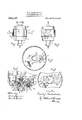
- Figure 1 is an elevation of my improved electrical drill.
- Fig. is
- Fig. 3 is a central longitudinal section of the chuck end of my improved drill. 1
- Fig 4 is a cross section on line wa of Fig. 3 wlth the armature shaft and its pinions removed.
- Fig. 5 is a cross section on line parts being attached to the middle part by screws, as shown, or otherwise.
- the middle part 2 1s provided with the o eratin said part 2.
- the switch for controlling the current is inclosed in the box 6, also attached to said part 2.
- the numeral 7 indicates an armature, of ordinary construction, having a shaft 8 carryin the pinions 9 and 10.
- the chuck end 11 as the bushing 12 extending into interior of the casin as shown in Fig. 3.
- the collar 23 Upon the upper end of the bushing 12 is the collar 23 thefunction of which is to prevent the displacement of the plate 13, and the frame 15 and to secure to said frame a free horizontal movement as well as to form a subjacent bearing for the spindle gear hereinafter described.
- the drill spindle 24; extending through the bushing 12 has keyed on its upper end the spurgear 25'.
- Similaily mounted on the pintle 17 is the double-gear 29, comprising the spur gear-30, adapted to intermesh with the pinion 9 on the armature shaft, and the pinion 31 adapted to intermesh'with the spur gear 25 on the drill spindle.
- the lower end of the armature shaft is journal'ed in the upper end of the drill spindle as shown and turns on the antifriction ball 32. 4
- the arm 33 Attached to the upper end of the pintle 16 is the arm 33 which extends through a slot 34 in the casing as shown in Fig. 2.
- the outer end of this arm is suitably shaped and serves as a catch for the hook 35 on the end of the switch lever 36.
- the spring 37 is adapted to throw'the switch lever to the ofi position as soon as the catch is released.
- the turnbutton 21 is adapted by turning to throw into mesh with the armature shaft and drill spindle gearing either of the double gears 26 or 29, by reason of the permanence of its radius from the common axis of said shaft and spindle, which is maintained by the plate 13, and because of the eccentric attachment of the frame 15 to the shank of said button, and the elliptical opening of said frame.
- the operating speed of the drill or other tool is thus changed merely by turning said button.
- the combination with a driving shaft and a driven shaft, of yieldablymounted intermediatepower transmission means for holding the axis of said yieldably mounted transmitter normally in a fixed relation to the axis of the member with which it engages and means for controlling the power supply actuated by the movement of said yieldably mounted transmitter around the axis of the member with which it engages.
- the combination with a driving shaft and a driven shaft, of yieldably mounted intermediate power transmission means for holding the axis of said yieldably-mounted transmitter normally in a fixed relation to the axis of the member with which it engages, and a switch for controlling the current actuated in disconnecting by the movement Qu lt-97 of said yieidably mounted transmitter around the axis of the member with which the combination with a driving sha t and a driven shaft, of a rock-frame, a plurality of back ears, said back gears being mounted with xed axes on said frame, and so the combination with a drivin cated that one at a time may be thrown into operative communication between said driving and drivenshafts, means for holding the axis of the o erativ back gear normally in a fixed re ation to the axis of the ear with which it intermeshes arid means for controlling the power su ply actuated by the movement of
- a device of the character s ecified the combination with a drivin sha t and a driven shaft, of a, movable rame, a plurality of double-back-gears, said back-gears being mounted with fixed axes on said frame, and being arranged for different s eeds, and so located that one at a time may e thrown into operative communication between said driving and driven shafts, a turnbutton, means for maintainin permanent radii between the axis of said utton and the axes of the gears with which said speed gears intermesh, said frame being eccentrically mounted on said button, so that by turning said button said speed-gears may bethrown, alternately in and out ofoperative communication between said driving and driven shafts, means for locking said frame into position when either of said speed-gears is in operation, a plurality of tension s rings equal in number to the speeds obtaina Is by means of said speedearsysaid s rin beingso
Landscapes
- Engineering & Computer Science (AREA)
- Power Engineering (AREA)
- Gear Transmission (AREA)
Description
F. J. BAGKSOHEIDER.
PORTABLE ELEGTRIGAL TOOL.
APPLICATION FILED FEB. 8, 1909.
Patented July 12,1910.
. omen STATES omen.
ram .1. nncxscnnmnn, or cmcrnn'mrfomo.
PORTABLE ELECTRICAL TOOL.
Specification of Iietters Intent.
964,197. Patented July 12, 1910. Application filed February 8, 1909. Serial No. 476,809.
To all whom it conccrnf another elevation showing the switch re- Be it known that I, FRANK J. BACK- sonnmmz, a citizen of the United States, residing in Cincinnati, in the county of Hamilton and State of Ohio, have invented a certain new and useful Im rovement in Portable Electrical Tools, 0 which the followin is a full, clear, and exact description, re erenoe being had to the accompanying drawings, forming part of this specification.
In portable electrical tools, especiallyin "such tools when used in drilling, it frequently hap ens that the drill or-other tool becomes stal ed in its work, and as a result the operating motor becomes overloaded, a short circuit is formed, and the armature is burned out. To prevent such overload falling on the motor, fuses are generally employed, and such fuses, by themselves being urned out, relieve the armature of any overload and consequent damage'upon' the stallin of the tool. The frequent annoyance 0 replacing a burned out fuse, however, results in a tendency to make use of a fuse which will not burn out readily, and the effect of this is to throw the overload on the motor burning out the armature when the tool becomes stalled. Electrical devices have frequently been used to prevent any overload damaging the armature by means of which when the current is increased to a point at which'an overload is imminent, resistance is automatically shunted into the circuit to revent damage to the armature. But such e ectrical devices are not found to operate with suflicient rapidity, and the short circuit is apt to occur before the current can be out down by hereinafter fully shown, and it is a further object of my invention to furnish a simple and expeditious means for throwing the gearing appropriate for the different speeds 1n and out of mesh as eithera high or low speed is required.
In the drawings Figure 1 is an elevation of my improved electrical drill. Fig. is
lease. Fig. 3 is a central longitudinal section of the chuck end of my improved drill. 1
Fig 4 is a cross section on line wa of Fig. 3 wlth the armature shaft and its pinions removed. Fig. 5 is a cross section on line parts being attached to the middle part by screws, as shown, or otherwise. The middle part 2 1s provided with the o eratin said part 2. The switch for controlling the current is inclosed in the box 6, also attached to said part 2. The numeral 7 indicates an armature, of ordinary construction, having a shaft 8 carryin the pinions 9 and 10. The chuck end 11 as the bushing 12 extending into interior of the casin as shown in Fig. 3. ,Fitting snugly around said bushing, and bearing on a retaining flange 42 of said bushing is the plate 13, said plate being provided with an arm extending over the slot 14: in the front wall of said casing. Also around said bushing, but fitting loosely, the opening bein in' the form of an ellipse as shown in ig. 5, is the movable frame 15, carrying the pintles 16 and 17 at its two ends. The end of said handles 55'which are immovab y attac ed to frame carrying the pintle 16 is shaped into 1 hereinafter set forth. Through the slot 14:"
in the casing, and through an opening near the end of the plate 13, adapted to fit it snugly, extends the shank of the turnbutton 21, to which the end of said frame 15 bearing the pintle 17 is eccentrically attached by means of the end 22 of said pintle which is turned down and extends through said button.
' Upon the upper end of the bushing 12 is the collar 23 thefunction of which is to prevent the displacement of the plate 13, and the frame 15 and to secure to said frame a free horizontal movement as well as to form a subjacent bearing for the spindle gear hereinafter described.
The drill spindle 24; extending through the bushing 12 has keyed on its upper end the spurgear 25'. Loosely mounted on the pintle 16 1s the double gear 26 comprising the spur gear 27 adapted to intermesh the pinion 10 on the armature shaft, and the pinion 28 adapted to intermesh with the spur gear 25 on the drill spindle. Similaily mounted on the pintle 17 is the double-gear 29, comprising the spur gear-30, adapted to intermesh with the pinion 9 on the armature shaft, and the pinion 31 adapted to intermesh'with the spur gear 25 on the drill spindle. The lower end of the armature shaft is journal'ed in the upper end of the drill spindle as shown and turns on the antifriction ball 32. 4
Attached to the upper end of the pintle 16 is the arm 33 which extends through a slot 34 in the casing as shown in Fig. 2. The outer end of this arm is suitably shaped and serves as a catch for the hook 35 on the end of the switch lever 36. The spring 37 is adapted to throw'the switch lever to the ofi position as soon as the catch is released.
The turnbutton 21 is adapted by turning to throw into mesh with the armature shaft and drill spindle gearing either of the double gears 26 or 29, by reason of the permanence of its radius from the common axis of said shaft and spindle, which is maintained by the plate 13, and because of the eccentric attachment of the frame 15 to the shank of said button, and the elliptical opening of said frame. The operating speed of the drill or other tool is thus changed merely by turning said button. To prevent the disengagement of either set of gearing, however, after it hasbeen thrown into mesh, I lock the frame 15 into either position by means of the pin 38 and the spring 39 about the reduced end 22 of the pintle 17 to which it is secured by a nut as shown in Fig. 3, which pin is adapted to engage openings 40 and 41 suitably located in the frame 15. By drawing the button slightly outward against the spring 39, the engagement of pin 38 is released and the button may then be turned to throw into mesh either set of gearing; upon being released the spring causes the pin to engage the appropriate opening thus locking the frame 15 and the required gear in the desired position.
The operation of my invention is as follows: When either set of gearing is thrown into mesh as above set forth, the head 18 of the frame 15 is brought to bear against one of the springs 19 or 20, as clearly shown in Figs. 4 and 5, and the other is opposite the notch in said head so as to offer no resistance against the movement of the frame 15 i against the bearing spring. Each of these springs is adjusted to the rated horse power of the tool at the operating speed effective when its correlated gearing is in mesh.
Assume now the parts to be in the position shown in the drawings Figs. 3, 4 and 5. So long as the drill or other tool works freely, the tension of the spring 19 holds the frame 15 and consequently the gearing in a fixed relationship with the common axis of the armature shaft and drill spindle. Should the tool become stalled, however, and the gear 25 thus cease-to revolve normally the resistance either will cause the field to rotate in the opposite direction, which the operators grasp of the handles will prevent it from doing, or the pinion 28, mounted on the frame 15, will be compelled to turn aroundthe said gear 25 with a planetary motion which the mounting of said frame, the slot 14 in the casing, and the overload on the sprin 19 will permit it to do. This movement of the frame, however, carr ing with. it the arm 33, releases the catch rom engagement with the book 35 and the switch lever 36 is immediately thrown to the ofl' position by the spring 37, thus disconnecting the current and relieving the armature of any overload. Precisely the same result follows the stalling of the tool when the opposite set of gearing is in mesh and the s' ring 20 is opposed to the movement 0 the frame 15.
Having thus described my invention what I claim as new and desire to secure by Letters Patent, is:
1. In a device of the character specified, the combination with a driving shaft and a driver shaft, of yieldably mounted intermediate power transmission, and means for controlling the power supply actuated by the movement of said yieldably mounted transmitter around the axis of the member with which it enga es.
2. In a devlce of the character specified, the combination with a driving shaft and a driven shaft, of yieldablymounted intermediatepower transmission, means for holding the axis of said yieldably mounted transmitter normally in a fixed relation to the axis of the member with which it engages and means for controlling the power supply actuated by the movement of said yieldably mounted transmitter around the axis of the member with which it engages.
3. In a device of the character speclfied, the combination with a driving shaft and a driven shaft, of yieldably mounted intermediate power transmission, and a switch for controlling the current actuated in disconnecting by the movement of said yieldably mounted transmitter around the axis ofthe member with which it engages.
4. In a device of the character specified, the combination with a driving shaft and a driven shaft, of yieldably mounted intermediate power transmission, means for holding the axis of said yieldably-mounted transmitter normally in a fixed relation to the axis of the member with which it engages, and a switch for controlling the current actuated in disconnecting by the movement Qu lt-97 of said yieidably mounted transmitter around the axis of the member with which the combination with a driving sha t and a driven shaft, of a rock-frame, a plurality of back ears, said back gears being mounted with xed axes on said frame, and so the combination with a drivin cated that one at a time may be thrown into operative communication between said driving and drivenshafts, means for holding the axis of the o erativ back gear normally in a fixed re ation to the axis of the ear with which it intermeshes arid means for controlling the power su ply actuated by the movement of t e axis 0 the operative back gear around the axis of the gear with which it intermeshes.
6. Ina device of the character specified, the combination with a drivin driven shaft, of a movable rame, a plurality of back gears said back gears being mounted with fixed axes on said frame, and so located that one at a time may be thrown into operative communication between said driving and driven shafts and a switch for controlling the current actuated in disconnecting by the movement of the operative back gear around the axis of the gear with which it intermeshes.
7.- In a device of the character :s ecified,
driven shaft, of a movable rame, a plurality of back gears, said back gears bein mounted with fixed axeson said frame, an so located that one at a time. may be thrown into operative communication between said driving and driven shafts, means for holdingthe axis of the operative back gear normally in a fixed relation to the axis of the ear with which it intermeshes, and a switch for controlling the current actuated in dis connecting by the movement of the operative back gear around the axis of the gear with which it intermeshes.
8. In a device of the character specified, the combination with the driving shaft and a driven shaft, of a rock-frame, a plurality of double back gears, said back gears being mounted with fixed axes on said frame, and being arranged for different speeds, and so located that one at a time may be thrown into operative communication between said driving and driven shafts, means for throwing said speed gears in and out of operative communication gbetween said driving and driven shafts, means for bold ing the axis of the operative back gear normally in a fixed relation to the axis of the gear with which it intermeshes and means or controlling the power supply actuated by the movement of the axisof the operative back gear around the axis of the gear with which it intermeshes.
9, In a device of the character specified,
rality of double-back gears,
the movement shaft and asha t and a' the combinatioii'with adrivin shaft and a driven shaft, of a movable ame, a plub said back gears mounted with fixed axes on said frame,
and in arranged fordiiferents eeds, and
so locate that one at a time may thrown 1nt o -operative communication between said drlving and driven shafts, means for throw: mg said speed-gears in and out of operative communlcation between said drivmg and dr1 ven shafts, and aswitch for controlling the current actuated in disconnecting by of the axis of the operative back-gear around the axis of the gear with which it intermeshes.
10. In a device of the character specified, the combination with a driving shaft and a driven shaft, of a movable frame, a plurality of double-back-gears, said back-gears being; mounted with fixed axes on said frame, and eing arrangedfor different s eeds, and so located that one at a time may be thrown into operative communication between said driving and driven shafts, means for throwing said speed-gears in and out of operative communication between said driving and driven shafts, means for holding the axis of the operative back-gear normally in a fixed relation to the axis of the gear with which it intermeshes, and a switch for controlling the current actuated in disconnecting by the movement of the operative back-gear around the axis of the gear with which it interme'shes.
11. In a device of the character specified, the combination'with'a driving shaft and a driven shaft, of a movable frame, a plurality of speed gears mounted on said frame, a turn utton with center at a fixed distance from the axes of the gear with which said speed gears intermesh, said frame being eccentrically-mounted on said button, so that by turning said button said speed gears may be thrown-alternately in and out of operative communication between said driving and driven shafts, means for locking said frame into position when either ofsaid speed gears is in mesh and means for-controlling the power supply actuated by the movement of the axis of the operative speed gear around the axis of the. gear with which it intormeshes.
12. In a device of the character specified, the combination with a driving shaft and a driven shaft, of a movable frame, a plurality of double-back gears, said back-gears bein mounted with fixed axes on said frame, an being arranged for different speeds, and so located that one at a time ma be thrown into operative communication etween said driving and driven shafts, a turnbutton, means for maintainin permanent radii between the axis of said button and the axes of the gears with which said speed gears intermesh, said frame being eceentrically mounted on'said button, so that by turning said button said s eed gears may be thrown alternately in an munication between said driving and dr ven shafts, means for locking said frame into position when either of said speed-gears 19 in operation, means for holdm the axis of the operative back-gear norma y in afixed relation to the axis of the gear with which it intermeshes and means for controlling the power sup ly actuated by the movement of the axis 0 the operative back gear around the axis of the gear with which it intermeshes.
13. In a device of the character specified, the combination with a driving shaft and a driven shaft, of a movable frame, a plurality of double-back-gears, said back-gears being mounted with fixed axes on said frame, and being arranged for different speeds, and so located that one at a time may be thrown into operative communication between said driving and driven shafts, a turnbutton, means for maintaining ermanent radnbetween the axis of said utton and the axes of the gears with which said speed gears intermesh, said frame bein eccentrically mounted on said button, so t at by turning said button said speed-gears may be thrown alternately in and out of operative communication between said driving and driven shafts, means for locking said frame into position when either of said speed-gears is in operation, means for holding the axis of the operative back-gear normally in a fixed relation to the axis of the gear with wh ch it intermeshes, and a switch for controlling the current actuated in disconnecting by the movement of the operative back-gear around the axis of the gear with which it intermeshes.
14. In a device of the character specified, the combination with a driving shaft and a driven shaft, of amovable frame, a plurality of double-back-gears, said back-gears being mounted with fixed axe's on said frame, and being arranged for different speeds, and so located that one at a time may be thrown into operative communication between said driving and driven shafts, a turnbutton, means for maintaining permanent radii between the axis of said button and the axes of the gears with which said speed gears intermesh, said frame being eccentrically mounted on said button, so that by turning said button said speed-gears may be thrown alternately in and out of operative communication between said driving and driven shafts, means for locking said frame into position when either of said speed-gears is in operation, a plurality of tension-springs equal in number to the speeds obtainable by means of said speed-gears, said springs being so arranged as to bear each individually on said frame when a correlated speedout of operative com-v gear is in operation, and being each adjusted to therated horse-power when said correlated gear is in o eration, to hold the axis of the operative ack-gear normally in a fixed relation to the axis of the gear with which it intermeshes and means for controlling the power supply actuated by the movement of the axis of the operative back gear around the axis of the gear with which t intermeshes.
15. In a device of the character s ecified,.
the combination with a drivin sha and a driven shaft, of a movable rame, a plurality of double-back-gears, said back-gears bein mounted with fixed axes on said frame, and eing arranged for different speeds, and so located that one at a time may be thrown into operative communication between said driving and driven shafts, a turnbutton, means for maintaining permanent radii between the axis of said button and the axes of the gears with which said speed-gears intermesh, said frame being eccentrically mounted on said button, so that by turning said button said speed-gears may be thrown alternately in and out of operative communication between said driving and driven shafts, means for locking said frame into position when either of said speed-gears is in operation, a plurality of tension s rings equal in number to the speeds obtainable by means of said speedears, said springs being so arranged as to ear each individually on said frame when a correlated speed-gear is in operation, and being each adjusted to the rated horse-power when said correlated gear is in operation, to hold the axis of the operative back-gear normally in a fixed relation to the axis of the gear with which it intermeshes, and a switch for controlling the current actuated in disconnecting by the movement of the operative back-gear around the axis of the gear with which it intermeshes.
16. In a device of the character s ecified, the combination with a drivin sha t and a driven shaft, of a, movable rame, a plurality of double-back-gears, said back-gears being mounted with fixed axes on said frame, and being arranged for different s eeds, and so located that one at a time may e thrown into operative communication between said driving and driven shafts, a turnbutton, means for maintainin permanent radii between the axis of said utton and the axes of the gears with which said speed gears intermesh, said frame being eccentrically mounted on said button, so that by turning said button said speed-gears may bethrown, alternately in and out ofoperative communication between said driving and driven shafts, means for locking said frame into position when either of said speed-gears is in operation, a plurality of tension s rings equal in number to the speeds obtaina Is by means of said speedearsysaid s rin beingso arranged as to ear each in 'vi ually on said frame when a'correlated speedear is in operation, and being each adjuste to the rated horse-power when said correlated gearis in operation, to hold the axis of the operative back gear normally in a fixed relation to the axis of the gear with which it intermeshes, and a switch for controlling the run in Letters Patent No. 964,197.
[snarh] Correct current, with a catch on said frame for lock- 10 ing the switch, whereby upon the movement of said frame against the pressure of said tension spring the switch will be operated.
' FRANK J. BAOKSCHEDER.
-Wit1sses: A B
nssm EALL, EARL W. GRIFFIN.
It is hereby certified that in Letters Patent No. 964,197, granted July 12, 1910, upon the application of rank J. Backscheider, of Cincinnati, Ohio,'for an improvement in Portable Electrical Tools, an error appears in the printed specification requiring correction, as follows: Page 2, line 97, the word driver should read driven; and that the said Letters Patent should be read with this correction "therein, that the same may conform to the record of the case in the Patent Office.
Signed and sealed this 9th day of August, A. D., 1910.
F. A. TENNANT,
Acting Commissioner of Patents.
Priority Applications (1)
| Application Number | Priority Date | Filing Date | Title |
|---|---|---|---|
| US47680909A US964197A (en) | 1909-02-08 | 1909-02-08 | Portable electrical tool. |
Applications Claiming Priority (1)
| Application Number | Priority Date | Filing Date | Title |
|---|---|---|---|
| US47680909A US964197A (en) | 1909-02-08 | 1909-02-08 | Portable electrical tool. |
Publications (1)
| Publication Number | Publication Date |
|---|---|
| US964197A true US964197A (en) | 1910-07-12 |
Family
ID=3032594
Family Applications (1)
| Application Number | Title | Priority Date | Filing Date |
|---|---|---|---|
| US47680909A Expired - Lifetime US964197A (en) | 1909-02-08 | 1909-02-08 | Portable electrical tool. |
Country Status (1)
| Country | Link |
|---|---|
| US (1) | US964197A (en) |
Cited By (2)
| Publication number | Priority date | Publication date | Assignee | Title |
|---|---|---|---|---|
| US2499928A (en) * | 1947-06-03 | 1950-03-07 | Franklin Appliance Company | Food mixer electric motor assembly |
| US4066133A (en) * | 1974-09-04 | 1978-01-03 | Robert Bosch G.M.B.H. | Power hand tool |
-
1909
- 1909-02-08 US US47680909A patent/US964197A/en not_active Expired - Lifetime
Cited By (2)
| Publication number | Priority date | Publication date | Assignee | Title |
|---|---|---|---|---|
| US2499928A (en) * | 1947-06-03 | 1950-03-07 | Franklin Appliance Company | Food mixer electric motor assembly |
| US4066133A (en) * | 1974-09-04 | 1978-01-03 | Robert Bosch G.M.B.H. | Power hand tool |
Similar Documents
| Publication | Publication Date | Title |
|---|---|---|
| US2086030A (en) | Driving mechanism for valves | |
| DE102011004126A1 (en) | Hand tool with a reduction gear | |
| US2029094A (en) | Power transmission mechanism | |
| US1218236A (en) | Power-driven tool. | |
| US801012A (en) | Disconnecting mechanism. | |
| US2683848A (en) | Overload control for motors | |
| US3908492A (en) | Variable speed motor driven machine tool | |
| US3144783A (en) | Tapping attachment | |
| US3220313A (en) | Machine tool power drawbolt mechanism | |
| US2667076A (en) | Energy storing overrunning operating device | |
| US2775904A (en) | Portable tool | |
| US1967045A (en) | Chuck and press actuating mechanism | |
| US741686A (en) | Speed-changing device. | |
| US2846034A (en) | Combined gear reduction and clutch mechanism | |
| US1213354A (en) | Power transmission. | |
| US1229570A (en) | Automatic power cut-off. | |
| US3109319A (en) | Back gear control for lathe drive | |
| US3308684A (en) | Gear type transmission | |
| US2885899A (en) | Preselective speed changer | |
| US1481245A (en) | Safety hand feed | |
| US2129653A (en) | Engine starter | |
| US971307A (en) | Safety limit-switch. | |
| US1380021A (en) | Raising and lowering means in metal-working machinery | |
| US2379428A (en) | Engine starter | |
| US3005527A (en) | Positive drive tapping attachments |