US9638124B2 - Control device for engine - Google Patents
Control device for engine Download PDFInfo
- Publication number
- US9638124B2 US9638124B2 US14/859,044 US201514859044A US9638124B2 US 9638124 B2 US9638124 B2 US 9638124B2 US 201514859044 A US201514859044 A US 201514859044A US 9638124 B2 US9638124 B2 US 9638124B2
- Authority
- US
- United States
- Prior art keywords
- accelerator opening
- target acceleration
- predetermined range
- range
- pedal
- Prior art date
- Legal status (The legal status is an assumption and is not a legal conclusion. Google has not performed a legal analysis and makes no representation as to the accuracy of the status listed.)
- Expired - Fee Related, expires
Links
Images


Classifications
-
- F—MECHANICAL ENGINEERING; LIGHTING; HEATING; WEAPONS; BLASTING
- F02—COMBUSTION ENGINES; HOT-GAS OR COMBUSTION-PRODUCT ENGINE PLANTS
- F02D—CONTROLLING COMBUSTION ENGINES
- F02D41/00—Electrical control of supply of combustible mixture or its constituents
- F02D41/02—Circuit arrangements for generating control signals
- F02D41/04—Introducing corrections for particular operating conditions
- F02D41/10—Introducing corrections for particular operating conditions for acceleration
-
- B—PERFORMING OPERATIONS; TRANSPORTING
- B60—VEHICLES IN GENERAL
- B60K—ARRANGEMENT OR MOUNTING OF PROPULSION UNITS OR OF TRANSMISSIONS IN VEHICLES; ARRANGEMENT OR MOUNTING OF PLURAL DIVERSE PRIME-MOVERS IN VEHICLES; AUXILIARY DRIVES FOR VEHICLES; INSTRUMENTATION OR DASHBOARDS FOR VEHICLES; ARRANGEMENTS IN CONNECTION WITH COOLING, AIR INTAKE, GAS EXHAUST OR FUEL SUPPLY OF PROPULSION UNITS IN VEHICLES
- B60K26/00—Arrangement or mounting of propulsion-unit control devices in vehicles
- B60K26/02—Arrangement or mounting of propulsion-unit control devices in vehicles of initiating means or elements
- B60K26/021—Arrangement or mounting of propulsion-unit control devices in vehicles of initiating means or elements with means for providing feel, e.g. by changing pedal force characteristics
-
- F—MECHANICAL ENGINEERING; LIGHTING; HEATING; WEAPONS; BLASTING
- F02—COMBUSTION ENGINES; HOT-GAS OR COMBUSTION-PRODUCT ENGINE PLANTS
- F02D—CONTROLLING COMBUSTION ENGINES
- F02D11/00—Arrangements for, or adaptations to, non-automatic engine control initiation means, e.g. operator initiated
- F02D11/06—Arrangements for, or adaptations to, non-automatic engine control initiation means, e.g. operator initiated characterised by non-mechanical control linkages, e.g. fluid control linkages or by control linkages with power drive or assistance
- F02D11/10—Arrangements for, or adaptations to, non-automatic engine control initiation means, e.g. operator initiated characterised by non-mechanical control linkages, e.g. fluid control linkages or by control linkages with power drive or assistance of the electric type
- F02D11/105—Arrangements for, or adaptations to, non-automatic engine control initiation means, e.g. operator initiated characterised by non-mechanical control linkages, e.g. fluid control linkages or by control linkages with power drive or assistance of the electric type characterised by the function converting demand to actuation, e.g. a map indicating relations between an accelerator pedal position and throttle valve opening or target engine torque
-
- F—MECHANICAL ENGINEERING; LIGHTING; HEATING; WEAPONS; BLASTING
- F02—COMBUSTION ENGINES; HOT-GAS OR COMBUSTION-PRODUCT ENGINE PLANTS
- F02D—CONTROLLING COMBUSTION ENGINES
- F02D11/00—Arrangements for, or adaptations to, non-automatic engine control initiation means, e.g. operator initiated
- F02D11/06—Arrangements for, or adaptations to, non-automatic engine control initiation means, e.g. operator initiated characterised by non-mechanical control linkages, e.g. fluid control linkages or by control linkages with power drive or assistance
- F02D11/10—Arrangements for, or adaptations to, non-automatic engine control initiation means, e.g. operator initiated characterised by non-mechanical control linkages, e.g. fluid control linkages or by control linkages with power drive or assistance of the electric type
- F02D11/106—Detection of demand or actuation
-
- B—PERFORMING OPERATIONS; TRANSPORTING
- B60—VEHICLES IN GENERAL
- B60K—ARRANGEMENT OR MOUNTING OF PROPULSION UNITS OR OF TRANSMISSIONS IN VEHICLES; ARRANGEMENT OR MOUNTING OF PLURAL DIVERSE PRIME-MOVERS IN VEHICLES; AUXILIARY DRIVES FOR VEHICLES; INSTRUMENTATION OR DASHBOARDS FOR VEHICLES; ARRANGEMENTS IN CONNECTION WITH COOLING, AIR INTAKE, GAS EXHAUST OR FUEL SUPPLY OF PROPULSION UNITS IN VEHICLES
- B60K26/00—Arrangement or mounting of propulsion-unit control devices in vehicles
- B60K26/02—Arrangement or mounting of propulsion-unit control devices in vehicles of initiating means or elements
- B60K26/021—Arrangement or mounting of propulsion-unit control devices in vehicles of initiating means or elements with means for providing feel, e.g. by changing pedal force characteristics
- B60K2026/023—Arrangement or mounting of propulsion-unit control devices in vehicles of initiating means or elements with means for providing feel, e.g. by changing pedal force characteristics with electrical means to generate counter force or torque
-
- F—MECHANICAL ENGINEERING; LIGHTING; HEATING; WEAPONS; BLASTING
- F02—COMBUSTION ENGINES; HOT-GAS OR COMBUSTION-PRODUCT ENGINE PLANTS
- F02D—CONTROLLING COMBUSTION ENGINES
- F02D2200/00—Input parameters for engine control
- F02D2200/50—Input parameters for engine control said parameters being related to the vehicle or its components
- F02D2200/501—Vehicle speed
-
- F—MECHANICAL ENGINEERING; LIGHTING; HEATING; WEAPONS; BLASTING
- F02—COMBUSTION ENGINES; HOT-GAS OR COMBUSTION-PRODUCT ENGINE PLANTS
- F02D—CONTROLLING COMBUSTION ENGINES
- F02D2250/00—Engine control related to specific problems or objectives
- F02D2250/18—Control of the engine output torque
-
- F—MECHANICAL ENGINEERING; LIGHTING; HEATING; WEAPONS; BLASTING
- F02—COMBUSTION ENGINES; HOT-GAS OR COMBUSTION-PRODUCT ENGINE PLANTS
- F02D—CONTROLLING COMBUSTION ENGINES
- F02D41/00—Electrical control of supply of combustible mixture or its constituents
- F02D41/02—Circuit arrangements for generating control signals
- F02D41/021—Introducing corrections for particular conditions exterior to the engine
- F02D41/0215—Introducing corrections for particular conditions exterior to the engine in relation with elements of the transmission
- F02D41/0225—Introducing corrections for particular conditions exterior to the engine in relation with elements of the transmission in relation with the gear ratio or shift lever position
-
- F—MECHANICAL ENGINEERING; LIGHTING; HEATING; WEAPONS; BLASTING
- F02—COMBUSTION ENGINES; HOT-GAS OR COMBUSTION-PRODUCT ENGINE PLANTS
- F02D—CONTROLLING COMBUSTION ENGINES
- F02D41/00—Electrical control of supply of combustible mixture or its constituents
- F02D41/24—Electrical control of supply of combustible mixture or its constituents characterised by the use of digital means
- F02D41/2406—Electrical control of supply of combustible mixture or its constituents characterised by the use of digital means using essentially read only memories
- F02D41/2409—Addressing techniques specially adapted therefor
- F02D41/2422—Selective use of one or more tables
Definitions
- the present invention relates to a control device for an engine, particularly to a control device for an engine, which adjusts an engine torque according to an operation of an accelerator pedal performed by a driver.
- JP2005-155412A discloses such a kind of art.
- a target torque of an engine is set based on a state of accelerator operation performed by a driver, and an output torque of the engine is adjusted to reach the target torque by adjusting a throttle opening and/or an ignition timing.
- an output torque of an engine is adjusted such that an acceleration of a vehicle in its longitudinal direction becomes higher as a depressing speed of an accelerator pedal (i.e., a differential value of an accelerator opening) becomes higher, so as to gain an acceleration feeling and reduce vibration of the vehicle in its longitudinal direction.
- the present invention is made in view of the above situations and aims to provide a control device for an engine, which can suitably maintain a constant vehicle speed when accelerator operation is performed in a state where a driver applies almost no intentional force with his/her foot.
- a control system for an engine adjusts an engine torque based on an operation of an organ-type accelerator pedal for pivoting about a supporting point.
- the control system includes an accelerator opening acquiring module for acquiring an accelerator opening that is a position of the accelerator pedal, a target acceleration setting module for setting a target acceleration of a vehicle based on the accelerator opening acquired by the accelerator opening acquiring module, and an engine control module for adjusting the engine torque to achieve the target acceleration set by the target acceleration setting module.
- the target acceleration setting module sets the target acceleration corresponding to the accelerator opening acquired by the accelerator opening acquiring module, by using a predetermined range of the accelerator opening including a value at which the target acceleration becomes zero.
- the predetermined range is set such that a pedal reaction force F (N) applied from a predetermined position of the accelerator pedal when the accelerator opening is within the predetermined range is within a range of “2.5(N) ⁇ F ⁇ 26(N),” the predetermined position being 172 (mm) away from the supporting point of the accelerator pedal.
- the accelerator opening in such a case is within the predetermined range (the range of the accelerator opening including the value at which the target acceleration becomes zero). Therefore, when traveling on a rotary, a roundabout, or a limited speed zone where the vehicle speed is limited to be low, etc., even if the driver operates the accelerator pedal slightly and repeatedly so as to keep the vehicle speed constant, the target acceleration set according to the accelerator opening corresponding to such accelerator operation tends to become close to zero. Thus, the variation of the vehicle speed can suitably be suppressed.
- the driver can easily maintain the constant vehicle speed, in other words, can easily control the vehicle to maintain the constant vehicle speed, when the driver operates the accelerator pedal while applying almost no intentional force with his/her foot.
- the predetermined range is preferably set such that the pedal reaction force F(N) applied when the accelerator opening is within the predetermined range is within a range expressed by the following Equation 1 defined with a vehicle speed V (km/h). F ⁇ 0.0321 V+ 19.7 (1)
- the predetermined range is set such that the pedal reaction force F(N) applied when the accelerator opening is within the predetermined range is within the range expressed by Equation 1 defined with the vehicle speed V (km/h).
- the predetermined range is set by defining a largest value of the range of the pedal reaction force F (N) based on the vehicle speed V (km/h).
- the predetermined range can suitably be set according to the vehicle speed, and by using such a predetermined range, the constant vehicle speed can more easily be maintained.
- the predetermined range is preferably set such that the pedal reaction force F (N) applied when the accelerator opening is within the predetermined range is within a range expressed by the following Equation 2 defined with the vehicle speed V (km/h). F ⁇ 0.017 V+ 2.57 (2)
- the predetermined range is set such that the pedal reaction force F (N) applied when the accelerator opening is within the predetermined range is within the range expressed by Equation 2 defined with the vehicle speed V (km/h).
- the predetermined range is set by defining a smallest value of the range of the pedal reaction force F (N) based on the vehicle speed V (km/h).
- the predetermined range can suitably be set according to the vehicle speed, and by using such a predetermined range, the constant vehicle speed can more easily be maintained.
- the predetermined range is preferably set such that the pedal reaction force F (N) applied when the accelerator opening is within the predetermined range is within a range of “2.5(N) ⁇ F ⁇ 23(N).”
- the predetermined range is set by using the range of the pedal reaction force F (N) that is obtained based on a vehicle speed range which is frequently used in normal operation, such that the pedal reaction force F (N) applied when the accelerator opening is within the predetermined range is within the range of “2.5(N) ⁇ F ⁇ 23(N).”
- the vehicle speed within the frequently-used vehicle speed range can more easily be kept constant.
- the target acceleration setting module preferably causes a change of the target acceleration with respect to a change of the accelerator opening to be smaller than when the accelerator opening is above the predetermined range and larger than when the accelerator opening is below the predetermined range.
- the change of the target acceleration with respect to the change of the accelerator opening is adjusted to be larger. Therefore, the vehicle can swiftly be accelerated according to an increase of the accelerator opening. In other words, the driver can gain a satisfactory acceleration feeling.
- the change of the target acceleration with respect to the change of the accelerator opening is adjusted to be smaller. Therefore, variation of the acceleration according to the variation of the accelerator opening within a small value range, for example, the variation of the accelerator opening caused by the “play” of the accelerator pedal, can suitably be suppressed.
- the target acceleration setting module preferably causes a change of the target acceleration with respect to a change of the accelerator opening to be substantially constant regardless of a gear position of the vehicle.
- the target acceleration corresponding to the accelerator opening is set such that the change of the target acceleration with respect to the change of the accelerator opening is substantially constant regardless of the gear position of a transmission of the vehicle.
- the change of the acceleration with respect to the change of the accelerator opening can be substantially the same among various gear positions. Therefore, the constant vehicle speed can easily be maintained regardless of the gear position.
- the target acceleration setting module preferably causes a change of the target acceleration with respect to a change of the accelerator opening to be substantially constant regardless of a vehicle speed.
- the target acceleration corresponding to the accelerator opening is set such that the change of the target acceleration with respect to the change of the accelerator opening is substantially constant regardless of the vehicle speed.
- the change of the acceleration with respect to the change of the accelerator opening can be substantially the same among various vehicle speeds. Therefore, the constant vehicle speed can easily be maintained regardless of the vehicle speed.
- a method of controlling a control system for an engine adjusts an engine torque based on operation of an organ-type accelerator pedal for pivoting about a supporting point.
- the method includes acquiring an accelerator opening that is a position of the accelerator pedal, setting a target acceleration of a vehicle based on the acquired accelerator opening, and adjusting the engine torque to achieve the set target acceleration.
- the setting of the target acceleration includes setting the target acceleration corresponding to the acquired accelerator opening, by using a predetermined range of the accelerator opening including a value at which the target acceleration becomes zero.
- the predetermined range is set such that a pedal reaction force F (N) applied from a predetermined position of the accelerator pedal when the accelerator opening is within the predetermined range is within a range of “2.5(N) ⁇ F ⁇ 26(N),” the predetermined position being 172 (mm) away from the supporting point of the accelerator pedal.
- the target acceleration corresponding to the acquired accelerator opening is set by using the predetermined range of the accelerator opening including the value of the accelerator opening at which the target acceleration becomes zero. Moreover, such a predetermined range of the accelerator opening is set such that the pedal reaction force F (N) applied from the predetermined position being 172 (mm) away from the supporting point (pivot point) of the accelerator pedal is within the range of “2.5(N) ⁇ F ⁇ 26(N)” when the accelerator opening is within the predetermined range.
- the accelerator opening for such a case is within the predetermined range (the range of the accelerator opening including the value at which the target acceleration becomes zero). Therefore, when traveling on a rotary, a roundabout, or a limited speed zone where the vehicle speed is limited to be low, etc., even if the driver operates the accelerator pedal slightly and repeatedly so as to keep the vehicle speed constant, the target acceleration set according to the accelerator opening corresponding to such accelerator operation tends to become close to zero. Thus, variation of the vehicle speed can suitably be suppressed.
- the driver can easily maintain the constant vehicle speed, in other words, can easily control the vehicle to maintain the constant vehicle speed, when the driver operates the accelerator pedal while applying almost no intentional force with his/her foot.
- FIG. 1 is a plan view illustrating a schematic configuration of a vehicle to which a control device for an engine according to one embodiment of the present invention is applied.
- FIG. 2 is a view illustrating a schematic configuration of an engine system to which the control device for the engine according to the embodiment of the present invention is applied.
- FIG. 3 is a side view of an accelerator pedal according to the embodiment of the present invention.
- FIG. 4 is a pedal characteristic chart illustrating one example of a relationship between an accelerator opening and a pedal reaction force according to the embodiment of the present invention.
- FIG. 5 is a block diagram illustrating a functional configuration of an engine control unit (ECU) according to the embodiment of the present invention.
- ECU engine control unit
- FIG. 6 is a chart illustrating one example of an acceleration characteristic map according to the embodiment of the present invention.
- FIG. 7A to 7C show time charts illustrating changes of an accelerator opening, a target acceleration, and a vehicle speed, respectively, when a first acceleration characteristic map segment according to the embodiment of the present invention is applied.
- FIGS. 8A to 8C show examples of the acceleration characteristic map for different gear positions and vehicle speeds, respectively, according to the embodiment of the present invention.
- FIG. 9 is a chart illustrating a basic concept of a method of determining a first range according to the embodiment of the present invention.
- FIG. 10 is a view for describing a definition of the pedal reaction force according to the embodiment of the present invention, and illustrating a schematic side view of the accelerator pedal.
- FIG. 11 is a chart illustrating a relationship between the accelerator opening and the pedal reaction force measured at a predetermined position of a pedal part illustrated in FIG. 10 , obtained in the embodiment of the present invention.
- FIG. 12 is a table including specific values of an upper threshold and a lower threshold of a hysteresis for respective vehicle speeds, obtained in the embodiment of the present invention.
- FIG. 13 is a chart illustrating a relationship of the vehicle speed with the upper and lower thresholds of the hysteresis, obtained in the embodiment of the present invention.
- FIG. 14 is a flowchart illustrating an engine control according to the embodiment of the present invention.
- FIG. 1 is a plan view illustrating a schematic configuration of a vehicle to which the control device for the engine according to this embodiment of the present invention is applied.
- FIG. 2 is a view illustrating a schematic configuration of the engine system to which the control device for the engine according to this embodiment of the present invention is applied.
- the engine 10 of the engine system 100 produces an engine torque (drive torque) as a thrust of the vehicle by causing combustion of mixture gas containing fuel and air, and transfers the engine torque to a transmission 202 via a crankshaft 16 .
- the transmission 202 changes a gear position among a plurality of positions (e.g., first to sixth ranges), and at a gear position set by the transmission 202 , the engine torque from the engine 10 is transferred, via a pair of drive shafts 204 , to a pair of wheels 206 attached to outer end parts of the drive shafts 204 in vehicle width directions, respectively.
- an ECU 50 performs various controls within the vehicle.
- the ECU 50 functions as the control device of the engine.
- the ECU 50 adjusts the engine torque which is outputted by the engine 10 , and supplies the engine torque to the vehicle.
- the ECU 50 improves a desirable acceleration characteristic in relation to the accelerator operation.
- the engine system 100 includes an intake passage 1 through which intake air (air) introduced from outside passes, the engine (specifically, gasoline engine) 10 for producing a drive force of the vehicle by causing combustion of the mixture gas containing the intake air supplied from the intake passage 1 and the fuel supplied from a fuel injector 13 (described later), an exhaust passage 25 for discharging exhaust gas produced by the combustion within the engine 10 , sensors 30 to 39 for detecting various states regarding the engine system 100 , and the ECU 50 for controlling the engine system 100 entirely.
- the engine specifically, gasoline engine
- the engine 10 for producing a drive force of the vehicle by causing combustion of the mixture gas containing the intake air supplied from the intake passage 1 and the fuel supplied from a fuel injector 13 (described later)
- an exhaust passage 25 for discharging exhaust gas produced by the combustion within the engine 10
- sensors 30 to 39 for detecting various states regarding the engine system 100
- the ECU 50 for controlling the engine system 100 entirely.
- the intake passage 1 is provided with, from its upstream side in the following order, an air cleaner 3 for purifying the intake air introduced from outside, a throttle valve 5 for adjusting an amount of intake air passing therethrough (intake air amount), and a surge tank 7 for temporarily storing the intake air to be supplied to the engine 10 .
- the engine 10 mainly includes an intake valve 12 for introducing, into a combustion chamber 11 , the intake air supplied from the intake passage 1 , the fuel injector 13 for injecting the fuel to the combustion chamber 11 , an ignition plug 14 for igniting the mixture gas (containing the intake air and the fuel) supplied into the combustion chamber 11 , a piston 15 for reciprocating due to the combustion of the mixture gas within the combustion chamber 11 , the crankshaft 16 which is rotated by the reciprocation of the piston 15 , and an exhaust valve 17 for discharging, to the exhaust passage 25 , the exhaust gas produced by the combustion of the mixture gas within the combustion chamber 11 .
- the engine 10 varies operation timings of the intake and exhaust valves 12 and 17 (corresponding to phases of the valves) by a variable intake valve mechanism 18 and a variable exhaust valve mechanism 19 (both being a variable valve timing mechanism), respectively.
- a variable intake valve mechanism 18 and a variable exhaust valve mechanism 19 both being a variable valve timing mechanism
- Various known types thereof may be applied for the variable intake valve mechanism 18 and the variable exhaust valve mechanism 19 , and for example, an electromagnetic-operated type mechanism or a hydraulic type mechanism may be used to change the operation timings of the intake valve 12 and the exhaust valve 17 .
- the exhaust passage 25 is mainly provided with exhaust gas purifying catalysts 26 a and 26 b having a function of purifying the exhaust gas, such as an NOx catalyst, a three-way catalyst, or an oxidation catalyst.
- exhaust gas purifying catalysts 26 a and 26 b may each simply be described as the “exhaust gas purifying catalyst 26 .”
- the engine system 100 is provided with the sensors 30 to 39 for detecting the various states regarding the engine system 100 .
- the sensors 30 to 39 are specifically as follows: the accelerator opening sensor 30 for detecting a position of the accelerator pedal 29 (corresponding to an amount by which the driver depresses the accelerator pedal 29 ); the airflow sensor 31 for detecting the intake air amount corresponding to the flow rate of the intake air passing through the intake passage 1 ; the throttle opening sensor 32 for detecting an opening of the throttle valve 5 (throttle opening); the pressure sensor 33 for detecting an intake manifold pressure corresponding to the pressure of the intake air which is supplied to the engine 10 ; the crank angle sensor 34 for detecting a crank angle of the crankshaft 16 ; the water temperature sensor 35 for detecting a temperature of cooling water for cooling the engine 10 (water temperature); the temperature sensor 36 for detecting a temperature inside a cylinder of the engine 10 (in-cylinder temperature); the cam angle sensors 37 and 38 for detecting the operation timings (including close timings) of the intake and exhaust valves 12 and 17 , respectively
- the ECU 50 controls the components of the engine system 100 based on the detection signals S 30 to S 39 received from the various sensors 30 to 39 described above. Specifically, the ECU 50 supplies a control signal S 5 to the throttle valve 5 to adjust open and close timings of the throttle valve 5 and the throttle opening, supplies a control signal S 13 to the fuel injector 13 to adjust a fuel injection amount and a fuel injection timing, supplies a control signal S 14 to the ignition plug 14 to adjust an ignition timing, and supplies control signals S 18 and S 19 to the variable intake valve mechanism 18 and the variable exhaust valve mechanism 19 to adjust the operation timings of the intake and exhaust valves 12 and 17 , respectively.
- FIG. 3 is a side view of the accelerator pedal 29 according to the embodiment of the present invention.
- the accelerator pedal 29 is configured as an organ-type pedal, and includes a pedal part 29 a pivotably attached to a base part 29 b.
- the pedal part 29 a is pivotably supported at its lower end by the base part 29 b so as to stand therefrom, and pivots by a predetermined angle (e.g.,)15.1° from an initial position corresponding to a no-load state (the illustrated state) to a terminal position on a vehicle forward side, due to being depressed by the driver.
- a housing 29 c integrally formed with the base part 29 b is provided below the pedal part 29 a.
- a restoring spring (not illustrated), a so-called return spring, is provided inside the housing 29 c, and a plurality of links 29 d (three links in total to be specific, although only one of them is illustrated in FIG. 3 ) are provided between an internal structure body of the housing 29 c and the pedal part 29 a.
- Such a restoring spring and the plurality of links 29 d configure a pedal reaction force producing mechanism 29 e.
- the pedal reaction force producing mechanism 29 e produces a reaction force in proportion to a pivot amount of the pedal part 29 a (see the pedal reaction force within a normal operation range in FIG. 4 ).
- the housing 29 c is provided with the accelerator opening sensor 30 described above.
- the accelerator opening sensor 30 produces the detection signal S 30 corresponding to the accelerator opening according to the pivoted position (angle) of the pedal part 29 a.
- a kick down switch 29 f is provided at an upper surface part of the housing 29 c facing a lower surface of the pedal part 29 a.
- the kick down switch 29 f produces a predetermined peak reaction force (see the pedal reaction force within a kick down stroke range in FIG. 4 ) larger than that produced by the pedal reaction force producing mechanism 29 e, to act against the pivot of the pedal part 29 a to the terminal position.
- the accelerator opening sensor 30 detects this operation and produces the detection signal S 30 corresponding to a kick down signal, so as to automatically shift down the transmission 202 (to a lower gear position).
- the engine torque and the vehicle speed are increased.
- FIG. 4 is a pedal characteristic chart illustrating one example of a relationship between the accelerator opening and the pedal reaction force caused by the accelerator pedal 29 according to the embodiment of the present invention.
- the horizontal axis indicates the accelerator opening and the vertical axis indicates the pedal reaction force.
- the pedal reaction force is a force which is applied to the sole of the foot of the driver by the accelerator pedal 29 , in other words, it corresponds to a depressing force which is applied to the accelerator pedal 29 by the foot (same hereinafter).
- the pedal reaction force is measured by a pressure sensor provided at a predetermined position of the accelerator pedal 29 .
- a range R 11 of the accelerator opening is the normal operation range where only the pedal reaction force is applied by the pedal reaction force producing mechanism 29 e of the accelerator pedal 29
- a range R 12 where the accelerator opening is larger than the range R 11 is the kick down stroke range where the pedal reaction force caused by the kick down switch 29 f of the accelerator pedal 29 is applied in addition to the pedal reaction force caused by pedal reaction force producing mechanism 29 e.
- a graph G 11 indicates a relationship between the accelerator opening and the pedal reaction force caused by the pedal reaction force producing mechanism 29 e, which is applied when the accelerator pedal 29 is depressed (see the arrow A 11 ).
- a graph G 12 indicates a relationship between the accelerator opening and the pedal reaction force caused by the pedal reaction force producing mechanism 29 e, which is applied when the accelerator pedal 29 is released (see the arrow A 12 ).
- a hysteresis indicated by the reference numeral R 13 is provided between the graph G 11 and the graph G 12 .
- the characteristic of the accelerator pedal 29 indicated by the graph G 11 may be set such that the pedal reaction force becomes larger than the weight of the foot (the weight of an ankle itself) so as to require the driver to operate the accelerator pedal 29 by applying an intentional force with his/her foot.
- the characteristic of the accelerator pedal 29 indicated by the graph G 12 may be set such that the pedal reaction force becomes smaller than the weight of the foot (the weight of the ankle itself) so as to allow the driver to operate the accelerator pedal 29 with almost no intentional force with his/her foot. In this manner, when the driver releases the accelerator pedal 29 to keep it at a predetermined accelerator opening, almost no intentional force of the foot is required from the driver.
- the ECU 50 of this embodiment functionally has an accelerator opening acquiring module 50 a, a target acceleration setting module 50 b, and an engine control module 50 c.
- the accelerator opening acquiring module 50 a acquires the accelerator opening (e.g., expressed in “%”) based on the detection signal S 30 outputted by the accelerator opening sensor 30 .
- the target acceleration setting module 50 b sets a target acceleration of the vehicle based on the accelerator opening acquired by the accelerator opening acquiring module 50 a . Specifically, the target acceleration setting module 50 b sets the target acceleration corresponding to the accelerator opening acquired by the accelerator opening acquiring module 50 a, by referring to a map in which the target acceleration to be set in relation to the accelerator opening is defined before use (acceleration characteristic map).
- the engine control module 50 c adjusts the engine torque to achieve the target acceleration set by the target acceleration setting module 50 b. Specifically, the engine control module 50 c sets a target torque required for shifting an actual acceleration to the target acceleration, and controls the throttle valve 5 and/or the intake valve 12 through the variable intake valve mechanism 18 , and additionally controls the fuel injector 13 , etc., so as to cause the engine 10 to output the target torque.
- the ECU 50 may be referred to as “the control device for the engine.”
- an acceleration characteristic applied in this embodiment is described.
- an acceleration characteristic map of this embodiment in which a characteristic of the target acceleration to be set in relation to the accelerator opening is defined, is described in detail.
- the acceleration characteristic map is used for the target acceleration setting module 50 b of the ECU 50 to set the target acceleration.
- FIG. 6 is a chart illustrating one example of the acceleration characteristic map according to the embodiment of the present invention.
- the horizontal axis indicates the accelerator opening
- the vertical axis indicates the target acceleration.
- the upper side of “0” indicates values of the target acceleration which cause the vehicle to accelerate
- the lower side of zero indicates values of the target acceleration which cause the vehicle to decelerate (target deceleration).
- the “0” at the origin of the chart does not mean that the acceleration is zero, but means that the accelerator opening is zero.
- the acceleration characteristic map in FIG. 6 is a single map applied for a certain gear position and a certain vehicle speed.
- the accelerator opening is defined to have three ranges (first to third ranges R 21 , R 22 , and R 23 ). Further in this embodiment, three acceleration characteristic map segments (first to third acceleration characteristic map segments M 1 , M 2 and M 3 ) are defined as maps which are applied to the first to third ranges R 21 , R 22 , and R 23 , respectively. In this embodiment, the first to third acceleration characteristic map segments constitute the above-described single map applied for a certain gear position and a certain vehicle speed.
- the first range R 21 of the accelerator opening includes a value of the accelerator opening at which the target acceleration becomes zero (see the point P 1 ).
- a first range R 21 is defined based on a range of the accelerator opening to which the accelerator pedal 29 is set when the accelerator pedal 29 is operated in a state where the driver applies almost no intentional force with his/her foot (i.e., a state of depressing the accelerator pedal 29 with the weight of the foot itself).
- a range of about ⁇ 5% centering on the value of the accelerator opening corresponding to the point P 1 is applied as the first range R 21
- the second range R 22 of the accelerator opening is a range where the accelerator opening is larger than the first range R 21
- the third range R 23 of the accelerator opening is a range including the accelerator opening “0” and where the accelerator opening is smaller than the first range R 21 .
- the first range R 21 including the value of the accelerator opening at which the target acceleration becomes zero is, in other words, a range including a value of the accelerator opening at which traveling resistance (including air resistance, road surface resistance and resistance received from a road depending on its inclination) balances with the drive force which is applied to the wheels.
- the value of the accelerator opening at which the target acceleration becomes zero corresponds to the value of the accelerator opening at which such traveling resistance balances with the drive force which is applied to the wheels.
- the first acceleration characteristic map segment M 1 applied to the first range R 21 described above is defined to have a smaller (more gradual) inclination indicating the change of the target acceleration with respect to the change of the accelerator opening, compared to the second acceleration characteristic map segment M 2 applied to the second range R 22 .
- the change of the acceleration corresponding to the change of the accelerator opening within the first range R 21 is smaller than that within the second range R 22 to which the second acceleration characteristic map segment M 2 is applied.
- the second acceleration characteristic map segment M 2 is defined to have a larger (steeper) inclination indicating the change of the target acceleration with respect to the change of the accelerator opening, compared to the first acceleration characteristic map segment M 1 .
- the vehicle smoothly accelerates according to an increase of the accelerator opening within the second range R 22 .
- the first acceleration characteristic map segment M 1 is defined to have a larger (steeper) inclination indicating the change of the target acceleration with respect to the change of the accelerator opening, compared to the third acceleration characteristic map segment M 3 applied to the third range R 23 .
- the third acceleration characteristic map segment M 3 is defined to have a smaller (more gradual) inclination indicating the change of the target acceleration with respect to the change of the accelerator opening, compared to the first acceleration characteristic map segment M 1 . According to such a third acceleration characteristic map segment M 3 , the acceleration is adjusted so as not to change greatly according to the variation of the accelerator opening within a range near zero (corresponding to the “play”, free travel, of the accelerator pedal 29 ).
- the target acceleration setting module 50 b of the ECU 50 selects one of the first to third acceleration characteristic map segments M 1 to M 3 according to a range under which the accelerator opening acquired by the accelerator opening acquiring module 50 a falls among the first to third ranges R 21 to R 23 , and, by using the selected map segment, the target acceleration setting module 50 b sets the target acceleration corresponding to the accelerator opening acquired by the accelerator opening acquiring module 50 a.
- FIGS. 7A to 7C show time charts illustrating changes of the accelerator opening, the target acceleration, and the vehicle speed, respectively, in the case where the first acceleration characteristic map segment M 1 of this embodiment is applied when the accelerator opening is within the first range R 21 .
- FIG. 7A illustrates the change of the accelerator opening over time
- FIG. 7B illustrates the change of the target acceleration over time
- FIG. 7C illustrates the change of the vehicle speed over time.
- the accelerator is operated by the driver to keep the vehicle speed constant (typically to keep the vehicle speed low)
- the driver tends to operate the accelerator pedal 29 slightly and repeatedly (see FIG. 7A ). Since such slight and repeated operation of the accelerator pedal 29 for keeping the vehicle speed constant is performed within the first range R 21 of the accelerator opening including the point P 1 (see FIG. 6 ), the first acceleration characteristic map segment M 1 is selected, and the target acceleration is set by using the first acceleration characteristic map segment M 1 . Therefore, the target acceleration which varies within a small range near zero is set (see FIG. 7B ). As a result, the vehicle speed is suitably kept substantially constant (see FIG. 7C ).
- the first to third acceleration characteristic map segments M 1 to M 3 illustrated in FIG. 6 are applied for a certain gear position and a certain vehicle speed.
- the acceleration characteristic map segments (the acceleration characteristic map as a whole) are basically defined for each gear position (i.e., the gear position set by the transmission 202 , corresponding to an engine load) and each vehicle speed.
- the acceleration characteristic map is defined according to the gear position and the vehicle speed.
- FIGS. 8A to 8C show examples of the acceleration characteristic map for different gear positions and vehicle speeds, respectively, according to this embodiment of the present invention.
- the horizontal axis indicates the accelerator opening and the vertical axis indicates the target acceleration.
- FIG. 8A illustrates the acceleration characteristic map applied at the vehicle speed of 30 km/h
- FIG. 8B illustrates the acceleration characteristic map applied at the vehicle speed of 60 km/h
- FIG. 8C illustrates the acceleration characteristic map applied at the vehicle speed of 90 km/h
- the graphs G 21 to G 25 in FIG. 8A indicate the acceleration characteristic maps applied for five gear positions, respectively.
- the graphs G 31 to G 35 in FIG. 8B indicate the acceleration characteristic maps applied for the five gear positions, respectively.
- the graphs G 41 to G 45 in FIG. 8C indicate the acceleration characteristic maps applied for the five gear positions, respectively.
- acceleration characteristic maps applied for the vehicle speeds 30 km/h, 60 km/h, and 90 km/h are illustrated as examples, but in actuality, acceleration characteristic maps applied for various other vehicle speeds (which may include 30 km/h, 60 km/h, and 90 km/h) are prepared. Further, the vehicle to which the engine system 100 of this embodiment is applied actually has the six gear positions; however, since a first gear position is exceptional, an acceleration characteristic map applied for the first gear position is not illustrated in FIGS. 8A to 8C .
- the acceleration characteristic map segment M 1 applied within the first range R 21 described above is defined such that the change of the target acceleration with respect to the change of the accelerator opening becomes substantially constant regardless of the gear position and the vehicle speed.
- the acceleration characteristic map segment M 1 is defined such that the inclination indicating the change of the target acceleration with respect to the change of the accelerator opening becomes substantially constant regardless of the gear position and the vehicle speed.
- the change of the acceleration with respect to the change of the accelerator opening is substantially the same among various gear positions and vehicle speeds.
- the second and third acceleration characteristic map segments M 2 and M 3 applied within the second and third ranges R 22 and R 23 are defined such that the change of the target acceleration with respect to the change of the accelerator opening is different, in other words, the inclination indicating the change of the target acceleration with respect to the change of the accelerator opening is different, according to the gear position and the vehicle speed.
- the acceleration suitably changes according to a current gear position and a current vehicle speed.
- FIG. 9 is a chart illustrating one example of a relationship between the accelerator opening and the pedal reaction force (pedal characteristic) similar to FIG. 4 .
- the horizontal axis indicates the accelerator opening and the vertical axis indicates the pedal reaction force, and elements which are the same as those in FIG. 4 (including elements which are not completely the same but are similar and have the same concept) are denoted with the same reference numerals and/or characters as FIG. 4 .
- the graph G 13 indicated by the dashed line is a force applied to the accelerator pedal 29 by the weight of the foot itself (the weight of a part from the ankle to the tip of the foot) of the driver.
- a weight of a small foot e.g., a woman's foot
- a weight of a small foot is illustrated as an example.
- the force applied by the weight of the foot itself becomes slightly larger as the accelerator opening becomes larger because of an inclination of the accelerator pedal 29 (an inclination of the pedal part 29 a with respect to the base part 29 b ) becomes smaller and the application of the force of the foot (force applied mainly by the weight) is easily affected by the accelerator pedal 29 (a component of force applied to the accelerator pedal 29 with the foot becomes larger), in other words, the influence of the weight (force of gravitation) of the foot on the accelerator pedal 29 becomes larger.
- the driver can operate the accelerator pedal 29 by applying almost no intentional force with his/her foot. Specifically in this case, the driver can operate the accelerator pedal 29 to keep a current accelerator opening by applying almost no intentional force with his/her foot.
- At least part of the range A 3 of the accelerator opening where the force applied by the weight of the foot itself (graph G 13 ) is in the hysteresis R 13 is set as the first range R 21 described above.
- the accelerator opening at this timing is included in the first range R 21 .
- the first acceleration characteristic map segment M 1 is selected to set the target acceleration. Therefore in this case, the vehicle speed can suitably be kept substantially constant (see FIG. 7C ).
- the definition of “the accelerator pedal is operated in the state where the driver applies almost no intentional force with his/her foot” corresponds to accelerator operation in which the accelerator pedal 29 is naturally depressed only by the movement of the ankle without the driver intentionally depressing the accelerator pedal 29 with his/her entire leg.
- This accelerator operation is performed by mainly using the weight of the part from the ankle to the tip of the foot (weight of that part itself).
- the first range R 21 of this embodiment is described in detail with reference to FIGS. 10 to 13 . Specifically, a range of the pedal reaction force used for defining the width of the first range R 21 is described in detail.
- FIG. 10 is a view for describing a definition of the pedal reaction force according to the embodiment of the present invention, and illustrating a schematic side view of the accelerator pedal 29 .
- the width of the first range 21 is defined by using a pedal reaction force applied to a position P 22 which is on the pedal part 29 a and 172 (mm) away from a supporting point P 21 (pivot point) when the pedal part 29 a of the accelerator pedal 29 pivots.
- a pressure sensor is provided at the position P 22 and the pressure measured by the pressure sensor is used as the pedal reaction force.
- the position P 22 which is 172 (mm) away from the supporting point P 21 corresponds to a position of the pedal part 29 a with which the ball of a large foot (e.g., a man's foot) contacts.
- FIG. 11 is a chart illustrating a relationship between the accelerator opening and the pedal reaction force measured at the position P 22 on the pedal part 29 a described above.
- the horizontal axis indicates the accelerator opening (%) and the vertical axis indicates the pedal reaction force (N), and elements which are the same as those in FIGS. 4 and 9 (including elements which are not completely the same but are similar and have the same concept) are denoted with the same reference numerals and/or characters as FIGS. 4 and 9 .
- the graph G 14 indicates the force applied to the accelerator pedal 29 by the weight of the large (man's) foot (the part from the ankle to the tip) itself.
- the force applied by the weight of the large (man's) foot itself is larger than that by the weight of the small ( woman's) foot itself.
- 25% is acquired as the value of the accelerator opening at which the target acceleration becomes zero from the first acceleration characteristic map segment M 1 for 80 (km/h)
- 32% is acquired as the value of the accelerator opening at which the target acceleration becomes zero from the first acceleration characteristic map segment M 1 for 120 (km/h)
- 45% is acquired as the value of the accelerator opening at which the target acceleration becomes zero from the first acceleration characteristic map segment M 1 for 200 (km/h).
- the first acceleration characteristic map segments M 1 for the respective vehicle speeds are not illustrated.
- an upper threshold P 31 and a lower threshold P 41 of the pedal reaction force (N) defining the range of the hysteresis R 13 are acquired at the accelerator opening of 25% for 80 (km/h) (hereinafter, the pedal reaction force defining the upper threshold of the hysteresis may simply be referred to as the “up-HYS threshold,” and the pedal reaction force defining the lower threshold of the hysteresis may simply be referred to as the “low-HYS threshold”).
- an up-HYS threshold P 32 and a low-HYS threshold P 42 are acquired at the accelerator opening of 32% for 120 (km/h) and an up-HYS threshold P 33 and a low-HYS threshold P 43 are acquired at the accelerator opening of 45% for 200 (km/h).
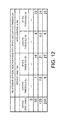
- FIG. 12 is a table including specific values of the up-HYS thresholds P 31 , P 32 , and P 33 and the low-HYS thresholds P 41 , P 42 , and P 43 for 80 (km/h), 120 (km/h), and 200 (km/h) described above.
- the low-HYS threshold P 41 and the up-HYS threshold P 31 for 80 (km/h) are 7 (N) and 19 (N)
- the low-HYS threshold P 42 and the up-HYS threshold P 32 for 120 (km/h) are 7.5 (N) and 21 (N)
- the low-HYS threshold P 43 and the up-HYS threshold P 33 for 200 (km/h) are 9 (N) and 23 (N).
- FIG. 12 also includes the up-HYS thresholds and the low-HYS thresholds taking a variation of the pedal reaction force into consideration.
- the variation is ⁇ 3 (N).
- the low-HYS threshold with the variation becomes 4 (N) by subtracting 3 (N) from 7 (N) which is the low-HYS threshold P 41
- the up-HYS threshold with the variation becomes 22 (N) by adding 3 (N) to 19 (N) which is the up-HYS threshold P 31 .
- FIG. 13 is a chart illustrating a relationship of the vehicle speed with the up-HYS threshold and the low-HYS threshold based on the up-HYS thresholds and the low-HYS thresholds obtained for the respective vehicle speeds in FIG. 12 (using the thresholds with the variation).
- the horizontal axis indicates the vehicle speed (km/h) and the vertical axis indicates the pedal reaction force (N).
- points P 51 and P 61 indicate the up-HYS threshold and the low-HYS threshold with the variation at 80 (km/h)
- points P 52 and P 62 indicate the up-HYS threshold and the low-HYS threshold with the variation at 120 (km/h)
- points P 53 and P 63 indicate the up-HYS threshold and the low-HYS threshold with the variation at 200 (km/h).
- An approximate line indicated by the graph G 51 can be obtained based on the up-HYS thresholds P 51 , P 52 , and P 53 at 80 (km/h), 120 (km/h) and 200 (km/h).
- the approximate line indicated by the graph G 51 can be expressed by the following Equation 3.
- an approximate line indicated by the graph G 52 can be obtained based on the low-HYS thresholds P 61 , P 62 and P 63 at 80 (km/h), 120 (km/h) and 200 (km/h), and the approximate line indicated by the graph G 52 can be expressed by the following Equation 4.
- F 0.0321 V+ 19.714 (3)
- F 0.017 V+ 2.5714 (4)
- the first range R 21 is set based on such a range of the pedal reaction force F (N). Specifically, the first range R 21 is set such that the pedal reaction force F (N) applied to the position P 22 , which is 172 mm away from the supporting point P 21 on the pedal part 29 a of the accelerator pedal 29 , is within the range of “2.5(N) ⁇ F ⁇ 26(N)” when the accelerator opening is within the first range R 21 .
- the first range R 21 may be set such that the pedal reaction force F (N) applied to the position P 22 on the pedal part 29 a when the accelerator opening is within the first range R 21 is within a range expressed by the following Equation 5 that is established based on Equation 3 described above. Equation 5 is obtained by defining the largest value of the pedal reaction force F (N) corresponding to the vehicle speed V (km/h). F ⁇ 0.0321 V+ 19.7 (5)
- the first range R 21 may be set such that the pedal reaction force F (N) applied to the position P 22 on the pedal part 29 a when the accelerator opening is within the first range R 21 is within a range expressed by the following Equation 6 established based on Equation 4 described above. Equation 6 is obtained by defining the smallest value of the pedal reaction force F (N) corresponding to the vehicle speed V (km/h). F ⁇ 0.017 V+ 2.57 (6)
- the first range R 21 may be set such that the range of the pedal reaction force F (N) applied to the position P 22 on the pedal part 29 a when the accelerator opening is within the first range R 21 is “2.5(N) ⁇ F ⁇ 23(N).”
- the largest value “23 (N)” defining the range is obtained by substituting “100 (km/h)” in Equation 3.
- the range of the pedal reaction force F (N) defined by using “23 (N)” is obtained based on a vehicle speed range (0 to 100 km/h) which is frequently used in normal operations.
- the various ranges of the pedal reaction force F (N) described above are defined by representatively using the position P 22 which is 172 mm away from the supporting point P 21 on the pedal part 29 a of the accelerator pedal 29 . Therefore, on the pedal part 29 a other than the position P 22 (i.e., positions of the pedal part 29 a where the distance from the supporting point P 21 is not 172 mm), the range of the pedal reaction force F (N) is obviously different from the example described above.
- the range of the pedal reaction force F (N) when defining at a position of the pedal part 29 a where the distance from the supporting point P 21 is larger than 172 mm, the range of the pedal reaction force F (N) is shifted lower, and when defining at a position of the pedal part 29 a where the distance from the supporting point P 21 is smaller than 172 mm, the range of the pedal reaction force F (N) is shifted higher.
- the value of the pedal reaction force F (N) is in inverse proportion to the distance from the supporting point P 21 . Therefore, the range of the pedal reaction force F (N) shifts by an amount corresponding to such a relationship.
- the range of the pedal reaction force F (N) defined at the position P 22 which is on the pedal part 29 a and 172 mm away from the supporting point P 21 is given merely as an example, and the width of the various ranges of the pedal reaction force F (N) shifted according to the position on the pedal part 29 a (i.e., according to the distance from the supporting point P 21 ) is substantially the same as the range of the pedal reaction force F (N) raised in the embodiment.
- FIG. 14 is a flowchart illustrating the engine control according to the embodiment of the present invention. This flow is repeated at a predetermined time cycle by the ECU 50 of the engine system 100 .
- the ECU 50 acquires an operating state of the vehicle. Specifically, the ECU 50 acquires, as the operating state of the vehicle, the accelerator opening detected by the accelerator opening sensor 30 (specifically, the accelerator opening acquired by the accelerator opening acquiring module 50 a of the ECU 50 based on the detection signal S 30 outputted by the accelerator opening sensor 30 ), the vehicle speed detected by the vehicle speed sensor 39 , the gear position currently set at the transmission 202 , etc.
- the accelerator opening detected by the accelerator opening sensor 30 specifically, the accelerator opening acquired by the accelerator opening acquiring module 50 a of the ECU 50 based on the detection signal S 30 outputted by the accelerator opening sensor 30
- the vehicle speed detected by the vehicle speed sensor 39 the gear position currently set at the transmission 202 , etc.
- the target acceleration setting module 50 b of the ECU 50 sets the target acceleration based on the accelerator opening, the vehicle speed, and the gear position acquired at S 1 . Specifically, the target acceleration setting module 50 b first selects an acceleration characteristic map corresponding to the current vehicle speed and the current gear position, from the acceleration characteristic maps defined for various vehicle speeds and gear positions (the acceleration characteristic maps are created and stored in a memory or the like before use).
- the target acceleration setting module 50 b further selects one of the first to third acceleration characteristic map segments M 1 to M 3 of the acceleration characteristic map selected based on the vehicle speed and the gear position, and the target acceleration setting module 50 b sets the target acceleration corresponding to the current accelerator opening by referring the selected map segment.
- the engine control module 50 c of the ECU 50 sets the target torque of the engine 10 so as to achieve the target acceleration set at S 2 .
- the engine control module 50 c sets the target torque based on the current vehicle speed, etc., because when the vehicle speed increases, the traveling resistance becomes high, and therefore, the target torque needs to be set large.
- the engine control module 50 c sets the target torque within a range that the engine 10 can output.
- the engine control module 50 c controls the engine 10 to output the target torque set at S 3 .
- the engine control module 50 c adjusts the opening of the throttle valve 5 and/or the operation timing of the intake valve 12 through the variable intake valve mechanism 18 (intake VVT control) by taking into consideration the intake air amount detected by the airflow sensor 31 , so that the air amount corresponding to the target torque is introduced into the engine 10 .
- the engine control module 50 c also controls the fuel injector 13 to inject the fuel injection amount determined based on the theoretical air-fuel ratio thereof with the air amount which corresponds to the target torque.
- the first range R 21 including the value of the accelerator opening at which the target acceleration becomes zero is set such that the pedal reaction force F (N) applied to the position which is 172 mm away from the supporting point P 21 of the pedal part 29 a of the accelerator pedal 29 , is within the range of “2.5(N) ⁇ F ⁇ 26(N)” when the accelerator opening is within the first range R 21 (see FIG. 13 ), and the target acceleration corresponding to the current accelerator opening is set according to the first acceleration characteristic map segment M 1 defined for such a first range R 21 , so as to control the engine torque.
- the accelerator opening for such a case is within the first range R 21 and the first acceleration characteristic map segment M 1 in which the inclination indicating the change of the target acceleration with respect to the change of the accelerator opening is more gradual is applied. Therefore, when traveling on a rotary, a roundabout, or a limited speed zone where the vehicle speed is limited to be low, etc., even if the driver operates the accelerator pedal 29 slightly and repeatedly so as to keep the vehicle speed constant, the variation of the target acceleration which is set according to the accelerator opening corresponding to the accelerator operation becomes small.
- the vehicle speed can suitably be kept substantially constant.
- the driver can easily maintain the constant vehicle speed, in other words, can easily control the vehicle to maintain the constant vehicle speed, when the driver operates the accelerator pedal 29 while applying almost no intentional force with his/her foot.
- the first range R 21 is set such that the pedal reaction force F (N) applied when the accelerator opening is within the first range R 21 is within the range expressed by Equation 5 and/or Equation 6 defined with the vehicle speed.
- the first range R 21 is set based on the range (the largest value and/or the smallest value) of the pedal reaction force F (N) corresponding to the vehicle speed.
- the first range R 21 can be set suitably for the vehicle speed, and by using such a first range R 21 , the constant vehicle speed can more easily be maintained.
- the first range R 21 is set such that the range of the pedal reaction force F (N) applied when the accelerator opening is within the first range R 21 becomes “2.5(N) ⁇ F ⁇ 23(N).” Since the range of the pedal reaction force F (N) is obtained based on the vehicle speed range (0 to 100 km/h) which is frequently used in normal operations, by using the first range R 21 corresponding to the range of the pedal reaction force F (N), the vehicle speed within the frequently-used vehicle speed range can more easily be kept constant.
- the second acceleration characteristic map segment M 2 in which the inclination indicating the change of the target acceleration with respect to the change of the accelerator opening is steep is applied within the second range R 22 where the accelerator opening is larger than the first range R 21 (see FIG. 6 ). Therefore, the vehicle can swiftly be accelerated according to the increase of the accelerator opening within the second range R 22 . In other words, the driver can gain a satisfactory acceleration feeling.
- the first acceleration characteristic map segment M 1 applied within the first range R 21 including the value of the accelerator opening at which the target acceleration becomes zero is defined such that the change of the target acceleration with respect to the change of the accelerator opening becomes substantially constant regardless of the gear position and the vehicle speed ( FIGS. 8A to 8C ).
- the change of the acceleration with respect to the change of the accelerator opening can be substantially the same among various gear positions and vehicle speeds. Therefore, according to the embodiment, the constant vehicle speed can easily be maintained regardless of the gear position and the vehicle speed.
- the present invention is not limited to be applied to the gasoline engine, and may similarly be applied to a diesel engine.
- the first acceleration characteristic map segment M 1 is defined such that the change of the target acceleration with respect to the change of the accelerator opening becomes substantially constant regardless of both of the gear position and the vehicle speed ( FIGS. 8A to 8C ).
- the first acceleration characteristic map segment M 1 may be defined such that the change of the target acceleration with respect to the change of the accelerator opening is substantially constant regardless of the vehicle speed, while the change of the target acceleration with respect to the change of the accelerator opening is different according to the gear position.
- the first acceleration characteristic map segment M 1 may be defined such that the change of the target acceleration with respect to the change of the accelerator opening is substantially constant regardless of the gear position, while the change of the target acceleration with respect to the change of the accelerator opening is different according to the vehicle speed.
Landscapes
- Engineering & Computer Science (AREA)
- Chemical & Material Sciences (AREA)
- Combustion & Propulsion (AREA)
- Mechanical Engineering (AREA)
- General Engineering & Computer Science (AREA)
- Transportation (AREA)
- Control Of Throttle Valves Provided In The Intake System Or In The Exhaust System (AREA)
- Auxiliary Drives, Propulsion Controls, And Safety Devices (AREA)
Abstract
Description
F≦0.0321V+19.7 (1)
F≧0.017V+2.57 (2)
F=0.0321V+19.714 (3)
F=0.017V+2.5714 (4)
F≦0.0321V+19.7 (5)
F≧0.017V+2.57 (6)
Claims (19)
F≧0.017V+2.57 (2).
F≦0.0321V+19.7 (1).
F≧0.017V+2.57 (2).
Applications Claiming Priority (2)
| Application Number | Priority Date | Filing Date | Title |
|---|---|---|---|
| JP2015-056339 | 2015-03-19 | ||
| JP2015056339A JP6260794B2 (en) | 2015-03-19 | 2015-03-19 | Engine control device |
Publications (2)
| Publication Number | Publication Date |
|---|---|
| US20160273469A1 US20160273469A1 (en) | 2016-09-22 |
| US9638124B2 true US9638124B2 (en) | 2017-05-02 |
Family
ID=56924534
Family Applications (1)
| Application Number | Title | Priority Date | Filing Date |
|---|---|---|---|
| US14/859,044 Expired - Fee Related US9638124B2 (en) | 2015-03-19 | 2015-09-18 | Control device for engine |
Country Status (2)
| Country | Link |
|---|---|
| US (1) | US9638124B2 (en) |
| JP (1) | JP6260794B2 (en) |
Families Citing this family (8)
| Publication number | Priority date | Publication date | Assignee | Title |
|---|---|---|---|---|
| JP6226146B2 (en) * | 2015-03-03 | 2017-11-08 | マツダ株式会社 | Engine control device |
| JP6249180B2 (en) * | 2015-05-22 | 2017-12-20 | マツダ株式会社 | Engine control device |
| JP6098844B2 (en) * | 2015-05-22 | 2017-03-22 | マツダ株式会社 | Engine control device |
| JP6098843B2 (en) * | 2015-05-22 | 2017-03-22 | マツダ株式会社 | Engine control device |
| JP7251461B2 (en) * | 2019-12-13 | 2023-04-04 | トヨタ自動車株式会社 | control system |
| JP7694106B2 (en) | 2021-03-30 | 2025-06-18 | マツダ株式会社 | Vehicle Control Systems |
| JP7694105B2 (en) | 2021-03-30 | 2025-06-18 | マツダ株式会社 | Vehicle Control Systems |
| FR3163317B1 (en) * | 2024-06-17 | 2026-05-01 | Stellantis Auto Sas | METHOD FOR IMPROVING THE DRIVING EXPERIENCE OF A MOTOR VEHICLE WHEN THE ACCELERATOR PEDAL IS ACTIVATED |
Citations (9)
| Publication number | Priority date | Publication date | Assignee | Title |
|---|---|---|---|---|
| JPH04345541A (en) | 1991-05-21 | 1992-12-01 | Hitachi Ltd | Control device for automobile |
| JP2005155412A (en) | 2003-11-25 | 2005-06-16 | Toyota Motor Corp | Output torque control device for internal combustion engine |
| US20050177308A1 (en) * | 2004-02-06 | 2005-08-11 | Nissan Motor Co., Ltd. | Lane deviation avoidance system |
| JP2006117020A (en) | 2004-10-19 | 2006-05-11 | Toyota Motor Corp | Vehicle travel control device |
| JP2006123603A (en) | 2004-10-26 | 2006-05-18 | Toyota Motor Corp | Vehicle control device |
| JP2010264831A (en) | 2009-05-13 | 2010-11-25 | Honda Motor Co Ltd | Vehicle fuel consumption rate improvement support device |
| US20120221220A1 (en) | 2011-02-23 | 2012-08-30 | Mikuni Corporation | Accelerator pedal apparatus |
| JP2014088137A (en) | 2012-10-31 | 2014-05-15 | Denso Corp | Accelerator |
| US20140379213A1 (en) * | 2012-02-07 | 2014-12-25 | Toyota Jidosha Kabushiki Kaisha | Drive assisting device |
-
2015
- 2015-03-19 JP JP2015056339A patent/JP6260794B2/en not_active Expired - Fee Related
- 2015-09-18 US US14/859,044 patent/US9638124B2/en not_active Expired - Fee Related
Patent Citations (9)
| Publication number | Priority date | Publication date | Assignee | Title |
|---|---|---|---|---|
| JPH04345541A (en) | 1991-05-21 | 1992-12-01 | Hitachi Ltd | Control device for automobile |
| JP2005155412A (en) | 2003-11-25 | 2005-06-16 | Toyota Motor Corp | Output torque control device for internal combustion engine |
| US20050177308A1 (en) * | 2004-02-06 | 2005-08-11 | Nissan Motor Co., Ltd. | Lane deviation avoidance system |
| JP2006117020A (en) | 2004-10-19 | 2006-05-11 | Toyota Motor Corp | Vehicle travel control device |
| JP2006123603A (en) | 2004-10-26 | 2006-05-18 | Toyota Motor Corp | Vehicle control device |
| JP2010264831A (en) | 2009-05-13 | 2010-11-25 | Honda Motor Co Ltd | Vehicle fuel consumption rate improvement support device |
| US20120221220A1 (en) | 2011-02-23 | 2012-08-30 | Mikuni Corporation | Accelerator pedal apparatus |
| US20140379213A1 (en) * | 2012-02-07 | 2014-12-25 | Toyota Jidosha Kabushiki Kaisha | Drive assisting device |
| JP2014088137A (en) | 2012-10-31 | 2014-05-15 | Denso Corp | Accelerator |
Also Published As
| Publication number | Publication date |
|---|---|
| JP2016176388A (en) | 2016-10-06 |
| JP6260794B2 (en) | 2018-01-17 |
| US20160273469A1 (en) | 2016-09-22 |
Similar Documents
| Publication | Publication Date | Title |
|---|---|---|
| US9638124B2 (en) | Control device for engine | |
| US9581091B2 (en) | Control device for engine | |
| US9944180B2 (en) | Control device for engine | |
| US6619258B2 (en) | System for controllably disabling cylinders in an internal combustion engine | |
| US8352146B2 (en) | Engine response adjustment based on traffic conditions | |
| US6334424B1 (en) | Control device and control method for vehicle | |
| US9964060B2 (en) | Control device for engine | |
| JP2015017570A (en) | Vehicle control device | |
| US9765704B2 (en) | Control device for engine | |
| EP1774159B1 (en) | Device and method for controlling an internal combustion engine | |
| US8630785B2 (en) | Fuel management systems and methods for variable displacement engines | |
| US9964059B2 (en) | Control device for engine | |
| US10465614B2 (en) | Vehicle control device | |
| US10220838B2 (en) | Vehicle control device | |
| US9222422B2 (en) | Output characteristic control device for internal combustion engine | |
| JP6196042B2 (en) | Power unit controller | |
| JP7694106B2 (en) | Vehicle Control Systems | |
| US20040134701A1 (en) | Constant speed running control apparatus for vehicle and method thereof | |
| JP2009047129A (en) | Vehicle motion control device | |
| JPH10238618A (en) | Transmission | |
| JP6709028B2 (en) | Variable capacity compressor controller | |
| CN115075909A (en) | Exhaust sound tuning system and method | |
| JP2020122412A (en) | Vehicular control apparatus | |
| JP2019044883A (en) | Shift controller | |
| JPH06115380A (en) | Vehicle constant-speed running device |
Legal Events
| Date | Code | Title | Description |
|---|---|---|---|
| AS | Assignment |
Owner name: MAZDA MOTOR CORPORATION, JAPAN Free format text: ASSIGNMENT OF ASSIGNORS INTEREST;ASSIGNORS:TAKEYOSHI, TORU;AGUSA, KEISUKE;WATANABE, YOJI;REEL/FRAME:036604/0777 Effective date: 20150910 |
|
| STCF | Information on status: patent grant |
Free format text: PATENTED CASE |
|
| MAFP | Maintenance fee payment |
Free format text: PAYMENT OF MAINTENANCE FEE, 4TH YEAR, LARGE ENTITY (ORIGINAL EVENT CODE: M1551); ENTITY STATUS OF PATENT OWNER: LARGE ENTITY Year of fee payment: 4 |
|
| FEPP | Fee payment procedure |
Free format text: MAINTENANCE FEE REMINDER MAILED (ORIGINAL EVENT CODE: REM.); ENTITY STATUS OF PATENT OWNER: LARGE ENTITY |
|
| LAPS | Lapse for failure to pay maintenance fees |
Free format text: PATENT EXPIRED FOR FAILURE TO PAY MAINTENANCE FEES (ORIGINAL EVENT CODE: EXP.); ENTITY STATUS OF PATENT OWNER: LARGE ENTITY |
|
| STCH | Information on status: patent discontinuation |
Free format text: PATENT EXPIRED DUE TO NONPAYMENT OF MAINTENANCE FEES UNDER 37 CFR 1.362 |
|
| FP | Lapsed due to failure to pay maintenance fee |
Effective date: 20250502 |