US9631475B2 - System and method for monitoring tool rotation during a gyrocompassing wellbore survey - Google Patents
System and method for monitoring tool rotation during a gyrocompassing wellbore survey Download PDFInfo
- Publication number
- US9631475B2 US9631475B2 US14/245,784 US201414245784A US9631475B2 US 9631475 B2 US9631475 B2 US 9631475B2 US 201414245784 A US201414245784 A US 201414245784A US 9631475 B2 US9631475 B2 US 9631475B2
- Authority
- US
- United States
- Prior art keywords
- survey
- tool
- gyrocompassing
- measurement
- signals
- Prior art date
- Legal status (The legal status is an assumption and is not a legal conclusion. Google has not performed a legal analysis and makes no representation as to the accuracy of the status listed.)
- Active, expires
Links
Images


Classifications
-
- E—FIXED CONSTRUCTIONS
- E21—EARTH OR ROCK DRILLING; MINING
- E21B—EARTH OR ROCK DRILLING; OBTAINING OIL, GAS, WATER, SOLUBLE OR MELTABLE MATERIALS OR A SLURRY OF MINERALS FROM WELLS
- E21B47/00—Survey of boreholes or wells
-
- E—FIXED CONSTRUCTIONS
- E21—EARTH OR ROCK DRILLING; MINING
- E21B—EARTH OR ROCK DRILLING; OBTAINING OIL, GAS, WATER, SOLUBLE OR MELTABLE MATERIALS OR A SLURRY OF MINERALS FROM WELLS
- E21B47/00—Survey of boreholes or wells
- E21B47/02—Determining slope or direction
- E21B47/024—Determining slope or direction of devices in the borehole
-
- G—PHYSICS
- G01—MEASURING; TESTING
- G01C—MEASURING DISTANCES, LEVELS OR BEARINGS; SURVEYING; NAVIGATION; GYROSCOPIC INSTRUMENTS; PHOTOGRAMMETRY OR VIDEOGRAMMETRY
- G01C19/00—Gyroscopes; Turn-sensitive devices using vibrating masses; Turn-sensitive devices without moving masses; Measuring angular rate using gyroscopic effects
-
- G—PHYSICS
- G01—MEASURING; TESTING
- G01P—MEASURING LINEAR OR ANGULAR SPEED, ACCELERATION, DECELERATION, OR SHOCK; INDICATING PRESENCE, ABSENCE, OR DIRECTION, OF MOVEMENT
- G01P15/00—Measuring acceleration; Measuring deceleration; Measuring shock, i.e. sudden change of acceleration
- G01P15/14—Measuring acceleration; Measuring deceleration; Measuring shock, i.e. sudden change of acceleration by making use of gyroscopes
Definitions
- the present application relates generally to surveys of wellbores, and more particularly, to gyrocompassing surveys and measurements taken during the drilling process for wellbores for oil field and gas field exploration and development.
- a survey tool configured to be used a wellbore can comprise at least one gyroscopic sensor configured to provide at least one data signal indicative of the orientation of the survey tool relative to the rotation axis of the Earth.
- the at least one gyroscopic sensor can comprise a rate gyroscope (e.g., a spinning gyroscope, typically with the spin axis substantially parallel to the wellbore).
- the rate gyroscope undergoes precession as a consequence of the Earth's rotation.
- the rate gyroscope is configured to detect the components of this precession and to generate at least one corresponding data signal indicative of the orientation of the rate gyroscope's spin axis relative to the Earth's axis of rotation.
- the rate gyroscope can determine the orientation of the survey tool relative to true north.
- Such rate gyroscopes can be used in a gyrocompass mode while the survey tool is relatively stationary.
- the survey tool e.g., a measurement-while-drilling or MWD survey tool
- the survey tool can be part of a steerable drilling tool, and can be used in a gyrosteering mode while drilling is progressing.
- a method for monitoring the tool rotation of a survey tool within a wellbore during a gyrocompassing survey measurement comprises receiving a first plurality of signals from at least one accelerometer module of the survey tool.
- the first plurality of signals is indicative of measurements of the Earth's gravitation vector taken by the at least one accelerometer module during the gyrocompassing survey measurement.
- the method further comprises using the first plurality of signals to calculate a tool face rate of change of the survey tool with respect to the wellbore during the gyrocompassing survey measurement.
- a method for compensating for tool rotation of a survey tool within a wellbore during a gyrocompassing survey measurement comprises receiving a first plurality of signals from at least one accelerometer module of the survey tool.
- the first plurality of signals is indicative of measurements of the Earth's gravitation vector taken by the at least one accelerometer module during the gyrocompassing survey measurement.
- the method further comprises using the first plurality of signals to calculate a tool face rate of change of the survey tool with respect to the wellbore during the gyrocompassing survey measurement.
- the method further comprises receiving a second plurality of signals from at least one gyroscopic sensor module of the survey tool.
- the second plurality of signals is indicative of a total rotation rate to which the survey tool is subjected during the gyrocompassing survey measurement.
- the method further comprises using the second plurality of signals to calculate the total rotation rate to which the survey tool is subjected during the gyrocompassing survey measurement.
- the method further comprises subtracting the tool face rate of change with respect to the wellbore during the gyrocompassing survey measurement from the total rotation rate to which the survey tool is subjected during the gyrocompassing survey measurement.
- a system comprising a survey tool configured to perform gyrocompassing surveys.
- the survey tool comprises at least one gyroscopic sensor module configured to generate a first one or more signals indicative of measurements of a total rotation rate to which the at least one gyroscopic sensor module is exposed during a gyrocompassing survey.
- the system further comprises at least one accelerometer module configured to generate a second one or more signals indicative of measurements of the Earth's gravitation vector at the at least one accelerometer module.
- the system further comprises at least one processor configured to receive at least the first one or more signals and the second one or more signals and to determine the tool angle rotation rate in response to the second one or more signals.
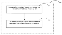
- FIG. 1 is a flow diagram of an example method for monitoring the tool rotation during a gyrocompassing survey measurement while the survey tool is at a location along the wellbore in accordance with certain embodiments described herein.
- FIG. 2 is a flow diagram of an example method for compensating for the tool rotation during a gyrocompassing survey measurement while the survey tool is at a location along the wellbore in accordance with certain embodiments described herein.
- FIG. 3A schematically illustrates an example system in accordance with certain embodiments described herein.
- FIG. 3B schematically illustrates another example system in accordance with certain embodiments described herein.
- gyrocompassing survey measurements e.g., gyroscopic measurements taken while the survey tool is substantially stationary to measure rotations due to the Earth's rotation
- examples of which include, but are not limited to, gyro-while-drilling (GWD) applications or measurement-while-drilling (MWD) applications.
- GWD gyro-while-drilling
- MWD measurement-while-drilling
- the systems and methods described herein may also be used in certain other types of static/gyrocompassing wellbore surveys as well, including, but not limited to, wireline surveys, slickline surveys (e.g., surveys run on a wireline without communication to the surface), and drop surveys.
- the situation downhole is not known precisely; and failure of the survey tool to become totally static when measurement data are collected may degrade the accuracy of the survey.
- the survey tool When conducting a gyrocompassing survey of a wellbore, it is desirable that the survey tool remains perfectly stationary with respect to the Earth while the data is collected. Being stationary ensures that the at least one gyroscopic sensor module of the survey tool is subject only to the rotational motion of the Earth while the measurements are being made.
- the at least one gyroscopic sensor module measures one or more components of the Earth's rotation vector, and these measurements are used, in combination with measurements of tool inclination and tool face angle, to compute the azimuth of the survey tool, and hence the azimuth (A) of the wellbore, at the location of the survey tool within the wellbore.
- the azimuth can be calculated using the following equation:
- A arctan ⁇ [ ⁇ Ex ⁇ cos ⁇ ⁇ ⁇ - ⁇ Ey ⁇ sin ⁇ ⁇ ⁇ ( ⁇ Ex ⁇ sin ⁇ ⁇ ⁇ + ⁇ Ey ⁇ cos ⁇ ⁇ ⁇ ) ⁇ cos ⁇ ⁇ I + ⁇ Ez ⁇ sin ⁇ ⁇ I ] ( 1 )
- ( ⁇ Ex , ⁇ Ey , ⁇ Ez ) are the orthogonal components of the Earth's rotation vector
- I is the inclination angle
- ⁇ is the tool face angle.
- the inclination angle and the tool face angle can be generated from measurements of the orthogonal components ( ⁇ x , ⁇ y , ⁇ z ) of the Earth's gravitation vector (e.g., provided by a triad of accelerometers mounted in the survey tool) as follows:
- the at least one gyroscopic sensor module of the survey tool measures the total rotation rate to which the survey tool is subjected.
- the rate gyroscopes of the at least one gyroscopic sensor module provide measurements of the Earth's rotation vector plus a small residual rotation of the survey tool in the wellbore.
- the small residual rotation will occur principally about the longitudinal (z) axis of the survey tool (e.g., as a result of torque that has built up in the tool string during the drilling process).
- the measured rotation rate may be expressed mathematically as follows:
- ⁇ BI B [ ⁇ x ⁇ y ⁇ z ] , ( 5 ) which is the vector sum of the Earth's rotation rate with respect to inertial space resolved in tool body axes:
- ⁇ BE B [ 0 0 ⁇ . ] , ( 7 )
- ⁇ is the Earth rotation rate
- ⁇ is the latitude at which the survey tool is located
- A is the azimuth
- I is the inclination angle
- ⁇ is the tool face angle
- ⁇ dot over ( ⁇ ) ⁇ is the rate of change of tool face angle about the longitudinal axis of the survey tool.
- Certain embodiments described herein provide a method of monitoring this tool rotation during gyrocompassing survey measurements. Certain embodiments described herein provide a method of compensating for this potential source of survey error from gyrocompassing survey measurements. Because any gyroscopic sensor measurements would be subject to both rotation contributions, a gyroscopic sensor measurement cannot be used to measure the tool face angle rotation rate contributed by the small residual rotation.
- Certain embodiments described herein provide a system comprising at least one accelerometer module, in addition to any gyro-while-drilling or measurement-while-drilling (GWD/MWD) sensor modules, to provide signals which can be used to monitor the tool rotation and/or compensate for survey errors due to the tool rotation, during gyrocompassing survey measurements.
- GWD/MWD measurement-while-drilling
- FIG. 1 is a flow diagram of an example method 100 for monitoring the tool rotation during a gyrocompassing survey measurement while the survey tool is at a location along the wellbore in accordance with certain embodiments described herein.
- the method 100 comprises receiving a first plurality of signals from at least one accelerometer module of the survey tool.
- the first plurality of signals from the at least one accelerometer module are indicative of measurements of the Earth's gravitation vector taken by the at least one accelerometer module while the survey tool is used for gyrocompassing at the location along the wellbore.
- the at least one accelerometer module can comprise one, two, three, or more accelerometer sensors (e.g., a triad of accelerometers) that provide signals indicative of three orthogonal components ( ⁇ x , ⁇ y , ⁇ z ) of the Earth's gravitation vector at the position of the at least one accelerometer module.
- accelerometer sensors e.g., a triad of accelerometers
- accelerometer sensors are capable of providing a desired level of measurement accuracy and resolution compatible with certain embodiments described herein. Examples include, but are not limited to, quartz flexure accelerometer sensors and microelectromechanical system (MEMS) devices.
- the measurement range may be in excess of ⁇ 1 g (e.g., in a range between ⁇ 1.2 g and ⁇ 1.5 g).
- the accelerometer sensors are advantageously sufficiently small to be accommodated in a down hole tool (e.g., within the confines of a 13 ⁇ 4-inch pressure case of a wellbore), capable of operating over the expected temperature range (e.g., ⁇ 20° C. to +150° C., or greater), and capable of surviving the down hole vibration and shock environment that will be encountered during the drilling process.
- the resolution and precision of the at least one accelerometer sensors can depend on the time and the desired angular rate uncertainty. For example, for errors below a maximum error on the toolface rate of 0.05°/hour over 15 seconds, the at least one accelerometer can provide noise levels below 0.14 mG. An analog-to-digital system with a range of ⁇ 1.2 G and 16 bits can give a resolution of 0.036 mG/count, which can satisfy the desired noise levels. If the time is increased, the accelerometer uncertainty can be increased as well.
- the survey tool comprises at least one accelerometer module comprising a plurality of accelerometers that is part of either a gyro-while-drilling (GWD) survey tool or a measurement-while-drilling (MWD) survey tool (e.g., for determining the inclination and tool face angles at various positions along the wellbore being surveyed).
- the first plurality of signals is provided by the at least one accelerometer module of the GWD/MWD survey tool.
- the survey tool comprises at least one accelerometer module different from the at least one accelerometer module of the GWD/MWD survey tool, and the first plurality of signals are provided by this at least one accelerometer module different from that of the GWD/MWD survey tool.
- the at least one accelerometer module can comprise one or more accelerometers that are dedicated to measurements of the Earth's gravitation vector during times at which the survey tool is used for gyrocompassing (e.g., that are not used for determining the inclination and tool face angles at various positions along the wellbore being surveyed, such as during gyrosteering measurements).
- the method 100 further comprises using the first plurality of signals to calculate a tool face rate of change with respect to the wellbore measured while the survey tool remains at the location along the wellbore.
- one or more signals indicative of the Earth's gravitation vector at time t k can be used, e.g., with equation (3), to calculate the measured tool face angle ⁇ k at time t k
- one or more signals indicative of the Earth's gravitation vector at later time t k+1 can be used, e.g., with equation (3), to calculate the measured tool face angle ⁇ k+1 at time t k+1 .
- the tool face rate of change ( ⁇ dot over ( ⁇ ) ⁇ k ) can then be calculated by computing the difference between successive calculations of the measured tool face angle and dividing by the time ( ⁇ t) between the successive measurements.
- the tool face rate at time step k can be expressed as:
- a sequence of measurements may be taken over a period of time, and these measurements may be averaged together to produce data for gyrocompassing.
- the accuracy of the tool face rate estimate generated in this way can increase if the time between successive tool face measurements ( ⁇ t) is increased.
- the total time available for such measurements may be restricted to a period of time deemed acceptable for performing the standard gyrocompassing operation (e.g., between 2 and 4 minutes in total). Note that taking measurements of the tool face rate over a longer period of time may be detrimental to performance since this rate may not be constant.
- a compromise may be reached in certain embodiments between increasing the total time for making the measurements to thereby increase the accuracy of the measurements and desiring to decrease the total time devoted to thereby provide perform quicker surveys.
- FIG. 2 is a flow diagram of an example method 200 for compensating for the tool rotation during a gyrocompassing survey measurement while the survey tool is at a location along the wellbore in accordance with certain embodiments described herein.
- the method 200 can comprise the operational blocks 110 and 120 as described above.
- the method 200 further comprises receiving a second plurality of signals from at least one gyroscopic sensor module of the survey tool.
- the second plurality of signals is indicative of the total rotation rate to which the survey tool is subjected during the gyrocompassing survey measurement.
- the at least one gyroscopic sensor module can comprise one or more gyroscopic sensors.
- Example gyroscopic sensors compatible with embodiments described herein are described more fully in “Survey Accuracy is Improved by a New, Small OD Gyro,” G. W. Uttecht, J. P. deWardt, World Oil, March 1983; U.S. Pat. Nos. 5,657,547, 5,821,414, and 5,806,195. These references are incorporated in their entireties by reference herein.
- Other examples of gyroscopic sensors are described by U.S. Pat. Nos. 6,347,282, 6,957,580, 7,117,605, 7,225,550, 7,234,539, 7,350,410, and 7,669,656 each of which is incorporated in its entirety by reference herein.
- the one or more gyroscopic sensors are advantageously capable of providing measurements of turn rate to the desired accuracy (e.g., in a range from 0.01°/hour to 0.05°/hour). Examples include, but are not limited to, spinning wheel gyros, optical gyros, and MEMS gyros.
- the one or more gyroscopic sensors are advantageously sufficiently small to be accommodated in a down hole tool (e.g., within the confines of a 13 ⁇ 4-inch pressure case of a wellbore), capable of operating over the expected temperature range (e.g., ⁇ 20° C. to +150° C., or greater), and capable of surviving the down hole vibration and shock environment that will be encountered during the drilling process.
- the method 200 further comprises using the second plurality of signals to calculate the total rotation rate to which the survey tool is subjected during the gyrocompassing survey measurement.
- the second plurality of signals are indicative of measurements of the total rate of rotation with respect to inertial space
- the method 200 further comprises subtracting the tool face rate of change with respect to the wellbore from the total rotation rate to which the survey tool is subjected during the gyrocompassing survey measurement.
- the tool face rate of change is subtracted from the component ( ⁇ z ) of the total rotation rate about the longitudinal (z) axis of the survey tool, e.g., using equations (4)-(7) above.
- subtracting the tool face rate of change from the total rotation rate is performed as part of a calibration correction process of the at least one gyroscopic sensor module.
- the component of the Earth's rotation rate about the longitudinal (z) axis of the survey tool can be determined and used to compute the azimuth at the corresponding sample time.
- FIG. 3A schematically illustrates an example system 300 in accordance with certain embodiments described herein
- FIG. 3B schematically illustrates another example system 300 in accordance with certain embodiments described herein
- the system 300 comprises a tool string 310 configured to be within a wellbore 312 and comprising a survey tool 320 configured to perform gyrocompassing surveys.
- the survey tool 320 can comprise at least one gyro-while-drilling (GWD) survey tool or at least one measurement-while-drilling (MWD) survey tool.
- GWD gyro-while-drilling
- MWD measurement-while-drilling
- the survey tool 320 comprises at least one gyroscopic sensor module 322 configured to generate a first one or more signals indicative of measurements of the total rotation rate to which the at least one gyroscopic sensor module 322 is exposed during a gyrocompassing survey.
- the total rotation rate comprises a first contribution due to the Earth's rotation vector and a second contribution due to rotation of the survey tool 320 during a gyrocompassing survey.
- the system 300 further comprises at least one accelerometer module 330 configured to generate a second one or more signals indicative of measurements of the Earth's gravitation vector at the at least one accelerometer module 330 .
- the at least one accelerometer module 330 is part of the survey tool 320 (e.g., the GWD survey tool or the MWD survey tool).
- the at least one accelerometer module 330 is separate from the survey tool 320 (e.g., the at least one accelerometer module 330 is in addition to at least one accelerometer module of the survey tool 320 ).
- the at least one accelerometer module 330 can comprise one or more accelerometers that are dedicated to measurements of the Earth's gravitation vector during times at which the survey tool 320 is used for gyrocompassing (e.g., that are not used for determining the inclination and tool face angles at various positions along the wellbore being surveyed).
- the at least one accelerometer module 330 comprises one or more cross-axial accelerometers configured to sense two or more components of the Earth's gravitation vector.
- the at least one accelerometer module 330 comprises two or more single-axis accelerometers, one or more two-axis accelerometers, and/or one or more three-axis accelerometers.
- Various types of accelerometer sensors are capable of providing a desired level of measurement accuracy and resolution compatible with certain embodiments described herein. Examples include, but are not limited to, quartz flexure accelerometer sensors and MEMS devices. The measurement range may be in excess of ⁇ 1 g (e.g., in a range between ⁇ 1.2 g and ⁇ 1.5 g).
- the accelerometer sensors are advantageously sufficiently small to be accommodated in a down hole tool (e.g., within the confines of a 13 ⁇ 4-inch pressure case of a wellbore), capable of operating over the expected temperature range (e.g., ⁇ 20° C. to +150° C., or greater), and capable of surviving the down hole vibration and shock environment that will be encountered during the drilling process.
- a down hole tool e.g., within the confines of a 13 ⁇ 4-inch pressure case of a wellbore
- the expected temperature range e.g., ⁇ 20° C. to +150° C., or greater
- the resolution and precision of the at least one accelerometer sensors can depend on the time and the desired angular rate uncertainty. For example, for errors below a maximum error on the toolface rate of 0.05°/hour over 15 seconds, the at least one accelerometer can provide noise levels below 0.14 mG. An analog-to-digital system with a range of ⁇ 1.2 G and 16 bits can give a resolution of 0.036 mG/count, which can satisfy the desired noise levels. If the time is increased, the accelerometer uncertainty can be increased as well.
- the system 300 further comprises at least one processor 340 (e.g., one or more micro-processors, a standard personal computer) configured to receive at least the first one or more signals and the second one or more signals.
- the at least one processor 340 is configured to determine the tool angle rotation rate in response to the second one or more signals (e.g., by performing the method 100 described herein).
- the at least one processor 340 is further configured to determine a rotation rate of the survey tool 320 compensated for the tool angle rotation rate in response to both the first one or more signals and the second one or more signals (e.g., by performing the method 200 described herein).
- the at least one processor 340 can be further configured to calculate a tool face rate of change about a longitudinal axis of the survey tool using the second one or more signals, and to subtract the tool face rate of change from the measured tool angle rotation rate to provide the rotation rate of the survey tool 320 compensated for the tool angle rotation rate.
- the at least one processor 340 can comprise one or more hardware processors in communication with at least one computer-readable memory that stores software modules including instructions that are executable by the one or more hardware processors.
- the software modules can include one or more software modules configured to receive a first plurality of signals from at least one accelerometer module 330 of the survey tool 320 (e.g., to perform the operational block 110 of the method 100 ) and to use the first plurality of signals to calculate a tool face rate of change with respect to the wellbore measured while the survey tool 320 remains at the location along the wellbore 312 (e.g., to perform the operational block 120 of the method 100 ).
- the one or more software modules can be further configured to receive a second plurality of signals from at least one gyroscopic sensor module 322 of the survey tool 320 (e.g., to perform the operational block 130 of the method 200 ), to use the second plurality of signals to calculate the total rotation rate to which the survey tool 320 is subjected during the gyrocompassing survey measurement (e.g., to perform the operational block 140 of the method 200 ), and to subtract the tool face rate of change with respect to the wellbore 312 from the total rotation rate to which the survey tool 320 is subjected during the gyrocompassing survey measurement (e.g., to perform the operational block 150 of the method 200 ).
- a second plurality of signals from at least one gyroscopic sensor module 322 of the survey tool 320 (e.g., to perform the operational block 130 of the method 200 ), to use the second plurality of signals to calculate the total rotation rate to which the survey tool 320 is subjected during the gyrocom
- a non-transitory computer storage can be provided having stored thereon a computer program that instructs a computer system (e.g., the at least one processor 340 ) to perform one or more methods (e.g., the method 100 , the method 200 ) compatible with certain embodiments described herein.
- a computer system e.g., the at least one processor 340
- methods e.g., the method 100 , the method 200
- the at least one processor 340 is part of a controller generally configured to control and/or monitor the operation of the tool string 310 or portions thereof, with the controller comprising hardware, software, or a combination of both hardware and software.
- the at least one processor 340 can be further configured to determine the current orientation or the trajectory of the drill string within the wellbore 312 .
- the at least one processor 340 can further be configured to communicate with a memory subsystem configured to store appropriate information, such as orientation data, data obtained from one or more sensor modules on the drill string, etc.
- the at least one processor 340 provides a real-time processing analysis of the signals or data obtained from various sensors of the survey tool 320 .
- data obtained from the various sensor modules are analyzed in real-time.
- at least a portion of the data obtained from the various sensor modules is saved in memory for analysis by the at least one processor 340 .
- the at least one processor 340 of certain such embodiments comprises sufficient data processing and data storage capacity to perform the real-time analysis.
- the at least one processor 340 is located at or above the Earth's surface (e.g., as schematically illustrated by FIGS. 3A and 3B ), or is located within the survey tool 320 within the wellbore. In some embodiments, a portion of the at least one processor 340 is located at or above the Earth's surface, and another portion of the at least one processor 340 is located within the wellbore and is communicatively coupled to the portion at or above the Earth's surface.
- the system and method described herein are advantageously relevant and useful for measurements taken in high inclination wellbores.
- the z-gyro measurement can have little effect on the calculation of azimuth, as indicated by equation (1). In such situations, the tool face rate can be expected to have little effect on the calculation.
- the z-gyro measurement can become very significant and any contribution to the rotation rate beyond that of the Earth's rate component which is to be measured can lead to a significant azimuth error, as discussed above.
- acts, events, or functions of any of the methods described herein can be performed in a different sequence, can be added, merged, or left out completely (e.g., not all described acts or events are necessary for the practice of the method).
- acts or events can be performed concurrently, e.g., through multi-threaded processing, interrupt processing, or multiple processors or processor cores, rather than sequentially.
- DSP digital signal processor
- ASIC application specific integrated circuit
- FPGA field programmable gate array
- a general purpose processor can be a microprocessor, but in the alternative, the processor can be any conventional processor, controller, microcontroller, or state machine.
- a processor can also be implemented as a combination of computing devices, e.g., a combination of a DSP and a microprocessor, a plurality of microprocessors, one or more microprocessors in conjunction with a DSP core, or any other such configuration.
- a software module can reside in RAM memory, flash memory, ROM memory, EPROM memory, EEPROM memory, registers, a hard disk, a removable disk, a CD-ROM, or any other form of computer-readable storage medium known in the art.
- An exemplary tangible, computer-readable storage medium is coupled to a processor such that the processor can read information from, and write information to, the storage medium.
- the storage medium can be integral to the processor.
- the processor and the storage medium can reside in an ASIC.
- the ASIC can reside in a user terminal.
- the processor and the storage medium can reside as discrete components in a user terminal.
Landscapes
- Physics & Mathematics (AREA)
- Engineering & Computer Science (AREA)
- Geology (AREA)
- Life Sciences & Earth Sciences (AREA)
- Mining & Mineral Resources (AREA)
- General Physics & Mathematics (AREA)
- Geophysics (AREA)
- Environmental & Geological Engineering (AREA)
- Fluid Mechanics (AREA)
- General Life Sciences & Earth Sciences (AREA)
- Geochemistry & Mineralogy (AREA)
- Radar, Positioning & Navigation (AREA)
- Remote Sensing (AREA)
- Gyroscopes (AREA)
Abstract
Description
where (ωEx, ωEy, ωEz) are the orthogonal components of the Earth's rotation vector, I is the inclination angle, and α is the tool face angle. The inclination angle and the tool face angle can be generated from measurements of the orthogonal components (αx, αy, αz) of the Earth's gravitation vector (e.g., provided by a triad of accelerometers mounted in the survey tool) as follows:
The total rotation rate with respect to inertial space measured by the rate gyroscopes of the at least one gyroscopic sensor module can be expressed as:
which is the vector sum of the Earth's rotation rate with respect to inertial space resolved in tool body axes:
and the rotation rate of the tool body with respect to the Earth, expressed in tool body axes:
where Ω is the Earth rotation rate, φ is the latitude at which the survey tool is located, A is the azimuth, I is the inclination angle, α is the tool face angle, and {dot over (α)} is the rate of change of tool face angle about the longitudinal axis of the survey tool.
Other calculations of the tool face rate of change using the first plurality of signals are also compatible with certain embodiments described herein.
Claims (18)
Priority Applications (4)
| Application Number | Priority Date | Filing Date | Title |
|---|---|---|---|
| US14/245,784 US9631475B2 (en) | 2014-04-04 | 2014-04-04 | System and method for monitoring tool rotation during a gyrocompassing wellbore survey |
| CA2884626A CA2884626C (en) | 2014-04-04 | 2015-03-10 | System and method for monitoring tool rotation during a gyrocompassing wellbore survey |
| MX2015004147A MX2015004147A (en) | 2014-04-04 | 2015-03-31 | System and method for monitoring tool rotation during a gyrocompassing wellbore survey. |
| EP15162450.9A EP2927419B1 (en) | 2014-04-04 | 2015-04-02 | System and method for monitoring tool rotation during a gyrocompassing wellbore survey |
Applications Claiming Priority (1)
| Application Number | Priority Date | Filing Date | Title |
|---|---|---|---|
| US14/245,784 US9631475B2 (en) | 2014-04-04 | 2014-04-04 | System and method for monitoring tool rotation during a gyrocompassing wellbore survey |
Publications (2)
| Publication Number | Publication Date |
|---|---|
| US20150285056A1 US20150285056A1 (en) | 2015-10-08 |
| US9631475B2 true US9631475B2 (en) | 2017-04-25 |
Family
ID=52807722
Family Applications (1)
| Application Number | Title | Priority Date | Filing Date |
|---|---|---|---|
| US14/245,784 Active 2034-09-01 US9631475B2 (en) | 2014-04-04 | 2014-04-04 | System and method for monitoring tool rotation during a gyrocompassing wellbore survey |
Country Status (4)
| Country | Link |
|---|---|
| US (1) | US9631475B2 (en) |
| EP (1) | EP2927419B1 (en) |
| CA (1) | CA2884626C (en) |
| MX (1) | MX2015004147A (en) |
Cited By (5)
| Publication number | Priority date | Publication date | Assignee | Title |
|---|---|---|---|---|
| WO2018231969A1 (en) * | 2017-06-14 | 2018-12-20 | Gyrodata, Incorporated | Gyro-magnetic wellbore surveying |
| US11175431B2 (en) | 2017-06-14 | 2021-11-16 | Gyrodata, Incorporated | Gyro-magnetic wellbore surveying |
| US11193363B2 (en) | 2017-12-04 | 2021-12-07 | Gyrodata, Incorporated | Steering control of a drilling tool |
| US12012847B2 (en) | 2020-12-10 | 2024-06-18 | Gyrodata, Incorporated | System and method for using a magnetometer in a gyro-while-drilling survey tool |
| US20250290402A1 (en) * | 2024-03-12 | 2025-09-18 | Schlumberger Technology Corporation | Downhole gyroscopic surveying measurements under dynamic conditions |
Families Citing this family (1)
| Publication number | Priority date | Publication date | Assignee | Title |
|---|---|---|---|---|
| EP4460619A4 (en) | 2022-01-04 | 2025-11-19 | Services Petroliers Schlumberger | SYSTEMS AND METHODS FOR AZIMUTH DETERMINATION DURING DRILLING |
Citations (14)
| Publication number | Priority date | Publication date | Assignee | Title |
|---|---|---|---|---|
| US5657547A (en) * | 1994-12-19 | 1997-08-19 | Gyrodata, Inc. | Rate gyro wells survey system including nulling system |
| US5821414A (en) * | 1997-02-07 | 1998-10-13 | Noy; Koen | Survey apparatus and methods for directional wellbore wireline surveying |
| US6347282B2 (en) * | 1997-12-04 | 2002-02-12 | Baker Hughes Incorporated | Measurement-while-drilling assembly using gyroscopic devices and methods of bias removal |
| US6381858B1 (en) * | 2000-09-22 | 2002-05-07 | Schlumberger Technology Corporation | Method for calculating gyroscopic wellbore surveys including correction for unexpected instrument movement |
| US20030056381A1 (en) * | 1997-02-07 | 2003-03-27 | James Brosnahan | Survey apparatus and methods for directional wellbore surveying |
| US6957580B2 (en) * | 2004-01-26 | 2005-10-25 | Gyrodata, Incorporated | System and method for measurements of depth and velocity of instrumentation within a wellbore |
| US20050268476A1 (en) * | 2004-06-07 | 2005-12-08 | Pathfinder Energy Services, Inc. | Determining a borehole azimuth from tool face measurements |
| US7117605B2 (en) * | 2004-04-13 | 2006-10-10 | Gyrodata, Incorporated | System and method for using microgyros to measure the orientation of a survey tool within a borehole |
| US7234539B2 (en) * | 2003-07-10 | 2007-06-26 | Gyrodata, Incorporated | Method and apparatus for rescaling measurements while drilling in different environments |
| US20100100329A1 (en) * | 2008-10-22 | 2010-04-22 | Gyrodata, Incorporated | Downhole surveying utilizing multiple measurements |
| US20110011646A1 (en) * | 2000-04-13 | 2011-01-20 | Giroux Richard L | Apparatus and methods for drilling a wellbore using casing |
| US8065085B2 (en) * | 2007-10-02 | 2011-11-22 | Gyrodata, Incorporated | System and method for measuring depth and velocity of instrumentation within a wellbore using a bendable tool |
| US8185312B2 (en) * | 2008-10-22 | 2012-05-22 | Gyrodata, Incorporated | Downhole surveying utilizing multiple measurements |
| US20130211723A1 (en) * | 2009-01-30 | 2013-08-15 | Gyrodata, Incorporated | Reducing error contributions to gyroscopic measurements |
-
2014
- 2014-04-04 US US14/245,784 patent/US9631475B2/en active Active
-
2015
- 2015-03-10 CA CA2884626A patent/CA2884626C/en active Active
- 2015-03-31 MX MX2015004147A patent/MX2015004147A/en unknown
- 2015-04-02 EP EP15162450.9A patent/EP2927419B1/en active Active
Patent Citations (18)
| Publication number | Priority date | Publication date | Assignee | Title |
|---|---|---|---|---|
| US5657547A (en) * | 1994-12-19 | 1997-08-19 | Gyrodata, Inc. | Rate gyro wells survey system including nulling system |
| US5806195A (en) | 1994-12-19 | 1998-09-15 | Uttecht; Gary | Rate gyro wells survey system including nulling system |
| US5821414A (en) * | 1997-02-07 | 1998-10-13 | Noy; Koen | Survey apparatus and methods for directional wellbore wireline surveying |
| US20030056381A1 (en) * | 1997-02-07 | 2003-03-27 | James Brosnahan | Survey apparatus and methods for directional wellbore surveying |
| US6347282B2 (en) * | 1997-12-04 | 2002-02-12 | Baker Hughes Incorporated | Measurement-while-drilling assembly using gyroscopic devices and methods of bias removal |
| US20110011646A1 (en) * | 2000-04-13 | 2011-01-20 | Giroux Richard L | Apparatus and methods for drilling a wellbore using casing |
| US6381858B1 (en) * | 2000-09-22 | 2002-05-07 | Schlumberger Technology Corporation | Method for calculating gyroscopic wellbore surveys including correction for unexpected instrument movement |
| US7669656B2 (en) | 2003-07-10 | 2010-03-02 | Gyrodata, Incorporated | Method and apparatus for rescaling measurements while drilling in different environments |
| US7234539B2 (en) * | 2003-07-10 | 2007-06-26 | Gyrodata, Incorporated | Method and apparatus for rescaling measurements while drilling in different environments |
| US7350410B2 (en) * | 2004-01-26 | 2008-04-01 | Gyrodata, Inc. | System and method for measurements of depth and velocity of instrumentation within a wellbore |
| US6957580B2 (en) * | 2004-01-26 | 2005-10-25 | Gyrodata, Incorporated | System and method for measurements of depth and velocity of instrumentation within a wellbore |
| US7117605B2 (en) * | 2004-04-13 | 2006-10-10 | Gyrodata, Incorporated | System and method for using microgyros to measure the orientation of a survey tool within a borehole |
| US7225550B2 (en) * | 2004-04-13 | 2007-06-05 | Gyrodata Incorporated | System and method for using microgyros to measure the orientation of a survey tool within a borehole |
| US20050268476A1 (en) * | 2004-06-07 | 2005-12-08 | Pathfinder Energy Services, Inc. | Determining a borehole azimuth from tool face measurements |
| US8065085B2 (en) * | 2007-10-02 | 2011-11-22 | Gyrodata, Incorporated | System and method for measuring depth and velocity of instrumentation within a wellbore using a bendable tool |
| US20100100329A1 (en) * | 2008-10-22 | 2010-04-22 | Gyrodata, Incorporated | Downhole surveying utilizing multiple measurements |
| US8185312B2 (en) * | 2008-10-22 | 2012-05-22 | Gyrodata, Incorporated | Downhole surveying utilizing multiple measurements |
| US20130211723A1 (en) * | 2009-01-30 | 2013-08-15 | Gyrodata, Incorporated | Reducing error contributions to gyroscopic measurements |
Non-Patent Citations (1)
| Title |
|---|
| Uttecht, et al.; Survey Accuracy is Improved by a New, Small OD Gyro; World Oil; Mar. 1983. |
Cited By (8)
| Publication number | Priority date | Publication date | Assignee | Title |
|---|---|---|---|---|
| WO2018231969A1 (en) * | 2017-06-14 | 2018-12-20 | Gyrodata, Incorporated | Gyro-magnetic wellbore surveying |
| US11041376B2 (en) | 2017-06-14 | 2021-06-22 | Gyrodata, Incorporated | Gyro-magnetic wellbore surveying |
| US11175431B2 (en) | 2017-06-14 | 2021-11-16 | Gyrodata, Incorporated | Gyro-magnetic wellbore surveying |
| US11193363B2 (en) | 2017-12-04 | 2021-12-07 | Gyrodata, Incorporated | Steering control of a drilling tool |
| US12012847B2 (en) | 2020-12-10 | 2024-06-18 | Gyrodata, Incorporated | System and method for using a magnetometer in a gyro-while-drilling survey tool |
| US12392237B2 (en) | 2020-12-10 | 2025-08-19 | Gyrodata, Incorporated | System and method for using a magnetometer in a gyro-while-drilling survey tool |
| US20250290402A1 (en) * | 2024-03-12 | 2025-09-18 | Schlumberger Technology Corporation | Downhole gyroscopic surveying measurements under dynamic conditions |
| US12473817B2 (en) * | 2024-03-12 | 2025-11-18 | Schlumberger Technology Corporation | Downhole gyroscopic surveying measurements under dynamic conditions |
Also Published As
| Publication number | Publication date |
|---|---|
| US20150285056A1 (en) | 2015-10-08 |
| CA2884626A1 (en) | 2015-10-04 |
| MX2015004147A (en) | 2015-10-05 |
| CA2884626C (en) | 2017-11-28 |
| EP2927419A1 (en) | 2015-10-07 |
| EP2927419B1 (en) | 2019-09-04 |
Similar Documents
| Publication | Publication Date | Title |
|---|---|---|
| US8374793B2 (en) | Reducing error contributions to gyroscopic measurements from a wellbore survey system | |
| US10077648B2 (en) | System and method for providing a continuous wellbore survey | |
| US9631475B2 (en) | System and method for monitoring tool rotation during a gyrocompassing wellbore survey | |
| US10309799B2 (en) | Correction of rotation rate measurements | |
| US10781691B2 (en) | System and method for providing a continuous wellbore survey | |
| US10550686B2 (en) | Tumble gyro surveyor | |
| US20130211723A1 (en) | Reducing error contributions to gyroscopic measurements | |
| US10689969B2 (en) | System and method for providing a continuous wellbore survey | |
| US20190330979A1 (en) | System and Method for Providing a Continuous Wellbore Survey | |
| US12392237B2 (en) | System and method for using a magnetometer in a gyro-while-drilling survey tool | |
| US20200132458A1 (en) | Wellbore Survey Tool Using Coriolis Vibratory Gyroscopic Sensors | |
| EP2759674A2 (en) | Reducing error contributions to gyroscopic measurements | |
| US11002131B2 (en) | Directional control of wellbore trajectories | |
| US20210026037A1 (en) | Wellbore Survey Tool Using Coriolis Vibratory Gyroscopic Sensors | |
| Weston et al. | New gyro while drilling technology delivers accurate azimuth and real-time quality control for all well trajectories | |
| NO20191255A1 (en) | Continuous survey using magnetic sensors | |
| US20180364389A1 (en) | Gyro-Magnetic Wellbore Surveying | |
| US20200072038A1 (en) | Reducing error contributions to gyroscopic measurements | |
| WO2019006410A1 (en) | System and method for providing a continuous wellbore survey | |
| WO2019006411A1 (en) | Continuous survey using survey sensors | |
| NO20191187A1 (en) | System and method for providing a continuous wellbore survey |
Legal Events
| Date | Code | Title | Description |
|---|---|---|---|
| AS | Assignment |
Owner name: GYRODATA, INCORPORATED, TEXAS Free format text: ASSIGNMENT OF ASSIGNORS INTEREST;ASSIGNORS:LEDROZ, ADRIAN GUILLERMO;JOHNSON, JAMES MICHAEL;REEL/FRAME:032703/0975 Effective date: 20140417 |
|
| STCF | Information on status: patent grant |
Free format text: PATENTED CASE |
|
| MAFP | Maintenance fee payment |
Free format text: PAYMENT OF MAINTENANCE FEE, 4TH YEAR, LARGE ENTITY (ORIGINAL EVENT CODE: M1551); ENTITY STATUS OF PATENT OWNER: LARGE ENTITY Year of fee payment: 4 |
|
| MAFP | Maintenance fee payment |
Free format text: PAYMENT OF MAINTENANCE FEE, 8TH YEAR, LARGE ENTITY (ORIGINAL EVENT CODE: M1552); ENTITY STATUS OF PATENT OWNER: LARGE ENTITY Year of fee payment: 8 |