US9627786B2 - Electrical connector with improved contacts - Google Patents
Electrical connector with improved contacts Download PDFInfo
- Publication number
- US9627786B2 US9627786B2 US14/695,064 US201514695064A US9627786B2 US 9627786 B2 US9627786 B2 US 9627786B2 US 201514695064 A US201514695064 A US 201514695064A US 9627786 B2 US9627786 B2 US 9627786B2
- Authority
- US
- United States
- Prior art keywords
- electrical connector
- frame
- accessory
- receiving space
- extending
- Prior art date
- Legal status (The legal status is an assumption and is not a legal conclusion. Google has not performed a legal analysis and makes no representation as to the accuracy of the status listed.)
- Expired - Fee Related, expires
Links
Images


Classifications
-
- H—ELECTRICITY
- H01—ELECTRIC ELEMENTS
- H01R—ELECTRICALLY-CONDUCTIVE CONNECTIONS; STRUCTURAL ASSOCIATIONS OF A PLURALITY OF MUTUALLY-INSULATED ELECTRICAL CONNECTING ELEMENTS; COUPLING DEVICES; CURRENT COLLECTORS
- H01R12/00—Structural associations of a plurality of mutually-insulated electrical connecting elements, specially adapted for printed circuits, e.g. printed circuit boards [PCB], flat or ribbon cables, or like generally planar structures, e.g. terminal strips, terminal blocks; Coupling devices specially adapted for printed circuits, flat or ribbon cables, or like generally planar structures; Terminals specially adapted for contact with, or insertion into, printed circuits, flat or ribbon cables, or like generally planar structures
- H01R12/70—Coupling devices
- H01R12/71—Coupling devices for rigid printing circuits or like structures
- H01R12/712—Coupling devices for rigid printing circuits or like structures co-operating with the surface of the printed circuit or with a coupling device exclusively provided on the surface of the printed circuit
- H01R12/716—Coupling device provided on the PCB
-
- H—ELECTRICITY
- H01—ELECTRIC ELEMENTS
- H01R—ELECTRICALLY-CONDUCTIVE CONNECTIONS; STRUCTURAL ASSOCIATIONS OF A PLURALITY OF MUTUALLY-INSULATED ELECTRICAL CONNECTING ELEMENTS; COUPLING DEVICES; CURRENT COLLECTORS
- H01R12/00—Structural associations of a plurality of mutually-insulated electrical connecting elements, specially adapted for printed circuits, e.g. printed circuit boards [PCB], flat or ribbon cables, or like generally planar structures, e.g. terminal strips, terminal blocks; Coupling devices specially adapted for printed circuits, flat or ribbon cables, or like generally planar structures; Terminals specially adapted for contact with, or insertion into, printed circuits, flat or ribbon cables, or like generally planar structures
- H01R12/70—Coupling devices
- H01R12/7076—Coupling devices for connection between PCB and component, e.g. display
-
- H—ELECTRICITY
- H01—ELECTRIC ELEMENTS
- H01R—ELECTRICALLY-CONDUCTIVE CONNECTIONS; STRUCTURAL ASSOCIATIONS OF A PLURALITY OF MUTUALLY-INSULATED ELECTRICAL CONNECTING ELEMENTS; COUPLING DEVICES; CURRENT COLLECTORS
- H01R13/00—Details of coupling devices of the kinds covered by groups H01R12/70 or H01R24/00 - H01R33/00
- H01R13/62—Means for facilitating engagement or disengagement of coupling parts or for holding them in engagement
- H01R13/627—Snap or like fastening
Definitions
- the present invention relates to electrical connectors, more particularly to an electrical connector being mounted with an accessory element.
- Electrical connectors are widely used in electronic equipments, such as computers.
- An electrical connector for connecting a module with a printed circuit board or connecting two modules usually has a body with a space for receiving the module.
- the module and the electrical connector are designed to be more and more smaller, sometime the electrical connector even needs to contain some other mini accessories therein, then it becomes a difficult thing to pick the mini accessories from the electrical connector.
- an electrical connector adapted for receiving an accessory, comprises a body, a locking arm and a frame.
- the body has a seat with a receiving space, and the locking arm extends from a peripheral of the seat toward the receiving space for retaining the accessory received in the receiving space.
- the locking arm is able to deflect outwardly for releasing the accessory.
- the frame surrounds the body, and has an elastic pushing arm which extends into the receiving space from a bottom side for upwardly pushing the accessory.
- FIG. 1 is an assembled, perspective view of an electrical connector according to the present invention and being mounted on a printed circuit board, wherein an electronic component and an accessory are received in the electrical connector;
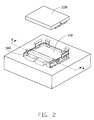
- FIG. 2 is another assembled, perspective view of the electrical connector mounted on the printed circuit board, wherein the electronic component is taken out from the electrical connector;
- FIG. 3 is similar with FIG. 2 , and wherein the accessory is further removed from the electronic component;
- FIG. 4 is an explored, perspective view of the electrical connector and the accessory in FIG. 3 ;
- FIG. 5 is an enlarged view of the circuited part in FIG. 3 ;
- FIG. 6 is a sectional view of the electrical connector, the printed circuit board, the electronic component and the accessory taken from line 6 - 6 in FIG. 2 .
- the electrical connector 100 in accordance with present invention, adapted for electrically connecting an electronic component 200 on printed circuit board 6 , receiving an accessory 300 .
- the electrical connector 100 has a body or housing 1 and a frame 2 surrounding the body 1 , and the body 1 has a socket 11 for receiving the electronic component 200 and a seat 12 for receiving the accessory 300 .
- the socket 11 has a bottom wall 110 , a plurality of sidewalls 111 extending from a peripheral of the bottom wall 110 and a plurality of contacts 3 disposed on the bottom wall 110 , only one is shown in FIG. 4 here for reference.
- the bottom wall 110 and the sidewalls 111 cooperatively define a receiving cavity 112 for receiving the electronic component 200 .
- the contact 3 expands into the receiving cavity 112 to electrically connect with the electronic component 200 .
- the electronic component 200 is a photoelectric modular, which can transmit signals with both the contacts 3 and the accessory 300 .
- the seat 12 is set beside the socket 11 , and is integrated with the socket 11 in present invention, in face the seat 12 and the socket 11 also can be disposed separately.
- the seat 12 has a base 120 and a plurality of blocking walls 121 extending upwardly from the base 120 , the base 120 and the blocking wall 121 together define a receiving space 122 for receiving the accessory 300 spaced from the receiving cavity 112 in a front-to-back direction.
- the receiving space 122 and the receiving cavity 112 are separated by the sidewall 111 , the receiving space 122 has a small dimension other than the receiving cavity 112 , the receiving space 122 has an opening opposite to the receiving cavity 112 , through which the accessory 300 extends out the electrical connector 100 for connecting with other component outside the electrical connector 100 .
- the base 120 of the seat 12 has a pair of recesses 1201 passing through the base 120 along a top to bottom direction near the blocking walls 121 .
- Two opposite of the blocking walls 121 of the seat 12 are opposite to each other in a transverse direction, and each of the blocking walls forms a locking arm 14 , correspondingly to the recess 1201 , the locking arm 14 has a latching portion 140 extending into the receiving space 122 and an operation portion 141 connecting with the latching portion 140 and located outside the latching portion 140 .
- the operation portion 141 brings the latching portion 140 to deflect outwardly when being pressed.
- the latching portion 140 has an inclined guiding surface 1400 for guiding the accessory 300 into the receiving space 122 .
- the frame 2 is a metallic piece, and has a U-shaped configuration with a mouth.
- the frame 2 has a main case 20 , a plurality of supporting legs 21 extending from a bottom of the main case 20 and a plurality of latching or retaining pieces 23 extending from a top of the main case 20 and used for latching with the electronic component 200 or easily assembling with the body 1 .
- the frame 2 further has a pair of pushing or pressing arms 22 extending from the bottom of the main base 20 and aslant upwardly and inwardly, corresponding to the positions of the recesses 1201 of the seat 12 for deflection in a vertical direction.
- the frame 2 is put out side the body 1 , the main case 20 surrounds the sidewalls 111 and the blocking walls 121 , the mouth of the is aligned with the opening of the receiving space 122 .
- the pushing arms 22 pass through the recesses 1201 of the base 120 of the seat 12 , and are located under corresponding latching arm 14 .
- the guiding face 1400 of the latching arm 14 guides the accessory 300 into the receiving space 122 of the seat 12 from a top side. Then, the accessory 300 downwardly pushes the pressing arm 22 , and a step 301 formed on an outside face of the accessory 300 is latched by the latching portion 140 of the latching arm 14 .
- the pressing arm 22 restores and upwardly pushes the accessory 300 from the receiving space 133 , and then the operator can easily pick up the accessory 300 .
Landscapes
- Details Of Connecting Devices For Male And Female Coupling (AREA)
- Connector Housings Or Holding Contact Members (AREA)
Abstract
Description
Claims (18)
Applications Claiming Priority (3)
| Application Number | Priority Date | Filing Date | Title |
|---|---|---|---|
| TW103207259U TWM490137U (en) | 2014-04-25 | 2014-04-25 | Electrical connector |
| TW103207259 | 2014-04-25 | ||
| TW103207259U | 2014-04-25 |
Publications (2)
| Publication Number | Publication Date |
|---|---|
| US20150311626A1 US20150311626A1 (en) | 2015-10-29 |
| US9627786B2 true US9627786B2 (en) | 2017-04-18 |
Family
ID=54335636
Family Applications (1)
| Application Number | Title | Priority Date | Filing Date |
|---|---|---|---|
| US14/695,064 Expired - Fee Related US9627786B2 (en) | 2014-04-25 | 2015-04-24 | Electrical connector with improved contacts |
Country Status (2)
| Country | Link |
|---|---|
| US (1) | US9627786B2 (en) |
| TW (1) | TWM490137U (en) |
Citations (3)
| Publication number | Priority date | Publication date | Assignee | Title |
|---|---|---|---|---|
| US6093039A (en) * | 1998-08-06 | 2000-07-25 | Mobility Electronics, Inc. | Docking device for a portable computer |
| US6406309B1 (en) * | 2000-09-29 | 2002-06-18 | International Business Machines Corporation | Enhanced arrangement for disengaging and separating two mated components |
| US6955549B2 (en) * | 2003-05-28 | 2005-10-18 | One World Technologies Limited | Slide type battery ejection mechanism |
-
2014
- 2014-04-25 TW TW103207259U patent/TWM490137U/en not_active IP Right Cessation
-
2015
- 2015-04-24 US US14/695,064 patent/US9627786B2/en not_active Expired - Fee Related
Patent Citations (3)
| Publication number | Priority date | Publication date | Assignee | Title |
|---|---|---|---|---|
| US6093039A (en) * | 1998-08-06 | 2000-07-25 | Mobility Electronics, Inc. | Docking device for a portable computer |
| US6406309B1 (en) * | 2000-09-29 | 2002-06-18 | International Business Machines Corporation | Enhanced arrangement for disengaging and separating two mated components |
| US6955549B2 (en) * | 2003-05-28 | 2005-10-18 | One World Technologies Limited | Slide type battery ejection mechanism |
Also Published As
| Publication number | Publication date |
|---|---|
| TWM490137U (en) | 2014-11-11 |
| US20150311626A1 (en) | 2015-10-29 |
Similar Documents
| Publication | Publication Date | Title |
|---|---|---|
| US9502815B2 (en) | Electrical connector | |
| JP6068405B2 (en) | Electrical connector assembly | |
| US8961215B2 (en) | Electrical connector assembled component, plug connector, and receptacle connector | |
| KR101990508B1 (en) | Plug connector | |
| US8292634B2 (en) | Socket connector having a recess provided with a spring member on a side thereof | |
| US8215976B2 (en) | Power adapter with replaceable plug | |
| US8079864B2 (en) | Electronic apparatus having a cover which synchronously defined as a wall of a modular jack disposed thereof | |
| US20080188103A1 (en) | Electrical connector assembly with improved pick-up cap | |
| CN100375339C (en) | Socket Type Electrical Connector | |
| TWI688171B (en) | Connector | |
| TW202008658A (en) | Connector assembly | |
| KR102734053B1 (en) | Socket connector | |
| US7367815B2 (en) | Electrical socket | |
| JP5659212B2 (en) | Circuit board electrical connector | |
| CN104901060A (en) | Socket connector | |
| TW201330389A (en) | Electrical connector, electronic apparatus using the same and metod for assembling the electrical connector | |
| US20150207269A1 (en) | Card connector with metallic retaining plate | |
| TW201630272A (en) | Electrical connector assembly | |
| US9627786B2 (en) | Electrical connector with improved contacts | |
| KR101942811B1 (en) | Socket connector and plug connector | |
| JP4774956B2 (en) | Connector and connector receptacle | |
| US9281592B2 (en) | Female connector and card edge connector | |
| KR101812421B1 (en) | Connector for electrically connecting electronic parts | |
| US20100291777A1 (en) | Elelctrical connector assembly with notch for receiving mating component | |
| JP2015028953A (en) | Plug connector and receptacle connector |
Legal Events
| Date | Code | Title | Description |
|---|---|---|---|
| AS | Assignment |
Owner name: FOXCONN INTERCONNECT TECHNOLOGY LIMITED, CAYMAN IS Free format text: ASSIGNMENT OF ASSIGNORS INTEREST;ASSIGNOR:HSU, SHUO-HSIU;REEL/FRAME:035485/0556 Effective date: 20150421 |
|
| STCF | Information on status: patent grant |
Free format text: PATENTED CASE |
|
| MAFP | Maintenance fee payment |
Free format text: PAYMENT OF MAINTENANCE FEE, 4TH YEAR, LARGE ENTITY (ORIGINAL EVENT CODE: M1551); ENTITY STATUS OF PATENT OWNER: LARGE ENTITY Year of fee payment: 4 |
|
| FEPP | Fee payment procedure |
Free format text: MAINTENANCE FEE REMINDER MAILED (ORIGINAL EVENT CODE: REM.); ENTITY STATUS OF PATENT OWNER: LARGE ENTITY |
|
| LAPS | Lapse for failure to pay maintenance fees |
Free format text: PATENT EXPIRED FOR FAILURE TO PAY MAINTENANCE FEES (ORIGINAL EVENT CODE: EXP.); ENTITY STATUS OF PATENT OWNER: LARGE ENTITY |
|
| STCH | Information on status: patent discontinuation |
Free format text: PATENT EXPIRED DUE TO NONPAYMENT OF MAINTENANCE FEES UNDER 37 CFR 1.362 |
|
| FP | Lapsed due to failure to pay maintenance fee |
Effective date: 20250418 |