US9627160B1 - Systems and methods for rotary knob friction adjustment control - Google Patents
Systems and methods for rotary knob friction adjustment control Download PDFInfo
- Publication number
- US9627160B1 US9627160B1 US15/040,343 US201615040343A US9627160B1 US 9627160 B1 US9627160 B1 US 9627160B1 US 201615040343 A US201615040343 A US 201615040343A US 9627160 B1 US9627160 B1 US 9627160B1
- Authority
- US
- United States
- Prior art keywords
- rotary knob
- knob
- circuit breaker
- housing
- opening
- Prior art date
- Legal status (The legal status is an assumption and is not a legal conclusion. Google has not performed a legal analysis and makes no representation as to the accuracy of the status listed.)
- Expired - Fee Related
Links
Images


Classifications
-
- H—ELECTRICITY
- H01—ELECTRIC ELEMENTS
- H01H—ELECTRIC SWITCHES; RELAYS; SELECTORS; EMERGENCY PROTECTIVE DEVICES
- H01H19/00—Switches operated by an operating part which is rotatable about a longitudinal axis thereof and which is acted upon directly by a solid body external to the switch, e.g. by a hand
- H01H19/02—Details
- H01H19/04—Cases; Covers
-
- H—ELECTRICITY
- H01—ELECTRIC ELEMENTS
- H01H—ELECTRIC SWITCHES; RELAYS; SELECTORS; EMERGENCY PROTECTIVE DEVICES
- H01H71/00—Details of the protective switches or relays covered by groups H01H73/00 - H01H83/00
- H01H71/10—Operating or release mechanisms
- H01H71/12—Automatic release mechanisms with or without manual release
- H01H71/40—Combined electrothermal and electromagnetic mechanisms
-
- H—ELECTRICITY
- H01—ELECTRIC ELEMENTS
- H01H—ELECTRIC SWITCHES; RELAYS; SELECTORS; EMERGENCY PROTECTIVE DEVICES
- H01H9/00—Details of switching devices, not covered by groups H01H1/00 - H01H7/00
- H01H9/02—Bases, casings, or covers
- H01H9/0207—Adjustable mounting of casings
-
- H—ELECTRICITY
- H01—ELECTRIC ELEMENTS
- H01H—ELECTRIC SWITCHES; RELAYS; SELECTORS; EMERGENCY PROTECTIVE DEVICES
- H01H19/00—Switches operated by an operating part which is rotatable about a longitudinal axis thereof and which is acted upon directly by a solid body external to the switch, e.g. by a hand
- H01H19/02—Details
- H01H19/10—Movable parts; Contacts mounted thereon
- H01H19/14—Operating parts, e.g. turn knob
-
- H—ELECTRICITY
- H01—ELECTRIC ELEMENTS
- H01H—ELECTRIC SWITCHES; RELAYS; SELECTORS; EMERGENCY PROTECTIVE DEVICES
- H01H71/00—Details of the protective switches or relays covered by groups H01H73/00 - H01H83/00
- H01H71/02—Housings; Casings; Bases; Mountings
- H01H71/025—Constructional details of housings or casings not concerning the mounting or assembly of the different internal parts
- H01H71/0257—Strength considerations
-
- H—ELECTRICITY
- H01—ELECTRIC ELEMENTS
- H01H—ELECTRIC SWITCHES; RELAYS; SELECTORS; EMERGENCY PROTECTIVE DEVICES
- H01H71/00—Details of the protective switches or relays covered by groups H01H73/00 - H01H83/00
- H01H71/74—Means for adjusting the conditions under which the device will function to provide protection
- H01H71/7418—Adjusting both electrothermal and electromagnetic mechanism
-
- H—ELECTRICITY
- H01—ELECTRIC ELEMENTS
- H01H—ELECTRIC SWITCHES; RELAYS; SELECTORS; EMERGENCY PROTECTIVE DEVICES
- H01H2235/00—Springs
- H01H2235/01—Spiral spring
Definitions
- aspects of the present invention generally relate to rotary knob friction adjustment control and more specifically relates to controlling rotational positions of knobs in a trip unit of a circuit breaker by friction, force, and/or pressure.
- rotary knobs to provide a mechanical control of some parameter is well known. This control is enabled by providing finite rotational positions of the knobs.
- the rotational positions can be controlled by friction, force, and/or pressure.
- control of rotational positions of knobs may be needed in a trip unit of a circuit breaker.
- the trip unit housings have been usually designed as two halves (two structural parts) split right through the centre of rotation of the knobs. These two halves, knobs and flat step operation springs are put together as a blind assembly. Knob control can be done with dents on the knobs. Dents may be crescent-shaped grooves being paired with corresponding plastic flexible fingers snapping in the grove for predetermined rotational knob position. All parts (knobs and housing halves) are usually hard plastic injection molded parts, but tight tolerances are necessary to make such an assembly possible. However, the tight tolerances made assemblies more expensive.
- aspects of the present invention relate to a friction adjustment control system configured to continuously control multiple rotational positions of a rotary knob in a trip unit of a circuit breaker by friction, force, and/or pressure.
- a spring may be installed in a housing against a structural support to apply a force onto the housing such that the housing presses directly against one or more smooth rings of the rotary knob.
- the spring may be a coiled spring.
- a spring may be installed in a pair of slots to apply a force directly against one or more smooth rings of the rotary knob.
- the spring may be a flat spring having a smooth perimeter.
- the flat spring can be of a symmetrical or an asymmetrical shape.
- a circuit breaker comprises a trip unit including an internal support.
- the internal support includes a first opening to receive a first rotary knob having one or more first smooth rings and a second opening to receive a second rotary knob having one or more second smooth rings.
- the circuit breaker further comprises a first knob control of the first rotary knob.
- the first knob control includes a first structural support, a first housing and a first spring installed in the first housing against the first structural support to apply a force onto the first housing such that the first housing presses directly against the one or more first smooth rings of the first rotary knob.
- the circuit breaker further comprises a second knob control of the second rotary knob.
- the second knob control includes a second structural support, a second housing and a second spring installed in the second housing against the second structural support to apply a force onto the second housing such that the second housing presses directly against the one or more second smooth rings of the second rotary knob.
- a method of controlling rotational positions of knobs in a thermal magnetic trip unit of a circuit breaker comprises providing a first opening in an internal support of a trip unit to receive a first rotary knob having one or more first smooth rings; providing a second opening in the internal support to receive a second rotary knob having one or more second smooth rings; providing a first knob control of the first rotary knob, the first knob control including a first structural support, a first housing and a first spring installed in the first housing against the first structural support; providing a second knob control of the second rotary knob, the second knob control including a second structural support, a second housing and a second spring installed in the second housing against the second structural support; applying a first force onto the first housing such that the first housing pushes directly against the one or more first smooth rings of the first rotary knob to provide control over a plurality of rotational positions of the first rotary knob by at least one of friction, force, and pressure adjustment; and applying
- FIG. 1 illustrates an isometric view of a circuit breaker in accordance with an exemplary embodiment of the present invention.
- FIG. 2 illustrates an isometric view of a trip unit of the circuit breaker including an internal support in accordance with an exemplary embodiment of the present invention.
- FIG. 4 illustrates an isometric view of a front side view of the knob control system of FIG. 3 in accordance with an exemplary embodiment of the present invention.
- FIG. 5 illustrates an isometric view of a friction adjustment control system with a coiled spring for a magnetic rotary knob in accordance with an exemplary embodiment of the present invention.
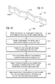
- FIG. 7 illustrates an isometric view of a yet another alternate configuration of a friction adjustment control system for a rotary knob in accordance with an exemplary embodiment of the present invention.
- FIG. 8 illustrates an isometric view of a yet another alternate configuration of a friction adjustment control system with an asymmetrical flat spring for a rotary knob in accordance with an exemplary embodiment of the present invention.
- FIG. 9 illustrates an isometric view of an asymmetrical flat spring for use in a friction adjustment control system of a rotary knob in accordance with an exemplary embodiment of the present invention.
- FIG. 10 illustrates an isometric view of a yet another alternate configuration of a friction adjustment control system with a symmetrical flat spring for a rotary knob in accordance with an exemplary embodiment of the present invention.
- FIG. 12 illustrates a flow chart of a method of controlling rotational positions of knobs in a thermal magnetic trip unit of a circuit breaker in accordance with an exemplary embodiment of the present invention.
- a friction adjustment control system configured to continuously control multiple rotational positions of a rotary knob in a trip unit of a circuit breaker by friction, force, and/or pressure.
- a friction adjustment control system may control infinite rotational positions of thermal and magnetic rotary knobs in a Thermal Magnetic Trip Unit (TMTU) continuously by friction, force, and/or pressure in a Molded Case Circuit Breaker (MCCB).
- TMTU Thermal Magnetic Trip Unit
- MCCB Molded Case Circuit Breaker
- FIG. 1 represents an isometric view of a circuit breaker 10 .
- the circuit breaker include Molded Case Circuit Breakers (MCCBs) with current ratings from 3 A to 2000 A and interrupt ratings up to 200 kA at 480V.
- MCCBs Molded Case Circuit Breakers
- the circuit breaker 10 may be configured in different frame sizes such as from 125 A to 2000 A.
- the circuit breaker 10 is for use in individual enclosures, switchboards, panelboards, and load centers.
- the circuit breaker 10 may include a Thermal Magnetic Trip Unit (TMTU).
- the Thermal Magnetic Trip Unit (TMTU) may provide complete overload and short circuit protection by use of a time delay thermal trip element and an instantaneous magnetic trip element.
- the circuit breaker 10 may include a molded case switch having a factory-installed preset instantaneous function to allow the switch to trip at a value over 1000 A and protect itself against high fault conditions. Overload and fault current protection may be provided by separate over-current devices.
- an operating handle In the circuit breaker 10 being a 4-pole circuit breaker, with the mechanism latched and the contacts open, an operating handle will be in the OFF position. Moving the operating handle to the ON position closes the contacts and establishes a circuit through the circuit breaker 10 . Under overload or short circuit conditions sufficient to automatically trip or open the circuit breaker 10 , the operating handle moves to a position between ON and OFF. To relatch the circuit breaker 10 after automatic operation, the operating handle can be moved to the RESET position. The circuit breaker 10 becomes ready for reclosing. An overcenter toggle mechanism may be trip free of the operating handle. The circuit breaker 10 , therefore, cannot be held closed by means of the operating handle should a tripping condition exist. After automatic operation, the operating handle assumes an intermediate position between ON and OFF, thus displaying a clear indication of tripping.
- the “circuit breaker” refers to a single or multi-pole circuit breaker, as described herein, which corresponds to an automatically operated electrical switch designed to protect an electrical circuit from damage caused by overload or short circuit. Its basic function is to detect a fault condition and interrupt current flow.
- the “multi-pole circuit breaker,” may be used to protect an individual household appliance up to a large switchgear designed to protect high voltage circuits feeding an entire city, and operated by a controller. It should be appreciated that several other components may be included in the “multi-pole circuit breaker.”
- the “multi-pole circuit breaker,” may be capable of operating based on its features such as voltage class, construction type, interrupting type, and structural features.
- the techniques described herein can be particularly useful for controlling rotational positions of rotary knobs in a Thermal Magnetic Trip Unit (TMTU) of a Molded Case Circuit Breaker (MCCB). While particular embodiments are described in terms of thermal and magnetic rotary knobs, the techniques described herein are not limited to thermal and magnetic rotary knobs but can also use knobs with other engagement modes, such as sliding knobs.
- TMTU Thermal Magnetic Trip Unit
- MCCB Molded Case Circuit Breaker
- FIG. 2 it illustrates an isometric view of a trip unit 200 of the circuit breaker 10 including an internal support 205 in accordance with an exemplary embodiment of the present invention.
- the internal support 205 includes a first opening 210 a to receive a first rotary knob 215 a having one or more first smooth rings 220 a and a second opening 210 b to receive a second rotary knob 215 b having one or more second smooth rings 220 b .
- the first opening 210 a of the internal support 205 is configured to slidingly receive the first rotary knob 215 a into position through the first opening 210 a .
- the second opening 210 b of the internal support 205 is configured to slidingly receive the second rotary knob 215 b into position through the second opening 210 b
- the trip unit housings have been usually designed as two halves (two structural parts) split right through the centre of rotation of the knobs. These two halves, knobs and flat step operation springs are put together as a blind assembly.
- the first opening 210 a and the second opening 210 b do not require tight tolerances which are otherwise necessary to make a two halve assembly possible. Absent the tight tolerances, the assemblies are relatively made cheaper.
- the installation process of the first rotary knob 215 a and the second rotary knob 215 b in the trip unit 200 also becomes easier. Therefore, maintenance of the trip unit 200 becomes efficient and less cumbersome as compared to two halves design.
- the first rotary knob 215 a and the second rotary knob 215 b are configured to provide a mechanical control of a corresponding parameter.
- the first rotary knob 215 a provides a control over a thermal parameter in the trip unit 200 .
- the second rotary knob 215 b provides a control over a magnetic parameter in the trip unit 200 .
- This control is enabled by providing continuous infinite rotational positions of the first rotary knob 215 a and the second rotary knob 215 b . These rotational positions may be controlled by friction, force, and/or pressure.
- the function of the thermal and magnetic knobs in the trip unit 200 is to change the settings or ‘Tripping’ behavior of the trip unit 200 .
- the first rotary knob 215 a e.g. thermal knob
- the second rotary knob 215 b e.g., magnetic knob
- the instantaneous settings which protect from higher level short circuit conditions, current levels typically above 5 ⁇ rating of the circuit breaker 10 .
- the first rotary knob 215 a has a top surface 225 a having a groove 230 a and the second rotary knob 215 b has a top surface 225 b having a groove 230 b .
- Both the grooves 230 a , 230 b are shaped to be used with a tool such a flat screw driver to rotate the respective first rotary knob 215 a and the second rotary knob 215 b .
- the first rotary knob 215 a has a head 235 a projecting away from the internal support 205 and the second rotary knob 215 b has a head 235 b projecting away from the internal support 205 .
- the groove 230 a is situated at the distal end of the head 235 a .
- the groove 230 b is situated at the distal end of the head 235 b.
- the first rotary knob 215 a has an axis of rotation 240 a perpendicular to a longitudinal axis 245 of the internal support 205 and the second rotary knob 215 b has an axis of rotation 240 b perpendicular to the longitudinal axis 245 of the internal support 205 .
- Both the first rotary knob 215 a and the second rotary knob 215 b are aligned in a straight line on the longitudinal axis 245 of the internal support 205 and separated by a longitudinal distance 250 .
- Both the first rotary knob 215 a and the second rotary knob 215 b are aligned to operate on a same plane 255 .
- the first rotary knob 215 a is a thermal knob of a molded case circuit breaker (MCCB)
- the second rotary knob 215 b is a magnetic knob of the molded case circuit breaker (MCCB)
- the trip unit 200 is a thermal magnetic trip unit of the molded case circuit breaker (MCCB).
- the internal support 205 , the first rotary knob 215 a , the second rotary knob 215 b may be made of hard plastic via an injection molding process.
- the function and use of such equipment for injection molding circuit breaker parts are well known in the art and are not discussed further.
- FIG. 3 it illustrates an isometric view of a back side view of a knob control system 300 in accordance with an exemplary embodiment of the present invention.
- the knob control system 300 includes a first housing 305 and a first spring 310 installed in the first housing 305 .
- the first housing 305 is configured to press directly against the one or more first smooth rings 220 a of the first rotary knob 215 a.
- Examples of the first spring 310 include a coiled spring.
- the coiled spring may be made of music wire, zinc plated music wire or a stainless steel.
- the coiled spring wire diameter may range from 0.6 mm to over 1.0 mm.
- the coiled spring force may range from 15N to over 50N.
- FIG. 4 illustrates an isometric view of a front side view of the knob control system 300 of FIG. 3 in accordance with an exemplary embodiment of the present invention.
- the first spring 310 may include a flat surface 400 at the end of a coil of the first spring 310 .
- FIG. 5 it illustrates an isometric view of a friction adjustment control system 500 with a coiled spring 505 for a magnetic rotary knob 510 in accordance with an exemplary embodiment of the present invention.
- the friction adjustment control system 500 includes a first knob control 515 of the magnetic rotary knob 510 .
- the first knob control 515 includes a first structural support 520 , a first housing 525 and the coiled spring 505 installed in the first housing 525 against the first structural support 520 to apply a force onto the first housing 525 such that the first housing 525 presses directly against the one or more first smooth rings 220 a of the magnetic rotary knob 510 .
- the first structural support 520 is a part of the internal support 205 .
- the one or more first smooth rings 220 a has a shaped surface that provides control over a plurality of rotational positions of the magnetic rotary knob 510 continuously by friction, force, and/or pressure adjustment.
- FIG. 6 it illustrates an isometric view of a friction adjustment control system 600 with a coiled spring 605 for a thermal rotary knob 610 in accordance with an exemplary embodiment of the present invention.
- the friction adjustment control system 600 includes a second knob control 615 of the thermal rotary knob 610 .
- the second knob control 615 includes a second structural support 620 , a second housing 625 and the coiled spring 605 installed in the second housing 625 against the second structural support 620 to apply a force onto the second housing 625 such that the second housing 625 presses directly against the one or more second smooth rings 220 b of the thermal rotary knob 610 .
- the one or more second smooth rings 220 b has a shaped surface that provides control over a plurality of rotational positions of the thermal rotary knob 610 continuously by friction, force, and/or pressure adjustment.
- FIG. 7 an isometric view of a yet another alternate configuration of a friction adjustment control system 700 for a first rotary knob 705 is depicted in accordance with an exemplary embodiment of the present invention.
- a trip unit includes an internal support 710 having a first pair of slots 715 a , 715 b .
- the friction adjustment control system 700 includes a first knob control 720 of the first rotary knob 705 .
- the first knob control 720 includes a first spring 725 installed in the first pair of slots 715 a , 715 b to apply a force directly against one or more first smooth rings 730 a of the first rotary knob 705 .
- the first spring 725 may be an asymmetrical flat spring with a smooth perimeter.
- the one or more first smooth rings 730 a have a shaped surface that provides control over a plurality of rotational positions of the first rotary knob 705 continuously by friction, force, and/or pressure adjustment.
- the first rotary knob 705 may be a magnetic knob of a molded case circuit breaker (MCCB).
- the trip unit may be a thermal magnetic trip unit of a molded case circuit breaker (MCCB).
- a first opening 735 of the internal support 710 is configured to slidingly receive the first rotary knob 705 into position through the first opening 735 .
- the first spring 725 is a flat spring configured for continuous operation.
- FIG. 8 it also illustrates an isometric view of a yet another alternate configuration of a friction adjustment control system 800 with an asymmetrical flat spring for a second rotary knob 805 in accordance with an exemplary embodiment of the present invention.
- a trip unit includes an internal support 810 having a second pair of slots 815 a , 815 b .
- the friction adjustment control system 800 includes a second knob control 820 of the second rotary knob 805 .
- the second rotary knob 805 includes a second spring 825 , e.g., the asymmetrical flat spring installed in the second pair of slots 815 a , 815 b to apply a force directly against one or more second smooth rings 830 a of the second rotary knob 805 .
- the second spring 825 may be an asymmetrical flat spring with a smooth perimeter.
- the one or more second smooth rings 830 a have a shaped surface that provides control over a plurality of rotational positions of the second rotary knob 805 continuously by friction, force, and/or pressure adjustment.
- the second rotary knob 805 may be a thermal knob of a molded case circuit breaker (MCCB).
- the trip unit may be a thermal magnetic trip unit of a molded case circuit breaker (MCCB)
- a second opening 835 of the internal support 810 is configured to slidingly receive the second rotary knob 805 into position through the second opening 835 .
- the second spring 825 is a flat spring configured for continuous operation.
- FIG. 9 it illustrates an isometric view of an asymmetrical flat spring 900 for use in a friction adjustment control system of a rotary knob in accordance with an exemplary embodiment of the present invention.
- the asymmetrical flat spring 900 having two sides or halves that don't match at least because they are not the same in shape, size, and/or arrangement.
- the asymmetrical flat spring 900 has a first leaf end 905 a and a second leaf end 905 b such that the length of the second leaf end 905 b is larger than the length of the first leaf end 905 a .
- the second leaf end 905 b has a different shape than the first leaf end 905 a as they don't mirror each other physically.
- the first pair of slots 715 a , 715 b and the second pair of slots 815 a , 815 b are configured such that they receive the first leaf end 905 a and the second leaf end 905 b completely within the slot opening.
- the first leaf end 905 a and the second leaf end 905 b are curved in a shape such that the first pair of slots 715 a , 715 b or the second pair of slots 815 a , 815 b holds the asymmetrical flat spring 900 in position frictionally.
- the asymmetrical flat spring 900 having a central portion 910 curved to form a tip 915 that frictionally engages with the one or more first smooth rings 730 a or the one or more second smooth rings 830 a to directly apply a spring force onto the first rotary knob 705 or the second rotary knob 805 , respectively.
- FIG. 10 illustrates an isometric view of a yet another alternate configuration of a friction adjustment control system 1000 with a symmetrical flat spring for a rotary knob 1010 .
- a trip unit includes an internal support 1012 having a pair of slots 1015 a , 1015 b .
- the friction adjustment control system 1000 includes a knob control 1020 of the rotary knob 1010 .
- the knob control 1020 includes a spring 1025 installed in the pair of slots 1015 a , 1015 b to apply a force directly against one or more smooth rings 1030 of the rotary knob 1010 .
- the spring 1025 may be a symmetrical flat spring with a smooth perimeter.
- the one or more smooth rings 1030 have a shaped surface that provides control over a plurality of rotational positions of the rotary knob 1010 continuously by friction, force, and/or pressure adjustment.
- the rotary knob 1010 may be a thermal knob or a magnetic knob of a molded case circuit breaker (MCCB).
- the trip unit may be a thermal magnetic trip unit of a molded case circuit breaker (MCCB)
- An opening 1035 of the internal support 1012 is configured to slidingly receive the rotary knob 1010 into position through the opening 1035 .
- the spring 1025 is a flat spring configured for continuous operation.
- FIG. 11 illustrates an isometric view of a symmetrical flat spring 1100 for use in a friction adjustment control system of a rotary knob in accordance with an exemplary embodiment of the present invention.
- the symmetrical flat spring 1100 having two sides or halves that match at least because they are the same in shape, size, and/or arrangement.
- the symmetrical flat spring 1100 has a first leaf end 1105 a and a second leaf end 1105 b such that the length of the second leaf end 1105 b is same as the length of the first leaf end 1105 a .
- the second leaf end 1105 b has an identical shape as the first leaf end 1105 a since they mirror each other physically.
- the symmetrical flat spring 1100 having a central portion 1110 curved to form a tip 1115 that frictionally engages with the one or more smooth rings 1030 to directly apply a spring force onto the rotary knob 1010 .
- Examples of a flat spring include the symmetrical flat spring 1100 .
- the symmetrical flat spring 1100 may be made of music wire, zinc plated music wire or a stainless steel.
- the symmetrical flat spring 1100 thickness may range from 0.5 mm to over 0.8 mm.
- the symmetrical flat spring 1100 width may range from 1.5 mm to over 4 mm.
- the symmetrical flat spring 1100 force may range from 15N to over 50N.
- the method 1200 further includes in step 1225 applying a first force onto the first housing such that the first housing pushes directly against the one or more first smooth rings of the first rotary knob to provide control over a plurality of rotational positions of the first rotary knob by friction, force, and/or pressure adjustment.
- the method 1200 includes in step 1230 applying a second force onto the second housing such that the second housing pushes directly against the one or more second smooth rings of the second rotary knob to provide control over a plurality of rotational positions of the second rotary knob by friction, force, and/or pressure adjustment.
Landscapes
- Physics & Mathematics (AREA)
- Electromagnetism (AREA)
- Breakers (AREA)
- Adjustable Resistors (AREA)
Abstract
Description
Claims (20)
Priority Applications (2)
| Application Number | Priority Date | Filing Date | Title |
|---|---|---|---|
| US15/040,343 US9627160B1 (en) | 2016-02-10 | 2016-02-10 | Systems and methods for rotary knob friction adjustment control |
| CN201710071269.2A CN107068507B (en) | 2016-02-10 | 2017-02-09 | System and method for knob friction adjustment control |
Applications Claiming Priority (1)
| Application Number | Priority Date | Filing Date | Title |
|---|---|---|---|
| US15/040,343 US9627160B1 (en) | 2016-02-10 | 2016-02-10 | Systems and methods for rotary knob friction adjustment control |
Publications (1)
| Publication Number | Publication Date |
|---|---|
| US9627160B1 true US9627160B1 (en) | 2017-04-18 |
Family
ID=58765475
Family Applications (1)
| Application Number | Title | Priority Date | Filing Date |
|---|---|---|---|
| US15/040,343 Expired - Fee Related US9627160B1 (en) | 2016-02-10 | 2016-02-10 | Systems and methods for rotary knob friction adjustment control |
Country Status (2)
| Country | Link |
|---|---|
| US (1) | US9627160B1 (en) |
| CN (1) | CN107068507B (en) |
Cited By (1)
| Publication number | Priority date | Publication date | Assignee | Title |
|---|---|---|---|---|
| US12383999B2 (en) | 2021-08-20 | 2025-08-12 | Siemens Aktiengesellschaft | Operating facility for a CNC control system for controlling a machine tool with a rotary controller |
Citations (6)
| Publication number | Priority date | Publication date | Assignee | Title |
|---|---|---|---|---|
| US3831120A (en) * | 1973-11-08 | 1974-08-20 | Gen Electric | Trip unit having improved trip adjustment indicator and circuit breaker incorporating same |
| US4691182A (en) * | 1986-04-30 | 1987-09-01 | Westinghouse Electric Corp. | Circuit breaker with adjustable magnetic trip unit |
| US5831501A (en) * | 1997-04-14 | 1998-11-03 | Eaton Corporation | Adjustable trip unit and circuit breaker incorporating same |
| US6667675B2 (en) * | 2002-05-01 | 2003-12-23 | Eaton Corporation | Adjustable magnetic trip assembly for circuit breaker |
| US6956452B2 (en) * | 2003-09-24 | 2005-10-18 | General Electric Company | Apparatus and method for circuit breaker trip unit adjustment |
| US7592888B2 (en) * | 2006-07-14 | 2009-09-22 | Jason Robert Colsch | Low cost user adjustment, resistance to straying between positions, increased resistance to ESD, and consistent feel |
Family Cites Families (6)
| Publication number | Priority date | Publication date | Assignee | Title |
|---|---|---|---|---|
| US7679478B2 (en) * | 2006-07-13 | 2010-03-16 | Siemens Industry, Inc. | Lighting control module mechanical override |
| CN201773800U (en) * | 2010-02-04 | 2011-03-23 | 上海良信电器股份有限公司 | Solenoid adjustable electromagnetic tripping device |
| KR200466511Y1 (en) * | 2011-09-14 | 2013-04-19 | 엘에스산전 주식회사 | Adjusting dial assembly for molded case circuit breaker |
| CN202633134U (en) * | 2012-04-28 | 2012-12-26 | 延锋伟世通电子科技(上海)有限公司 | Knob assembly |
| CN103079375B (en) * | 2012-12-31 | 2016-12-28 | 浙江绍兴苏泊尔生活电器有限公司 | function conversion device for kitchen appliance |
| CN204927207U (en) * | 2015-04-24 | 2015-12-30 | 施耐德电器工业公司 | Circuit breaker knob mechanism |
-
2016
- 2016-02-10 US US15/040,343 patent/US9627160B1/en not_active Expired - Fee Related
-
2017
- 2017-02-09 CN CN201710071269.2A patent/CN107068507B/en not_active Expired - Fee Related
Patent Citations (6)
| Publication number | Priority date | Publication date | Assignee | Title |
|---|---|---|---|---|
| US3831120A (en) * | 1973-11-08 | 1974-08-20 | Gen Electric | Trip unit having improved trip adjustment indicator and circuit breaker incorporating same |
| US4691182A (en) * | 1986-04-30 | 1987-09-01 | Westinghouse Electric Corp. | Circuit breaker with adjustable magnetic trip unit |
| US5831501A (en) * | 1997-04-14 | 1998-11-03 | Eaton Corporation | Adjustable trip unit and circuit breaker incorporating same |
| US6667675B2 (en) * | 2002-05-01 | 2003-12-23 | Eaton Corporation | Adjustable magnetic trip assembly for circuit breaker |
| US6956452B2 (en) * | 2003-09-24 | 2005-10-18 | General Electric Company | Apparatus and method for circuit breaker trip unit adjustment |
| US7592888B2 (en) * | 2006-07-14 | 2009-09-22 | Jason Robert Colsch | Low cost user adjustment, resistance to straying between positions, increased resistance to ESD, and consistent feel |
Cited By (1)
| Publication number | Priority date | Publication date | Assignee | Title |
|---|---|---|---|---|
| US12383999B2 (en) | 2021-08-20 | 2025-08-12 | Siemens Aktiengesellschaft | Operating facility for a CNC control system for controlling a machine tool with a rotary controller |
Also Published As
| Publication number | Publication date |
|---|---|
| CN107068507B (en) | 2020-03-31 |
| CN107068507A (en) | 2017-08-18 |
Similar Documents
| Publication | Publication Date | Title |
|---|---|---|
| US9593863B2 (en) | Vent apparatus for electrical enclosure | |
| JP6225195B2 (en) | Circuit breaker and adapter for circuit breaker | |
| EP3131107B1 (en) | Circuit breaker with movable terminal barrier | |
| US20150243462A1 (en) | Magnetic tripping device and overcurrent tripping device of an electrical switch and electrical switch and method for calibrating the magnetic tripping of a magnetic tripping device | |
| US9812268B2 (en) | Systems and methods for locking a circuit breaker | |
| CN104040674B (en) | circuit breaker for wiring | |
| US9627160B1 (en) | Systems and methods for rotary knob friction adjustment control | |
| CN209859890U (en) | Tripping mechanism of circuit breaker | |
| US6628185B2 (en) | Blade assembly for a circuit breaker | |
| JPH0855555A (en) | Circuit breaker | |
| KR101573605B1 (en) | Trip device of circuit breaker | |
| CA2839286A1 (en) | Moveable contact closing energy transfer system for miniature circuit breakers | |
| KR101829317B1 (en) | Trip apparatus of mold case circuit breaker | |
| KR101463043B1 (en) | Slide-type movable contactor assembly of circuit breaker | |
| KR102081698B1 (en) | Mold case circuit breaker | |
| KR102067391B1 (en) | Mold case circuit breaker | |
| US10763067B1 (en) | Panel wire install indicator of a residential circuit breaker | |
| US9490093B2 (en) | Fuse and trip mechanism therefor | |
| EP3608933B1 (en) | Circuit breaker with snap action contacts | |
| KR200477249Y1 (en) | Instant trip mechanism for small circuit breaker | |
| KR101098227B1 (en) | Wiring breaker with quick reverse mechanism | |
| KR101572753B1 (en) | Trip device of circuit breaker | |
| JP5570023B2 (en) | Circuit breaker | |
| KR200498754Y1 (en) | Adjustable Trip Device of Molded Case Circuit Breaker | |
| KR102067393B1 (en) | Trip apparatus of mold case circuit breaker |
Legal Events
| Date | Code | Title | Description |
|---|---|---|---|
| AS | Assignment |
Owner name: SIEMENS INDUSTRY, INC., GEORGIA Free format text: ASSIGNMENT OF ASSIGNORS INTEREST;ASSIGNORS:ROJKO, JAN;THOMAS, STEPHAN SCOTT;REEL/FRAME:041147/0235 Effective date: 20160329 |
|
| AS | Assignment |
Owner name: SIEMENS AKTIENGESELLSCHAFT, GERMANY Free format text: ASSIGNMENT OF ASSIGNORS INTEREST;ASSIGNOR:SIEMENS INDUSTRY, INC.;REEL/FRAME:041318/0095 Effective date: 20160912 |
|
| STCF | Information on status: patent grant |
Free format text: PATENTED CASE |
|
| MAFP | Maintenance fee payment |
Free format text: PAYMENT OF MAINTENANCE FEE, 4TH YEAR, LARGE ENTITY (ORIGINAL EVENT CODE: M1551); ENTITY STATUS OF PATENT OWNER: LARGE ENTITY Year of fee payment: 4 |
|
| FEPP | Fee payment procedure |
Free format text: MAINTENANCE FEE REMINDER MAILED (ORIGINAL EVENT CODE: REM.); ENTITY STATUS OF PATENT OWNER: LARGE ENTITY |
|
| LAPS | Lapse for failure to pay maintenance fees |
Free format text: PATENT EXPIRED FOR FAILURE TO PAY MAINTENANCE FEES (ORIGINAL EVENT CODE: EXP.); ENTITY STATUS OF PATENT OWNER: LARGE ENTITY |
|
| STCH | Information on status: patent discontinuation |
Free format text: PATENT EXPIRED DUE TO NONPAYMENT OF MAINTENANCE FEES UNDER 37 CFR 1.362 |
|
| FP | Lapsed due to failure to pay maintenance fee |
Effective date: 20250418 |