US9626917B2 - Image display apparatus, driving method of image display apparatus, signal generation apparatus, signal generation program, and signal generation method - Google Patents
Image display apparatus, driving method of image display apparatus, signal generation apparatus, signal generation program, and signal generation method Download PDFInfo
- Publication number
- US9626917B2 US9626917B2 US14/423,822 US201314423822A US9626917B2 US 9626917 B2 US9626917 B2 US 9626917B2 US 201314423822 A US201314423822 A US 201314423822A US 9626917 B2 US9626917 B2 US 9626917B2
- Authority
- US
- United States
- Prior art keywords
- pixel
- signal
- color sub
- value
- minrgb
- Prior art date
- Legal status (The legal status is an assumption and is not a legal conclusion. Google has not performed a legal analysis and makes no representation as to the accuracy of the status listed.)
- Expired - Fee Related, expires
Links
Images


Classifications
-
- G—PHYSICS
- G09—EDUCATION; CRYPTOGRAPHY; DISPLAY; ADVERTISING; SEALS
- G09G—ARRANGEMENTS OR CIRCUITS FOR CONTROL OF INDICATING DEVICES USING STATIC MEANS TO PRESENT VARIABLE INFORMATION
- G09G3/00—Control arrangements or circuits, of interest only in connection with visual indicators other than cathode-ray tubes
- G09G3/20—Control arrangements or circuits, of interest only in connection with visual indicators other than cathode-ray tubes for presentation of an assembly of a number of characters, e.g. a page, by composing the assembly by combination of individual elements arranged in a matrix no fixed position being assigned to or needed to be assigned to the individual characters or partial characters
- G09G3/34—Control arrangements or circuits, of interest only in connection with visual indicators other than cathode-ray tubes for presentation of an assembly of a number of characters, e.g. a page, by composing the assembly by combination of individual elements arranged in a matrix no fixed position being assigned to or needed to be assigned to the individual characters or partial characters by control of light from an independent source
- G09G3/36—Control arrangements or circuits, of interest only in connection with visual indicators other than cathode-ray tubes for presentation of an assembly of a number of characters, e.g. a page, by composing the assembly by combination of individual elements arranged in a matrix no fixed position being assigned to or needed to be assigned to the individual characters or partial characters by control of light from an independent source using liquid crystals
- G09G3/3607—Control arrangements or circuits, of interest only in connection with visual indicators other than cathode-ray tubes for presentation of an assembly of a number of characters, e.g. a page, by composing the assembly by combination of individual elements arranged in a matrix no fixed position being assigned to or needed to be assigned to the individual characters or partial characters by control of light from an independent source using liquid crystals for displaying colours or for displaying grey scales with a specific pixel layout, e.g. using sub-pixels
-
- G—PHYSICS
- G09—EDUCATION; CRYPTOGRAPHY; DISPLAY; ADVERTISING; SEALS
- G09G—ARRANGEMENTS OR CIRCUITS FOR CONTROL OF INDICATING DEVICES USING STATIC MEANS TO PRESENT VARIABLE INFORMATION
- G09G3/00—Control arrangements or circuits, of interest only in connection with visual indicators other than cathode-ray tubes
- G09G3/20—Control arrangements or circuits, of interest only in connection with visual indicators other than cathode-ray tubes for presentation of an assembly of a number of characters, e.g. a page, by composing the assembly by combination of individual elements arranged in a matrix no fixed position being assigned to or needed to be assigned to the individual characters or partial characters
- G09G3/34—Control arrangements or circuits, of interest only in connection with visual indicators other than cathode-ray tubes for presentation of an assembly of a number of characters, e.g. a page, by composing the assembly by combination of individual elements arranged in a matrix no fixed position being assigned to or needed to be assigned to the individual characters or partial characters by control of light from an independent source
- G09G3/3406—Control of illumination source
- G09G3/3413—Details of control of colour illumination sources
-
- G—PHYSICS
- G09—EDUCATION; CRYPTOGRAPHY; DISPLAY; ADVERTISING; SEALS
- G09G—ARRANGEMENTS OR CIRCUITS FOR CONTROL OF INDICATING DEVICES USING STATIC MEANS TO PRESENT VARIABLE INFORMATION
- G09G2300/00—Aspects of the constitution of display devices
- G09G2300/04—Structural and physical details of display devices
- G09G2300/0439—Pixel structures
- G09G2300/0452—Details of colour pixel setup, e.g. pixel composed of a red, a blue and two green components
-
- G—PHYSICS
- G09—EDUCATION; CRYPTOGRAPHY; DISPLAY; ADVERTISING; SEALS
- G09G—ARRANGEMENTS OR CIRCUITS FOR CONTROL OF INDICATING DEVICES USING STATIC MEANS TO PRESENT VARIABLE INFORMATION
- G09G2310/00—Command of the display device
- G09G2310/02—Addressing, scanning or driving the display screen or processing steps related thereto
- G09G2310/0264—Details of driving circuits
- G09G2310/027—Details of drivers for data electrodes, the drivers handling digital grey scale data, e.g. use of D/A converters
-
- G—PHYSICS
- G09—EDUCATION; CRYPTOGRAPHY; DISPLAY; ADVERTISING; SEALS
- G09G—ARRANGEMENTS OR CIRCUITS FOR CONTROL OF INDICATING DEVICES USING STATIC MEANS TO PRESENT VARIABLE INFORMATION
- G09G2320/00—Control of display operating conditions
- G09G2320/02—Improving the quality of display appearance
- G09G2320/0233—Improving the luminance or brightness uniformity across the screen
-
- G—PHYSICS
- G09—EDUCATION; CRYPTOGRAPHY; DISPLAY; ADVERTISING; SEALS
- G09G—ARRANGEMENTS OR CIRCUITS FOR CONTROL OF INDICATING DEVICES USING STATIC MEANS TO PRESENT VARIABLE INFORMATION
- G09G2320/00—Control of display operating conditions
- G09G2320/06—Adjustment of display parameters
- G09G2320/0626—Adjustment of display parameters for control of overall brightness
-
- G—PHYSICS
- G09—EDUCATION; CRYPTOGRAPHY; DISPLAY; ADVERTISING; SEALS
- G09G—ARRANGEMENTS OR CIRCUITS FOR CONTROL OF INDICATING DEVICES USING STATIC MEANS TO PRESENT VARIABLE INFORMATION
- G09G2320/00—Control of display operating conditions
- G09G2320/06—Adjustment of display parameters
- G09G2320/0666—Adjustment of display parameters for control of colour parameters, e.g. colour temperature
-
- G—PHYSICS
- G09—EDUCATION; CRYPTOGRAPHY; DISPLAY; ADVERTISING; SEALS
- G09G—ARRANGEMENTS OR CIRCUITS FOR CONTROL OF INDICATING DEVICES USING STATIC MEANS TO PRESENT VARIABLE INFORMATION
- G09G2340/00—Aspects of display data processing
- G09G2340/06—Colour space transformation
-
- G—PHYSICS
- G09—EDUCATION; CRYPTOGRAPHY; DISPLAY; ADVERTISING; SEALS
- G09G—ARRANGEMENTS OR CIRCUITS FOR CONTROL OF INDICATING DEVICES USING STATIC MEANS TO PRESENT VARIABLE INFORMATION
- G09G2360/00—Aspects of the architecture of display systems
- G09G2360/16—Calculation or use of calculated indices related to luminance levels in display data
Definitions
- the present disclosure relates to an image display apparatus, a driving method of the image display apparatus, a signal generation apparatus, a signal generation program, and a signal generation method
- a technique attracts attention, which has a configuration including not only three sub-pixels, i.e., a red color sub-pixel displaying red color, a green color sub-pixel displaying green color, and a blue color sub-pixel displaying blue color, but also, for example, a white color sub-pixel displaying white color.
- Patent Document 1 Publication of Japanese Patent No. 4120674 (Patent Document 1) describes an image display apparatus including a liquid crystal panel provided with a display pixel including not only a sub-pixel for color display but also a sub-pixel having a transparent or white color area, an illumination apparatus for illuminating the liquid crystal panel, and an display image conversion circuit for determining an image signal corresponding to a sub-pixel on the basis of an input RGB image signal and a control signal for adjusting the luminance of light emitted from the illumination apparatus.
- Patent Document 1 JP 4120674 B2
- Cited Document 1 the luminance of the light emitted from the illumination apparatus is considered to be controllable, and based on the assumption, the image signal corresponding to each sub-pixel is determined on the basis of the input RGB image signal. Therefore, this technique is not suitable for controlling, e.g., a reflection-type image display apparatus for displaying by using reflection of outside light and an image display apparatus having an illumination apparatus having such configuration that the intensity of the output light is fixed.
- an image display apparatus a driving method of an image display apparatus, a signal generation apparatus, a signal generation program, and a signal generation method capable of reliably increasing the luminance even if, e.g., display is performed by reflecting outside light.
- An image display apparatus for achieving the above purpose includes:
- an image display unit in which pixels constituted by a red color sub-pixel, a green color sub-pixel, a blue color sub-pixel, and a white color sub-pixel are arranged in a two-dimensional matrix manner;
- a signal generation unit which generates a signal for the red color sub-pixel, a signal for the green color sub-pixel, a signal for the blue color sub-pixel, and a signal for the white color sub-pixel on the basis of an image signal for red color display, an image signal for green color display, and an image signal for blue color display which are provided according to an image to be displayed,
- the image signal for red color display, the image signal for green color display, and the image signal for blue color display which are linearized and normalized and which correspond to a pixel are denoted as reference symbol R nL , reference symbol G nL , reference symbol B nL , respectively, a minimum value thereof is denoted as MinRGB nL , and a threshold defined as a predetermined value is denoted as reference symbol TH 1 (however, 0 ⁇ TH 1 ⁇ 1),
- the signal generation unit generates a signal for each sub-pixel such that:
- the value of the signal for the white color sub-pixel is MinRGB nL /TH 1 ,
- the value of the signal for the red color sub-pixel is R nL ⁇ MinRGB nL ,
- the value of the signal for the green color sub-pixel is G nL ⁇ MinRGB nL , and
- the value of the signal for the blue color sub-pixel is B nL ⁇ MinRGB nL , and
- the signal generation unit generates a signal for each sub-pixel such that:
- the value of the signal for the white color sub-pixel is 1,
- the value of the signal for the red color sub-pixel is (R nL ⁇ TH 1 )/(1 ⁇ TH 1 ),
- the value of the signal for the green color sub-pixel is (G nL ⁇ TH 1 )/(1 ⁇ TH 1 ), and
- the value of the signal for the blue color sub-pixel is (B nL ⁇ TH 1 )/(1 ⁇ TH 1 ).
- a driving method of an image display apparatus for achieving the above purpose includes an image display unit in which pixels constituted by a red color sub-pixel, a green color sub-pixel, a blue color sub-pixel, and a white color sub-pixel are arranged in a two-dimensional matrix manner, and a signal generation unit which generates a signal for the red color sub-pixel, a signal for the green color sub-pixel, a signal for the blue color sub-pixel, and a signal for the white color sub-pixel on the basis of an image signal for red color display, an image signal for green color display, and an image signal for blue color display which are provided according to an image to be displayed,
- the image signal for red color display, the image signal for green color display, and the image signal for blue color display which are linearized and normalized and which correspond to a pixel are denoted as reference symbol R nL , reference symbol G nL , reference symbol B nL , respectively, a minimum value thereof is denoted as MinRGB nL , and a threshold defined as a predetermined value is denoted as reference symbol TH 1 (however, 0 ⁇ TH 1 ⁇ 1),
- the signal generation unit generates a signal for each sub-pixel such that:
- the value of the signal for the white color sub-pixel is MinRGB nL /TH 1 ,
- the value of the signal for the red color sub-pixel is R nL ⁇ MinRGB nL ,
- the value of the signal for the green color sub-pixel is G nL ⁇ MinRGB nL , and
- the value of the signal for the blue color sub-pixel is B nL ⁇ MinRGB nL , and
- the signal generation unit generates a signal for each sub-pixel such that:
- the value of the signal for the white color sub-pixel is 1,
- the value of the signal for the red color sub-pixel is (R nL ⁇ TH 1 )/(1 ⁇ TH 1 ),
- the value of the signal for the green color sub-pixel is (G nL ⁇ TH 1 )/(1 ⁇ TH 1 ), and
- the value of the signal for the blue color sub-pixel is (B nL ⁇ TH 1 )/(1 ⁇ TH 1 ).
- a signal generation program for achieving the above purpose is executed by a signal generation apparatus which generates a signal for a red color sub-pixel, a signal for a green color sub-pixel, a signal for a blue color sub-pixel, and a signal for the white color sub-pixel on the basis of an image signal for red color display, an image signal for green color display, and an image signal for blue color display which are provided according to an image to be displayed,
- the image signal for red color display, the image signal for green color display, and the image signal for blue color display which are linearized and normalized and which correspond to a pixel are denoted as reference symbol R nL , reference symbol G nL , reference symbol B nL , respectively, a minimum value thereof is denoted as MinRGB nL , and a threshold defined as a predetermined value is denoted as reference symbol TH 1 (however, 0 ⁇ TH 1 ⁇ 1),
- the signal generation apparatus generates a signal for each sub-pixel such that:
- the value of the signal for the white color sub-pixel is MinRGB nL /TH 1 ,
- the value of the signal for the red color sub-pixel is R nL ⁇ MinRGB nL ,
- the value of the signal for the green color sub-pixel is G nL ⁇ MinRGB nL , and
- the value of the signal for the blue color sub-pixel is B nL ⁇ MinRGB nL , and
- the signal generation apparatus generates a signal for each sub-pixel such that:
- the value of the signal for the white color sub-pixel is 1,
- the value of the signal for the red color sub-pixel is (R nL ⁇ TH 1 )/(1 ⁇ TH 1 ),
- the value of the signal for the green color sub-pixel is (G nL ⁇ TH 1 )/(1 ⁇ TH 1 ), and
- the value of the signal for the blue color sub-pixel is (B nL ⁇ TH 1 )/(1 ⁇ TH 1 ).
- a signal generation apparatus for achieving the above purpose generates a signal for a red color sub-pixel, a signal for a green color sub-pixel, a signal for a blue color sub-pixel, and a signal for a white color sub-pixel on the basis of an image signal for red color display, an image signal for green color display, and an image signal for blue color display which are provided according to an image to be displayed,
- the image signal for red color display, the image signal for green color display, and the image signal for blue color display which are linearized and normalized and which correspond to a pixel are denoted as reference symbol R nL , reference symbol G nL , reference symbol B nL , respectively, a minimum value thereof is denoted as MinRGB nL , and a threshold defined as a predetermined value is denoted as reference symbol TH 1 (however, 0 ⁇ TH 1 ⁇ 1),
- the signal generation apparatus generates a signal for each sub-pixel such that:
- the value of the signal for the white color sub-pixel is MinRGB nL /TH 1 ,
- the value of the signal for the red color sub-pixel is R nL ⁇ MinRGB nL ,
- the value of the signal for the green color sub-pixel is G nL ⁇ MinRGB nL , and
- the value of the signal for the blue color sub-pixel is B nL ⁇ MinRGB nL , and
- the signal generation apparatus generates a signal for each sub-pixel such that:
- the value of the signal for the white color sub-pixel is 1,
- the value of the signal for the red color sub-pixel is (R nL ⁇ TH 1 )/(1 ⁇ TH 1 ),
- the value of the signal for the green color sub-pixel is (G nL ⁇ TH 1 )/(1 ⁇ TH 1 ), and
- the value of the signal for the blue color sub-pixel is (B nL ⁇ TH 1 )/(1 ⁇ TH 1 ).
- a signal generation method for achieving the above purpose includes generating a signal for the red color sub-pixel, a signal for the green color sub-pixel, a signal for the blue color sub-pixel, and a signal for the white color sub-pixel on the basis of an image signal for red color display, an image signal for green color display, and an image signal for blue color display which are provided according to an image to be displayed, wherein the image signal for red color display, the image signal for green color display, and the image signal for blue color display which are linearized and normalized and which correspond to a pixel are denoted as reference symbol R nL , reference symbol G nL , reference symbol B nL , respectively, a minimum value thereof is denoted as MinRGB nL , and a threshold defined as a predetermined value is denoted as reference symbol TH 1 (however, 0 ⁇ TH 1 ⁇ 1),
- the value of the signal for the white color sub-pixel is MinRGB nL /TH 1 ,
- the value of the signal for the red color sub-pixel is R nL ⁇ MinRGB nL ,
- the value of the signal for the green color sub-pixel is G nL ⁇ MinRGB nL , and
- the value of the signal for the blue color sub-pixel is B nL ⁇ MinRGB nL , and
- the value of the signal for the white color sub-pixel is 1,
- the value of the signal for the red color sub-pixel is (R nL ⁇ TH 1 )/(1 ⁇ TH 1 ),
- the value of the signal for the green color sub-pixel is (G nL ⁇ TH 1 )/(1 ⁇ TH 1 ), and
- the value of the signal for the blue color sub-pixel is (B nL ⁇ TH 1 )/(1 ⁇ TH 1 ).
- an image is displayed by effectively using a white color sub-pixel. Therefore, the luminance of the image displayed can be reliably increased.
- FIG. 1 is a schematic view illustrating an image display apparatus according to a first embodiment.
- FIG. 2 is a schematic top view for explaining brightness in a case, where white color is displayed with the maximum luminance in design when assuming a pixel is constituted by three sub-pixels including a red color sub-pixel, a green color sub-pixel, and a blue color sub-pixel.
- FIG. 3 is a schematic top view for explaining brightness in a case, where white color is displayed with the maximum luminance in design when a pixel is constituted by four sub-pixels including a red color sub-pixel, a green color sub-pixel, a blue color sub-pixel, and a white color sub-pixel in an image display unit.
- FIG. 4 is a schematic graph for explaining processing in a case, where MinRGB nL ⁇ TH 1 holds.
- FIG. 5 is a schematic graph for explaining processing in a case, where MinRGB nL >TH 1 holds.
- FIG. 6 is a schematic graph for explaining processing in a case, where a video signal displaying white color with the maximum luminance is input.
- an image display unit may be suitable for display of a motion picture, or may be suitable for display of a still picture, or the image display unit may be reflection-type or a transmission-type.
- Well-known display unit materials such as a reflection-type liquid crystal display panel and an electronic paper can be used as a reflection-type image display unit.
- Well-known display unit materials such as a transmission-type liquid crystal display panel can be used as a transmission-type image display unit.
- the transmission-type image display unit includes a semi-transmission-type image display unit which has the features of both of the transmission-type and the reflection-type.
- Examples of pixel values include several image display resolutions such as not only VGA (640, 480), S-VGA (800, 600), XGA (1024, 768), APRC (1152, 900), S-XGA (1280, 1024), U-XGA (1600, 1200), HD-TV (1920, 1080), and Q-XGA (2048, 1536), but also (1920, 1035), (720, 480), and (1280, 960), but the values are not limited thereto.
- a predetermined threshold TH 1 may be set appropriately in accordance with a configuration such as an image display unit.
- a configuration such as an image display unit.
- the maximum luminance of white color display in design that can be displayed by a red color sub-pixel, a green color sub-pixel, and a blue color sub-pixel in a single pixel is denoted as W R+G+B _ max
- the maximum brightness of white color display in design that can be displayed by a white color sub-pixel in a single pixel is denoted as W W _ max
- the value of the threshold TH 1 is configured to be set to a value given by W W _ max /(W R+G+B _ max +W W _ max ), so that the increase of the brightness of the image due to the white color sub-pixel can be best achieved.
- the values of the brightness W R+G+B _ max , W W _ max explained above can be obtained on the basis of the structure of the image display unit, or can be measured by operating the
- a signal generation unit and a signal generation apparatus used in the present disclosure can be constituted from, for example, a calculation circuit and a storage apparatus. They can be constituted by using well-known circuit elements and the like. This is also applicable to a linearization and normalization unit and a non-linearization and quantization unit as shown in FIG. 1 explained later.
- the signal generation unit and the signal generation apparatus may be configured to operate on the basis of physical wiring made by hardware, or may be configured to operate on the basis of a program.
- the first embodiment relates to an image display apparatus a driving method of the image display apparatus, a signal generation apparatus, a signal generation program, and a signal generation method according to the present disclosure.
- the image signal for red color display is denoted as reference symbol R sRGB
- the image signal for green color display is denoted as reference symbol G sRGB
- the image signal for blue color display is denoted as reference symbol B sRGB .
- the image signals R sRGB , G sRGB , B sRGB have values between 0 to 255 in accordance with the luminance of the image to be displayed. In the explanation about this case, a value of [0] indicates the minimum luminance, and a value of [255] indicates the maximum luminance.
- FIG. 1 is a schematic view illustrating an image display apparatus according to the first embodiment.
- the image display apparatus 1 includes an image display unit 40 in which pixels 42 constituted by the red color sub-pixel 42 R , the green color sub-pixel 42 G , the blue color sub-pixel 42 B the and white color sub-pixel 42 W are arranged in a two-dimensional matrix manner, and a signal generation unit (signal generation apparatus) 20 for generating the signal for the red color sub-pixel, the signal for the green color sub-pixel, the signal for the blue color sub-pixel, and the signal for the white color sub-pixel on the basis of an image signal for red color display, an image signal for green color display, and an image signal for blue color display provided according to the image to be displayed.
- a display area having pixels 42 arranged in a two-dimensional matrix manner is denoted by reference symbol 41 .
- the image display apparatus 1 further includes a linearization and normalization unit 10 for making the externally input image signal R sRGB , G sRGB , B sRGB into linearized and normalized image signal, and a non-linearization and quantization unit 30 for making generated signals R cvt , G cvt , B cvt , W cvt into output signals of 8-bit sRGB method.
- a linearization and normalization unit 10 for making the externally input image signal R sRGB , G sRGB , B sRGB into linearized and normalized image signal
- a non-linearization and quantization unit 30 for making generated signals R cvt , G cvt , B cvt , W cvt into output signals of 8-bit sRGB method.
- the image display unit 40 is constituted by, for example, electronic paper or a reflection-type liquid crystal display panel. More specifically, the image display unit 40 is the reflection-type, and displays an image by changing the reflectance of outside light incident upon the image display unit 40 . It should be noted that the image display unit 40 may be configured to be a transmission-type (for example, a combination of a transmission-type liquid crystal display panel and a backlight configured to have fixed strength of output light).
- a transmission-type for example, a combination of a transmission-type liquid crystal display panel and a backlight configured to have fixed strength of output light.
- the red color sub-pixel 42 R has such a structure made by laminating, for example, a color filter transmitting red color and a reflection area where the degree of reflection of light can be controlled. Red color is displayed by controlling the reflectance of the incident outside light.
- the green color sub-pixel 42 G has such structure made by laminating, for example, a color filter transmitting green color and a reflection area.
- the blue color sub-pixel 42 B has such structure made by laminating, for example, a color filter transmitting blue color and a reflection area.
- FIG. 2 is a schematic top view for explaining brightness in a case, where white color is displayed with the maximum luminance in design when assuming a pixel is constituted by three sub-pixels including a red color sub-pixel, a green color sub-pixel, and a blue color sub-pixel.
- the size of area occupied by a single pixel 42 is denoted as reference symbol S PX
- the red color sub-pixel, the green color sub-pixel, and the blue color sub-pixel are denoted as reference symbols 42 R ′, 42 G ′ and 42 B ′, respectively.
- the size of area occupied by each sub-pixel is considered to be approximately S PX /3.
- the red color sub-pixel 42 R ′, green color sub-pixel 42 G ′, blue color sub-pixel 42 B ′ displays white color by using additive color mixture (more specifically, juxtaposition additive color mixture).
- the outside light of white color having a certain strength is incident upon the pixel 42 , and when the red color sub-pixel 42 R ′ attains the maximum luminance in design, approximately half of the red color component of the outside light is reflected, and when the green color sub-pixel 42 G ′ attains the maximum luminance in design, approximately half of the green color component of the outside light is reflected, and when the blue color sub-pixel 42 B ′ attains the maximum luminance in design, approximately half of the green color component of the outside light is reflected.
- This is also applicable the explanation with reference to FIG. 3 described later.
- the maximum luminance in design produced by the white color display made through additive color mixture for adding the red color sub-pixel 42 R ′, the green color sub-pixel 42 G ′, and the blue color sub-pixel 42 B ′ is approximately “1 ⁇ 2”. More specifically, the brightness of the output light is approximately “1 ⁇ 2”.
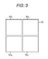
- FIG. 3 is a schematic top view for explaining brightness in a case, where white color is displayed with the maximum luminance in design when a pixel is constituted by four sub-pixels including a red color sub-pixel, a green color sub-pixel, a blue color sub-pixel, and a white color sub-pixel in an image display unit.
- the size of area occupied by the red color sub-pixel 42 R , the green color sub-pixel 42 G , the blue color sub-pixel 42 B and the white color sub-pixel 42 W is approximately S PX /4.
- the size of area occupied by the red color sub-pixel 42 R , the green color sub-pixel 42 G , and the blue color sub-pixel 42 B is 3 ⁇ 4 of the size of area occupied by the red color sub-pixel 42 R ′, the green color sub-pixel 42 G ′, and the blue color sub-pixel 42 B ′ in FIG. 2 . Therefore, the brightness of the white color in the additive color mixture of the red color sub-pixel 42 R , the green color sub-pixel 42 G , and the blue color sub-pixel 42 B (the brightness of the output light) is “1 ⁇ 2” ⁇ “3 ⁇ 4”, which is “3 ⁇ 8”.
- the brightness of the white color of the white color sub-pixel 42 W (the brightness of the output light) is “1 ⁇ 4” because of the size of area occupied by the white color sub-pixel, where the brightness of the outside light incident upon the pixel 42 is “1”.
- the brightness of the pixel in FIG. 3 is “3 ⁇ 8”+“1 ⁇ 4”, which is approximately “5 ⁇ 8”.
- the configuration of FIG. 3 can enhance the luminance of the image more greatly than the configuration of FIG. 2 .
- the signal generation unit (signal generation apparatus) 20 constituting the image display apparatus 1 operates on the basis of a signal generation program stored in storage means, not shown.
- the image signal for red color display, the image signal for green color display, and the image signal for blue color display which are linearized and normalized and correspond to a pixel are denoted as reference symbol R nL , reference symbol G nL , and reference symbol B nL , and where the minimum value thereof is denoted as MinRGB nL , and a threshold defined as a predetermined value is denoted as reference symbol TH 1 (however, 0 ⁇ TH 1 ⁇ 1), the signal generation unit (signal generation apparatus) generates a signal for each sub-pixel such that,
- the value of the signal for the white color sub-pixel is MinRGB nL /TH 1 ,
- the value of the signal for the red color sub-pixel is R nL ⁇ MinRGB nL ,
- the value of the signal for the green color sub-pixel is G nL ⁇ MinRGB nL , and
- the value of the signal for the blue color sub-pixel is B nL ⁇ MinRGB nL , and
- the signal generation unit (signal generation apparatus) 20 generates a signal for each sub-pixel such that,
- the value of the signal for the white color sub-pixel is 1,
- the value of the signal for the red color sub-pixel is (R nL ⁇ TH 1 )/(1 ⁇ TH 1 ),
- the value of the signal for the green color sub-pixel is (G nL ⁇ TH 1 )/(1 ⁇ TH 1 ), and
- the value of the signal for the blue color sub-pixel is (B nL ⁇ TH 1 )/(1 ⁇ TH 1 ).
- the threshold TH 1 explained above is set to a value given by W W _ max /(W R+G+B _ max +W W _ max ).
- the linearization and normalization unit 10 generates a linearized and normalized signal on the basis of the input image signals R sRGB , G sRGB , B sRGB .
- R temp1 ⁇ 0.04045 the following expression is calculated.
- R nL R temp1 /12.92 (2)
- R temp1 >0.04045 holds, the following expression is calculated.
- R nL (( R temp1 +0.055)/1.055 2.4 (3)
- the signal G nL for green color display and the signal B nL for blue color display which are linearized and normalized can be generated on the basis of the similar expression.
- reference symbol R temp1 may be deemed to be replaced with reference symbol G temp1
- reference symbol R nL may be deemed to be replaced with reference symbol G nL in the expressions (1) to (3)
- the signal B nL may also be generated by appropriately replacing the variables.
- the signal generation unit 20 generates a signal for each sub-pixel on the basis of linearized and normalized signals R nL , G nL , B nL and the threshold TH 1 defined as a predetermined value.
- the signal for the red color sub-pixel is denoted as reference symbol R cvt
- the signal for the green color sub-pixel is denoted as reference symbol G cvt
- the signal for the blue color sub-pixel is denoted as reference symbol B cvt
- the signal for the white color sub-pixel is denoted as reference symbol W cvt .
- MinRGB nL The minimum value of the signals R nL , G nL , B nL is denoted as reference symbol MinRGB nL .
- the minimum value MinRGB nL can be expressed as in the following expression (4) using a function min that outputs the minimum value of the argument.
- Min RGB nL min( R nL ,G nL ,B nL ) (4)
- W cvt Min ⁇ ⁇ RGB nL / TH 1 ( 5 )
- the generated signals W cvt , R cvt , G cvt , B cvt are input into the non-linearization and quantization unit 30 , which outputs them as digital signals of the sRGB method.
- the signal for the red color sub-pixel is denoted as reference symbol R out
- the signal for the green color sub-pixel is denoted as reference symbol G out
- the signal for the blue color sub-pixel is denoted as reference symbol B out
- the signal for the white color sub-pixel is denoted as reference symbol W out .
- the signal for the red color sub-pixel R out will be explained.
- the signal R out can be generated on the basis of the following expressions (13) to (15).
- reference symbol R temp2 in the expressions (13) to (15) is a temporary variable for the sake of calculation.
- the function round in the expression (15) is a function for rounding off a numerical value to an integer.
- the signal for the green color sub-pixel G out , the signal for the blue color sub-pixel B out , and the signal for the white color sub-pixel W out can also be generated on the basis of the similar expression.
- reference symbol R temp2 may be deemed to be replaced with reference symbol G temp1
- reference symbol R cvt may be deemed to be replaced with reference symbol G cvt
- reference symbol R out may be deemed to be replaced with reference symbol G out in the expressions (13) to (15).
- the signals B out , W out may also be generated by appropriately replacing the variables.
- the image display unit 40 operates on the basis of the signal for the red color sub-pixel R out , the signal for the green color sub-pixel G out , the signal for the blue color sub-pixel B out , and the signal for the white color sub-pixel W out , and displays an image.
- FIG. 4 is a schematic graph for explaining processing in a case, where MinRGB nL ⁇ TH 1 holds.
- the smallest of the signals R nL , G nL , B nL is the signal B nL ([1] in the drawing).
- FIG. 5 is a schematic graph for explaining processing in a case, where MinRGB nL >TH 1 holds.
- the smallest of the signals R nL , G nL , B nL is the signal B nL ([1] in the drawing).
- FIG. 6 is a schematic graph for explaining processing in a case, where a video signal displaying white color with the maximum luminance is input.
- the signals R nL , G nL , B nL are 1 ([1] in the drawing).
- the signals are generated so that the signal for the red color sub-pixel R cvt , the signal for the green color sub-pixel G cvt , the signal for the blue color sub-pixel B cvt and the signal for the white color sub-pixel W cvt become [1]. Therefore, the white color can be displayed with the maximum luminance of the image display unit 40 in design.
- a reference example may be considered in which the minimum value of the signals R nL , G nL , B nL is adopted as the value of the signal W cvt , and the signals R cvt , G cvt , B cvt are obtained by subtracting the signal W cvt from the signals R nL , G nL , B nL , respectively. More specifically, the processing as shown in the following expressions (15) to (18) will be performed.
- W cvt Min RGB nL (15)
- R cvt R nL ⁇ W cvt (16)
- G cvt G nL ⁇ W cvt (17)
- B cvt B nL ⁇ W cvt (18)
- a reference example may be considered, in which the minimum value of the signals R nL , G nL , B nL is adopted as the value of the signal W cvt , and the signals R nL , G nL , B nL are adopted as the signals R cvt , G cvt , B cvt , respectively, as they are. More specifically, the processing as shown in the following expressions (19) to (22) is performed.
- W cvt Min RGB nL (19)
- R cvt R nL (20)
- G cvt G nL (21)
- B cvt B nL (22)
- the threshold TH 1 not only the threshold TH 1 but also another threshold may be set, and the signal processing may be configured to be switched in accordance with the relationship in the magnitude with MinRGB nL .
- An image display apparatus including:
- an image display unit in which pixels constituted by a red color sub-pixel, a green color sub-pixel, a blue color sub-pixel, and a white color sub-pixel are arranged in a two-dimensional matrix manner;
- a signal generation unit which generates a signal for the red color sub-pixel, a signal for the green color sub-pixel, a signal for the blue color sub-pixel, and a signal for the white color sub-pixel on the basis of an image signal for red color display, an image signal for green color display, and an image signal for blue color display which are provided according to an image to be displayed,
- the image signal for red color display, the image signal for green color display, and the image signal for blue color display which are linearized and normalized and which correspond to a pixel are denoted as reference symbol R nL , reference symbol G nL , reference symbol B nL , respectively, a minimum value thereof is denoted as MinRGB nL , and a threshold defined as a predetermined value is denoted as reference symbol TH 1 (however, 0 ⁇ TH 1 ⁇ 1),
- the signal generation unit generates a signal for each sub-pixel such that:
- the value of the signal for the white color sub-pixel is MinRGB nL /TH 1 ,
- the value of the signal for the red color sub-pixel is R nL ⁇ MinRGB nL ,
- the value of the signal for the green color sub-pixel is G nL ⁇ MinRGB nL , and
- the value of the signal for the blue color sub-pixel is B nL ⁇ MinRGB nL , and
- the signal generation unit generates a signal for each sub-pixel such that:
- the value of the signal for the white color sub-pixel is 1,
- the value of the signal for the red color sub-pixel is (R nL ⁇ TH 1 )/(1 ⁇ TH 1 ),
- the value of the signal for the green color sub-pixel is (G nL ⁇ TH 1 )/(1 ⁇ TH 1 ), and
- the value of the signal for the blue color sub-pixel is (B nL ⁇ TH 1 )/(1 ⁇ TH 1 ).
- the value of the threshold TH 1 is set to a value given by W W _ max /(W R+G+B _ max +W W _ max ).
- a driving method of an image display apparatus including an image display unit in which pixels constituted by a red color sub-pixel, a green color sub-pixel, a blue color sub-pixel, and a white color sub-pixel are arranged in a two-dimensional matrix manner, and a signal generation unit which generates a signal for the red color sub-pixel, a signal for the green color sub-pixel, a signal for the blue color sub-pixel, and a signal for the white color sub-pixel on the basis of an image signal for red color display, an image signal for green color display, and an image signal for blue color display which are provided according to an image to be displayed,
- the image signal for red color display, the image signal for green color display, and the image signal for blue color display which are linearized and normalized and which correspond to a pixel are denoted as reference symbol R nL , reference symbol G nL , reference symbol B nL , respectively, a minimum value thereof is denoted as MinRGB nL , and a threshold defined as a predetermined value is denoted as reference symbol TH 1 (however, 0 ⁇ TH 1 ⁇ 1),
- the signal generation unit generates a signal for each sub-pixel such that:
- the value of the signal for the white color sub-pixel is MinRGB nL /TH 1 ,
- the value of the signal for the red color sub-pixel is R nL ⁇ MinRGB nL ,
- the value of the signal for the green color sub-pixel is G nL ⁇ MinRGB nL , and
- the value of the signal for the blue color sub-pixel is B nL ⁇ MinRGB nL , and
- the signal generation unit generates a signal for each sub-pixel such that:
- the value of the signal for the white color sub-pixel is 1,
- the value of the signal for the red color sub-pixel is (R nL ⁇ TH 1 )/(1 ⁇ TH 1 ),
- the value of the signal for the green color sub-pixel is (G nL ⁇ TH 1 )/(1 ⁇ TH 1 ), and
- the value of the signal for the blue color sub-pixel is (B nL ⁇ TH 1 )/(1 ⁇ TH 1 ).
- a signal generation program executed by a signal generation apparatus which generates a signal for a red color sub-pixel, a signal for a green color sub-pixel, a signal for a blue color sub-pixel, and a signal for the white color sub-pixel on the basis of an image signal for red color display, an image signal for green color display, and an image signal for blue color display which are provided according to an image to be displayed,
- the image signal for red color display, the image signal for green color display, and the image signal for blue color display which are linearized and normalized and which correspond to a pixel are denoted as reference symbol R nL , reference symbol G nL , reference symbol B nL , respectively, a minimum value thereof is denoted as MinRGB nL , and a threshold defined as a predetermined value is denoted as reference symbol TH 1 (however, 0 ⁇ TH 1 ⁇ 1),
- the signal generation apparatus generates a signal for each sub-pixel such that:
- the value of the signal for the white color sub-pixel is MinRGB nL /TH 1 ,
- the value of the signal for the red color sub-pixel is R nL ⁇ MinRGB nL ,
- the value of the signal for the green color sub-pixel is G nL ⁇ MinRGB nL , and
- the value of the signal for the blue color sub-pixel is B nL ⁇ MinRGB nL , and
- the signal generation apparatus generates a signal for each sub-pixel such that:
- the value of the signal for the white color sub-pixel is 1,
- the value of the signal for the red color sub-pixel is (R nL ⁇ TH 1 )/(1 ⁇ TH 1 ),
- the value of the signal for the green color sub-pixel is (G nL ⁇ TH 1 )/(1 ⁇ TH 1 ), and
- the value of the signal for the blue color sub-pixel is (B nL ⁇ TH 1 )/(1 ⁇ TH 1 ).
- a signal generation apparatus which generates a signal for the a color sub-pixel, a signal for a green color sub-pixel, a signal for a blue color sub-pixel, and a signal for a white color sub-pixel on the basis of an image signal for red color display, an image signal for green color display, and an image signal for blue color display which are provided according to an image to be displayed,
- the image signal for red color display, the image signal for green color display, and the image signal for blue color display which are linearized and normalized and which correspond to a pixel are denoted as reference symbol R nL , reference symbol G nL , reference symbol B nL , respectively, a minimum value thereof is denoted as MinRGB nL , and a threshold defined as a predetermined value is denoted as reference symbol TH 1 (however, 0 ⁇ TH 1 ⁇ 1),
- the signal generation apparatus generates a signal for each sub-pixel such that:
- the value of the signal for the white color sub-pixel is MinRGB nL /TH 1 ,
- the value of the signal for the red color sub-pixel is R nL ⁇ MinRGB nL ,
- the value of the signal for the green color sub-pixel is G nL ⁇ MinRGB nL , and
- the value of the signal for the blue color sub-pixel is B nL ⁇ MinRGB nL , and
- the signal generation apparatus generates a signal for each sub-pixel such that:
- the value of the signal for the white color sub-pixel is 1,
- the value of the signal for the red color sub-pixel is (R nL ⁇ TH 1 )/(1 ⁇ TH 1 ),
- the value of the signal for the green color sub-pixel is (G nL ⁇ TH 1 )/(1 ⁇ TH 1 ), and
- the value of the signal for the blue color sub-pixel is (B nL ⁇ TH 1 )/(1 ⁇ TH 1 ).
- the value of the threshold TH 1 is set to a value given by W W _ max /(W R+G+B _ max +W W _ max ).
- a signal generation method which generates a signal for a red color sub-pixel, a signal for a green color sub-pixel, a signal for a blue color sub-pixel, and a signal for a white color sub-pixel on the basis of an image signal for red color display, an image signal for green color display, and an image signal for blue color display which are provided according to an image to be displayed,
- the image signal for red color display, the image signal for green color display, and the image signal for blue color display which are linearized and normalized and which correspond to a pixel are denoted as reference symbol R nL , reference symbol G nL , reference symbol B nL , respectively, a minimum value thereof is denoted as MinRGB nL , and a threshold defined as a predetermined value is denoted as reference symbol TH 1 (however, 0 ⁇ TH 1 ⁇ 1),
- the value of the signal for the white color sub-pixel is MinRGB nL /TH 1 ,
- the value of the signal for the red color sub-pixel is R nL ⁇ MinRGB nL ,
- the value of the signal for the green color sub-pixel is G nL ⁇ MinRGB nL , and
- the value of the signal for the blue color sub-pixel is B nL ⁇ MinRGB nL , and
- the value of the signal for the white color sub-pixel is 1,
- the value of the signal for the red color sub-pixel is (R nL ⁇ TH 1 )/(1 ⁇ TH 1 ),
- the value of the signal for the green color sub-pixel is (G nL ⁇ TH 1 )/(1 ⁇ TH 1 ), and
- the value of the signal for the blue color sub-pixel is (B nL ⁇ TH 1 )/(1 ⁇ TH 1 ).
Landscapes
- Engineering & Computer Science (AREA)
- Physics & Mathematics (AREA)
- Computer Hardware Design (AREA)
- General Physics & Mathematics (AREA)
- Theoretical Computer Science (AREA)
- Chemical & Material Sciences (AREA)
- Crystallography & Structural Chemistry (AREA)
- Control Of Indicators Other Than Cathode Ray Tubes (AREA)
- Liquid Crystal Display Device Control (AREA)
- Processing Of Color Television Signals (AREA)
Abstract
-
- the value of the signal for the white color sub-pixel is MinRGBnL/TH1,
- the value of the signal for the red color sub-pixel is RnL−MinRGBnL,
- the value of the signal for the green color sub-pixel is GnL−MinRGBnL, and
- the value of the signal for the blue color sub-pixel is BnL−MinRGBnL.
-
- the value of the signal for the white color sub-pixel is 1,
- the value of the signal for the red color sub-pixel is (RnL−TH1)/(1−TH1),
- the value of the signal for the green color sub-pixel is (GnL−TH1)/(1−TH1), and
- the value of the signal for the blue color sub-pixel is (BnL−TH1)/(1−TH1).
Description
R temp1 =R sRGB/255 (1)
R nL =R temp1/12.92 (2)
Where Rtemp1>0.04045 holds, the following expression is calculated.
R nL=((R temp1+0.055)/1.0552.4 (3)
MinRGB nL=min(R nL ,G nL ,B nL) (4)
R temp2=12.02×R cvt (13)
R temp2=1.055×R cvt 1/2.4−0.055 (14)
R out=round(255×R temp2) (15)
W cvt=MinRGB nL (15)
R cvt =R nL −W cvt (16)
G cvt =G nL −W cvt (17)
B cvt =B nL −W cvt (18)
W cvt=MinRGB nL (19)
R cvt =R nL (20)
G cvt =G nL (21)
B cvt =B nL (22)
W cvt=AveRGB nL (23)
R cvt =R nL (24)
G cvt =G nL (25)
B cvt =B nL (26)
- 1 . . . Image display apparatus,
- 10 . . . Linearization and normalization unit,
- 20 . . . Signal generation unit (signal generation apparatus),
- 30 . . . Non-linearization and quantization unit,
- 40 . . . Image display unit,
- 41 . . . Display area,
- 42, 42′ . . . Pixel,
- 42 W . . . White color sub-pixel,
- 42 R, 42 R′ . . . Red color sub-pixel,
- 42 G, 42 G′ . . . Green color sub-pixel,
- 42 B, 42 B′ . . . Blue color sub-pixel,
- RsRGB, GsRGB, BsRGB . . . Image signals of sRGB specification,
- RnL, GnL, BnL . . . Linearized and normalized image signal,
- Rcvt, Gcvt, Bcvt, Wcvt . . . Converted signals for each sub-pixel,
- Rout, Gout, Bout, Wout . . . Non-linearization and quantized signals
Claims (8)
Applications Claiming Priority (3)
| Application Number | Priority Date | Filing Date | Title |
|---|---|---|---|
| JP2012195939 | 2012-09-06 | ||
| JP2012-195939 | 2012-09-06 | ||
| PCT/JP2013/071606 WO2014038348A1 (en) | 2012-09-06 | 2013-08-09 | Image display device, driving method for image display device, signal production device, signal production program and signal production method |
Publications (2)
| Publication Number | Publication Date |
|---|---|
| US20150228231A1 US20150228231A1 (en) | 2015-08-13 |
| US9626917B2 true US9626917B2 (en) | 2017-04-18 |
Family
ID=50236963
Family Applications (1)
| Application Number | Title | Priority Date | Filing Date |
|---|---|---|---|
| US14/423,822 Expired - Fee Related US9626917B2 (en) | 2012-09-06 | 2013-08-09 | Image display apparatus, driving method of image display apparatus, signal generation apparatus, signal generation program, and signal generation method |
Country Status (5)
| Country | Link |
|---|---|
| US (1) | US9626917B2 (en) |
| JP (1) | JP6201999B2 (en) |
| CN (1) | CN104488021B (en) |
| TW (1) | TW201411586A (en) |
| WO (1) | WO2014038348A1 (en) |
Families Citing this family (4)
| Publication number | Priority date | Publication date | Assignee | Title |
|---|---|---|---|---|
| JP2017040733A (en) * | 2015-08-19 | 2017-02-23 | 株式会社ジャパンディスプレイ | Display device |
| JP7117544B2 (en) * | 2016-06-15 | 2022-08-15 | パナソニックIpマネジメント株式会社 | Multicolor display device, method for setting gradation value of multicolor display device, and method for manufacturing multicolor display device |
| DE102017103888A1 (en) * | 2017-02-24 | 2018-08-30 | Osram Opto Semiconductors Gmbh | Lighting device and method for operating a lighting device |
| CN109584835B (en) * | 2019-01-29 | 2022-01-07 | 京东方科技集团股份有限公司 | Array substrate, driving method of array substrate and display panel |
Citations (6)
| Publication number | Priority date | Publication date | Assignee | Title |
|---|---|---|---|---|
| JPH05241551A (en) | 1991-11-07 | 1993-09-21 | Canon Inc | Image processor |
| JP2001147666A (en) | 1999-11-12 | 2001-05-29 | Koninkl Philips Electronics Nv | Liquid crystal display device |
| JP2004286814A (en) | 2003-03-19 | 2004-10-14 | Matsushita Electric Ind Co Ltd | 4-color display device |
| JP4120674B2 (en) | 2005-09-09 | 2008-07-16 | エプソンイメージングデバイス株式会社 | Electro-optical device and electronic apparatus |
| US20090160747A1 (en) * | 2007-09-27 | 2009-06-25 | Takashi Morisue | Transmissive liquid crystal display device |
| US20140035962A1 (en) * | 2012-07-31 | 2014-02-06 | Sony Corporation | Signal processing circuit, display unit, electronic apparatus, and signal processing method |
Family Cites Families (6)
| Publication number | Priority date | Publication date | Assignee | Title |
|---|---|---|---|---|
| KR20080096177A (en) * | 2007-04-27 | 2008-10-30 | 삼성전자주식회사 | Display device and driving method thereof |
| KR20090014561A (en) * | 2007-08-06 | 2009-02-11 | 삼성전자주식회사 | Display device and driving method thereof |
| JP5386211B2 (en) * | 2008-06-23 | 2014-01-15 | 株式会社ジャパンディスプレイ | Image display device and driving method thereof, and image display device assembly and driving method thereof |
| US8872743B2 (en) * | 2009-11-20 | 2014-10-28 | Sharp Kabushiki Kaisha | Liquid crystal display device and control method therefor |
| JP5404546B2 (en) * | 2010-07-16 | 2014-02-05 | 株式会社ジャパンディスプレイ | Driving method of image display device |
| JP5481323B2 (en) * | 2010-09-01 | 2014-04-23 | 株式会社ジャパンディスプレイ | Driving method of image display device |
-
2013
- 2013-07-29 TW TW102127164A patent/TW201411586A/en unknown
- 2013-08-09 US US14/423,822 patent/US9626917B2/en not_active Expired - Fee Related
- 2013-08-09 CN CN201380039299.5A patent/CN104488021B/en not_active Expired - Fee Related
- 2013-08-09 JP JP2014534261A patent/JP6201999B2/en not_active Expired - Fee Related
- 2013-08-09 WO PCT/JP2013/071606 patent/WO2014038348A1/en not_active Ceased
Patent Citations (6)
| Publication number | Priority date | Publication date | Assignee | Title |
|---|---|---|---|---|
| JPH05241551A (en) | 1991-11-07 | 1993-09-21 | Canon Inc | Image processor |
| JP2001147666A (en) | 1999-11-12 | 2001-05-29 | Koninkl Philips Electronics Nv | Liquid crystal display device |
| JP2004286814A (en) | 2003-03-19 | 2004-10-14 | Matsushita Electric Ind Co Ltd | 4-color display device |
| JP4120674B2 (en) | 2005-09-09 | 2008-07-16 | エプソンイメージングデバイス株式会社 | Electro-optical device and electronic apparatus |
| US20090160747A1 (en) * | 2007-09-27 | 2009-06-25 | Takashi Morisue | Transmissive liquid crystal display device |
| US20140035962A1 (en) * | 2012-07-31 | 2014-02-06 | Sony Corporation | Signal processing circuit, display unit, electronic apparatus, and signal processing method |
Also Published As
| Publication number | Publication date |
|---|---|
| CN104488021B (en) | 2017-06-09 |
| WO2014038348A1 (en) | 2014-03-13 |
| TW201411586A (en) | 2014-03-16 |
| JPWO2014038348A1 (en) | 2016-08-08 |
| US20150228231A1 (en) | 2015-08-13 |
| JP6201999B2 (en) | 2017-09-27 |
| CN104488021A (en) | 2015-04-01 |
Similar Documents
| Publication | Publication Date | Title |
|---|---|---|
| US9324297B2 (en) | Image display unit, method of driving image display unit, signal generator, signal generation program, and signal generation method | |
| US9214118B2 (en) | Display device and method for driving display device | |
| US9024980B2 (en) | Method and apparatus for converting RGB data signals to RGBW data signals in an OLED display | |
| US9324283B2 (en) | Display device, driving method of display device, and electronic apparatus | |
| JP2010020241A (en) | Display apparatus, method of driving display apparatus, drive-use integrated circuit, driving method employed by drive-use integrated circuit, and signal processing method | |
| US9626917B2 (en) | Image display apparatus, driving method of image display apparatus, signal generation apparatus, signal generation program, and signal generation method | |
| US10699652B2 (en) | Signal processing device and display device having the same | |
| US9830882B2 (en) | Display device and color conversion method | |
| US10810953B2 (en) | Field sequential image display device and image display method | |
| US10127885B2 (en) | Display device, method for driving the same, and electronic apparatus | |
| US10361264B2 (en) | Method for driving dual-media display panel, and electronic device and display system using the same | |
| US9520094B2 (en) | Display device, electronic apparatus, and method for driving display device | |
| US9311886B2 (en) | Display device including signal processing unit that converts an input signal for an input HSV color space, electronic apparatus including the display device, and drive method for the display device | |
| US20190287470A1 (en) | Field sequential image display device and image display method | |
| US9613571B2 (en) | Display device, method for driving display device, and electronic apparatus | |
| US10657924B2 (en) | Display apparatus and operating method thereof | |
| US8537148B2 (en) | Image display apparatus and image display method | |
| US9734770B2 (en) | Display device and method for driving display device |
Legal Events
| Date | Code | Title | Description |
|---|---|---|---|
| AS | Assignment |
Owner name: SONY CORPORATION, JAPAN Free format text: ASSIGNMENT OF ASSIGNORS INTEREST;ASSIGNORS:KASEGAWA, RYO;NISHIIKE, AKIHITO;SIGNING DATES FROM 20141219 TO 20150105;REEL/FRAME:035090/0993 |
|
| STCF | Information on status: patent grant |
Free format text: PATENTED CASE |
|
| MAFP | Maintenance fee payment |
Free format text: PAYMENT OF MAINTENANCE FEE, 4TH YEAR, LARGE ENTITY (ORIGINAL EVENT CODE: M1551); ENTITY STATUS OF PATENT OWNER: LARGE ENTITY Year of fee payment: 4 |
|
| FEPP | Fee payment procedure |
Free format text: MAINTENANCE FEE REMINDER MAILED (ORIGINAL EVENT CODE: REM.); ENTITY STATUS OF PATENT OWNER: LARGE ENTITY |
|
| LAPS | Lapse for failure to pay maintenance fees |
Free format text: PATENT EXPIRED FOR FAILURE TO PAY MAINTENANCE FEES (ORIGINAL EVENT CODE: EXP.); ENTITY STATUS OF PATENT OWNER: LARGE ENTITY |
|
| STCH | Information on status: patent discontinuation |
Free format text: PATENT EXPIRED DUE TO NONPAYMENT OF MAINTENANCE FEES UNDER 37 CFR 1.362 |
|
| FP | Lapsed due to failure to pay maintenance fee |
Effective date: 20250418 |