US9625090B2 - Mounting device for multiple screens - Google Patents
Mounting device for multiple screens Download PDFInfo
- Publication number
- US9625090B2 US9625090B2 US14/512,910 US201414512910A US9625090B2 US 9625090 B2 US9625090 B2 US 9625090B2 US 201414512910 A US201414512910 A US 201414512910A US 9625090 B2 US9625090 B2 US 9625090B2
- Authority
- US
- United States
- Prior art keywords
- fixing member
- linking assembly
- mounting device
- rotated
- coupling portion
- Prior art date
- Legal status (The legal status is an assumption and is not a legal conclusion. Google has not performed a legal analysis and makes no representation as to the accuracy of the status listed.)
- Expired - Fee Related, expires
Links
Images


Classifications
-
- F—MECHANICAL ENGINEERING; LIGHTING; HEATING; WEAPONS; BLASTING
- F16—ENGINEERING ELEMENTS AND UNITS; GENERAL MEASURES FOR PRODUCING AND MAINTAINING EFFECTIVE FUNCTIONING OF MACHINES OR INSTALLATIONS; THERMAL INSULATION IN GENERAL
- F16M—FRAMES, CASINGS OR BEDS OF ENGINES, MACHINES OR APPARATUS, NOT SPECIFIC TO ENGINES, MACHINES OR APPARATUS PROVIDED FOR ELSEWHERE; STANDS; SUPPORTS
- F16M13/00—Other supports for positioning apparatus or articles; Means for steadying hand-held apparatus or articles
- F16M13/02—Other supports for positioning apparatus or articles; Means for steadying hand-held apparatus or articles for supporting on, or attaching to, an object, e.g. tree, gate, window-frame, cycle
- F16M13/022—Other supports for positioning apparatus or articles; Means for steadying hand-held apparatus or articles for supporting on, or attaching to, an object, e.g. tree, gate, window-frame, cycle repositionable
-
- F—MECHANICAL ENGINEERING; LIGHTING; HEATING; WEAPONS; BLASTING
- F16—ENGINEERING ELEMENTS AND UNITS; GENERAL MEASURES FOR PRODUCING AND MAINTAINING EFFECTIVE FUNCTIONING OF MACHINES OR INSTALLATIONS; THERMAL INSULATION IN GENERAL
- F16M—FRAMES, CASINGS OR BEDS OF ENGINES, MACHINES OR APPARATUS, NOT SPECIFIC TO ENGINES, MACHINES OR APPARATUS PROVIDED FOR ELSEWHERE; STANDS; SUPPORTS
- F16M11/00—Stands or trestles as supports for apparatus or articles placed thereon ; Stands for scientific apparatus such as gravitational force meters
- F16M11/02—Heads
- F16M11/04—Means for attachment of apparatus; Means allowing adjustment of the apparatus relatively to the stand
- F16M11/06—Means for attachment of apparatus; Means allowing adjustment of the apparatus relatively to the stand allowing pivoting
- F16M11/08—Means for attachment of apparatus; Means allowing adjustment of the apparatus relatively to the stand allowing pivoting around a vertical axis, e.g. panoramic heads
-
- F—MECHANICAL ENGINEERING; LIGHTING; HEATING; WEAPONS; BLASTING
- F16—ENGINEERING ELEMENTS AND UNITS; GENERAL MEASURES FOR PRODUCING AND MAINTAINING EFFECTIVE FUNCTIONING OF MACHINES OR INSTALLATIONS; THERMAL INSULATION IN GENERAL
- F16M—FRAMES, CASINGS OR BEDS OF ENGINES, MACHINES OR APPARATUS, NOT SPECIFIC TO ENGINES, MACHINES OR APPARATUS PROVIDED FOR ELSEWHERE; STANDS; SUPPORTS
- F16M11/00—Stands or trestles as supports for apparatus or articles placed thereon ; Stands for scientific apparatus such as gravitational force meters
- F16M11/02—Heads
- F16M11/18—Heads with mechanism for moving the apparatus relatively to the stand
-
- F—MECHANICAL ENGINEERING; LIGHTING; HEATING; WEAPONS; BLASTING
- F16—ENGINEERING ELEMENTS AND UNITS; GENERAL MEASURES FOR PRODUCING AND MAINTAINING EFFECTIVE FUNCTIONING OF MACHINES OR INSTALLATIONS; THERMAL INSULATION IN GENERAL
- F16M—FRAMES, CASINGS OR BEDS OF ENGINES, MACHINES OR APPARATUS, NOT SPECIFIC TO ENGINES, MACHINES OR APPARATUS PROVIDED FOR ELSEWHERE; STANDS; SUPPORTS
- F16M13/00—Other supports for positioning apparatus or articles; Means for steadying hand-held apparatus or articles
- F16M13/02—Other supports for positioning apparatus or articles; Means for steadying hand-held apparatus or articles for supporting on, or attaching to, an object, e.g. tree, gate, window-frame, cycle
Definitions
- the present disclosure relates to mounting devices, and more particularly to a mounting device for multiple screens.
- a video conferment always needs a big screen that is formed by a plurality of small screens. Therefore, a mounting device is needed to couple the small screens together to form the big screen, and hang the big screen on a wall.
- FIG. 1 is an isometric view of a mounting device for multiple screens with a first fixing member, a second fixing member, a third fixing member and a linking assembly, in accordance with an embodiment.
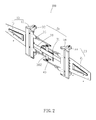
- FIG. 2 is an isometric view of the mounting device of FIG. 1 viewed from a different angle.
- FIG. 3 is an isometric view of the first fixing member in FIG. 1 .
- FIG. 4 is an exploded view of mounting device of FIG. 1 .
- FIG. 5 is an exploded view of mounting device of FIG. 2 .
- FIG. 6 an exploded view of a linking assembly in FIG. 1 .
- FIG. 7 is an enlarged view of a circle II in FIG. 5 .
- FIG. 8 is an enlarged view of a circle I in FIG. 1 .
- FIG. 9 is an isometric view of the mounting device of FIG. 2 with multiple screens in a first state.
- FIG. 10 is an isometric view of the mounting device of FIG. 1 in a second state.
- Coupled is defined as connected, whether directly or indirectly through intervening components, and is not necessarily limited to physical connections.
- the connection can be such that the objects are permanently connected or releasably connected.
- substantially is defined to be essentially conforming to the particular dimension, shape or other word that substantially modifies, such that the component need not be exact.
- substantially cylindrical means that the object resembles a cylinder, but can have one or more deviations from a true cylinder.
- comprising when utilized, means “including, but not necessarily limited to”; it specifically indicates open-ended inclusion or membership in the so-described combination, group, series and the like.
- the present disclosure is described in relation to a mounting device for multiple screens.
- FIGS. 1 and 2 illustrate a mounting device for multiple screens 100 .
- the mounting device 100 includes a first fixing member 10 , a second fixing member 20 , a third fixing member 30 , and a linking assembly 40 .
- the first fixing member 10 and the second fixing member 20 relative pivot to the third fixing member 30 , respectively.
- the third fixing member 30 can be fixed on a wall.
- the linking assembly 40 communicates with the first fixing member 10 , the second fixing member 20 , and the third fixing member 30 respectively to enable the first fixing member 10 and the second fixing member 20 to rotate relative to the third fixing member 30 .
- Each of the first fixing member 10 , the second fixing member 20 , and the third fixing member 30 fixes one screen 60 (shown in FIG. 9 ).
- FIGS. 3 and 7 illustrate that the first fixing member 10 includes a first board 11 configured to fix one screen 60 (shown in FIG. 9 ) and a first supporting portion 12 fixed to a side of the first board 11 .
- the first board 11 is in a trapeziform shape, and forms a first recess portion 115 .
- the first recess portion 115 is concaved apart from the screen 60 in the first board 11 .
- the first recess portion 115 forms a first opening 1152 for heat-dissipation of the screen 60 .
- a first bending portion 112 is located at an end of the first board 11 .
- the first supporting portion 12 includes a first connecting pillar 122 .
- the first bending portion 112 is fixed on the side of the first connecting pillar 122 .
- Two first connecting blocks 124 can be located at opposite ends of the first connecting pillar 122 .
- the first connecting block 124 is hollow and substantially L-shaped.
- An end of the connecting block 124 away from the first connecting pillar 122 defines a first coupling portion 1242 vertical to the connecting block 124 .
- a middle of the coupling portion 1242 forms a hole 1243 .
- An engaging portion 1244 is fixed on the first connecting block 124 closing the first coupling portion 1242 , a first tooth 1246 protrudes from the engaging portion 1244 .
- FIGS. 4 and 5 illustrate that the second fixing member 20 includes a second board 21 and a second supporting portion 22 fixing the second board 21 .
- the first board 11 is in a trapeziform shape.
- the second recess portion 215 is concaved apart from the screen 60 in the second board 21 .
- the second recess portion 215 forms a second opening 2152 for heat-dissipation of the screen 60 .
- a second bending portion 212 is located at an end of the second board 21 .
- a plurality of second protrusions 214 protrude from a connection portion between the second bending portion 212 and the second board 21 .
- the second supporting portion 12 includes a second connecting pillar 222 and two second connecting blocks 224 fixed at opposite ends of the second connecting pillar 222 .
- the second connecting block 224 is hollow and substantially L-shaped.
- a reinforcement 50 is located at an inner of each of the first connecting blocks 124 and the second connecting blocks 224 strengthening the first connecting blocks 124 and the second connecting blocks 224 .
- An end of the second connecting block 224 away from the second connecting pillar 222 defines a second coupling portion 2242 of which the shape is the same as the first coupling portion 1242 .
- FIGS. 1 and 2 illustrate that the third fixing member 30 includes a supporting shelf 31 , a third supporting portion 32 , a fourth supporting portion 34 , a connecting sheet 36 , and a coupling board 38 .
- the third supporting portion 32 and the fourth supporting portion 34 are fixed at opposite ends of the coupling board 38 and vertical to the coupling board 38 respectively.
- the supporting shelf 31 is fixed on the middle of the coupling board 38 and configured to support one screen 60 (shown in FIG. 9 ).
- a plank 382 fixed on the coupling board 38 is vertical to the coupling board 38 . Each of opposite ends of the plank 382 forms a protruding portion 3820 (shown in FIG. 5 ).
- FIGS. 4-5 and 7 illustrate that the third supporting portion 32 includes a third connecting pillar 322 and two third connecting blocks 324 located at two ends of the third connecting pillar 322 .
- Two first extending portions 3222 protruding from the third connecting pillar 322 are symmetrical to the coupling board 38 .
- the third connecting block 324 is hollow and substantially L-shaped.
- a third coupling portion 3242 is located at an end of the third connecting block 324 away from the third connecting pillar 322 .
- a second tooth 3246 fixed on the third coupling portion 3242 engages with the first tooth 1246 .
- the fourth supporting portion 34 includes a fourth connecting pillar 342 and two fourth connecting blocks 344 located on two ends of the fourth connecting pillar 342 .
- Two second extending portions 3422 protruding from the fourth connecting pillar 342 are symmetrical to the coupling board 38 .
- a shape of the second extending portion 3422 is the same as a shape of the first extending portion 3222 .
- Each of the second extending portions 3422 and the first extending portions 3222 defines a connecting sheet 36 protruding from the second extending portion 3422 or the first extending portion 3222 , each of the connecting sheets 36 forms a first groove 362 .
- the fourth connecting block 344 is hollow and substantially L-shaped.
- a fourth coupling portion 3442 located at an end of the fourth connecting block 344 away from the fourth connecting pillar 34 is engaged with the second coupling portion 2242 .
- a shape of the fourth coupling portion 3442 is the same as a shape of the third coupling portion 3242 .
- FIG. 6 illustrates that in this embodiment, there is two linking assemblies 40 .
- Each of the linking assemblies 40 includes a first part 42 , two second parts 44 , and two third parts 46 .
- a shape of the first part 42 is mainly a quadrate.
- Two second grooves 422 located at the two ends of the first part 42 .
- An end of each of two second parts 44 is fixed in the second groove 422 of the first part 42 and capable of rotating relative to the first part 42 , and the other end pivots to the an end of the third part 46 .
- An end of the third part 46 away from the second part 44 pivots to the first connecting pillar 122 or the second connecting pillar 222 (refer to FIG. 1 ).
- the first fixing member 10 is combined with the third fixing member 30 via the first coupling portion 1242 encircling the third coupling portion 3242 , and the first tooth 1246 engages with the second tooth 3246 .
- the second fixing member 20 is combined with the third fixing member 30 via the second coupling portion 2242 encircling the fourth coupling portion 3442 .
- the first setting 10 and the second setting 20 pivot to opposite ends of the third setting 30 respectively.
- the first part 42 of the linking assembly 40 is fixed on the protruding portion 3820 of the plank 382 and able to rotate relative to the protruding portion 3820 .
- An end of the third part 46 of the linking assembly 40 pivots to the first connecting pillar 122 or the second connecting pillar 222 .
- An end of the second part 44 away from the first part 42 is movably fixed in the first groove 362 of the connecting sheet 36 .
- the linking assembly 40 is fixed relative to the first setting 10 , the second setting 20 , and the third setting 30 . The assembly is complete.
- the third part 46 of the linking assembly 40 connecting with the first fixing member 10 rotates relative to the first fixing member 10 to drive the third part 46 of the linking assembly 40 to connecting with the second fixing member 20 to rotate the second fixing member 20 .
- the first fixing member 10 also rotates along with the second fixing member 20 (shown in FIGS. 9 and 10 ).
Landscapes
- Engineering & Computer Science (AREA)
- General Engineering & Computer Science (AREA)
- Mechanical Engineering (AREA)
- Overhead Projectors And Projection Screens (AREA)
- Devices For Indicating Variable Information By Combining Individual Elements (AREA)
Abstract
Description
Claims (14)
Applications Claiming Priority (3)
| Application Number | Priority Date | Filing Date | Title |
|---|---|---|---|
| TW103114607 | 2014-04-23 | ||
| TW103114607A TWI549513B (en) | 2014-04-23 | 2014-04-23 | A mounting apparatus for screen |
| TW103114607A | 2014-04-23 |
Publications (2)
| Publication Number | Publication Date |
|---|---|
| US20150305503A1 US20150305503A1 (en) | 2015-10-29 |
| US9625090B2 true US9625090B2 (en) | 2017-04-18 |
Family
ID=54333570
Family Applications (1)
| Application Number | Title | Priority Date | Filing Date |
|---|---|---|---|
| US14/512,910 Expired - Fee Related US9625090B2 (en) | 2014-04-23 | 2014-10-13 | Mounting device for multiple screens |
Country Status (2)
| Country | Link |
|---|---|
| US (1) | US9625090B2 (en) |
| TW (1) | TWI549513B (en) |
Cited By (1)
| Publication number | Priority date | Publication date | Assignee | Title |
|---|---|---|---|---|
| US11668431B2 (en) | 2020-04-27 | 2023-06-06 | Joshua Gardner Gilligan | Display mounting system |
Citations (16)
| Publication number | Priority date | Publication date | Assignee | Title |
|---|---|---|---|---|
| USRE36978E (en) * | 1996-04-26 | 2000-12-05 | Moscovitch; Jerry | Dual display system |
| JP2002295792A (en) | 2001-03-29 | 2002-10-09 | Armor:Kk | Holder having angle adjusting mechanism |
| US6554238B1 (en) * | 1999-11-18 | 2003-04-29 | Claiteal Pty. Limited | Support arm for visual display unit |
| TWM323552U (en) | 2007-06-04 | 2007-12-11 | Yi-Min Gung | Stand for hanging flat display monitor on wall |
| US7529083B2 (en) * | 2004-05-21 | 2009-05-05 | Samsung Electronics Co., Ltd | Supporting apparatus and monitor apparatus with the same |
| CN201281210Y (en) | 2008-08-11 | 2009-07-29 | 上海西门子医疗器械有限公司 | Suspension unit |
| CN202074200U (en) | 2011-05-27 | 2011-12-14 | 普瑭事业股份有限公司 | Information integration screen support |
| CN202171108U (en) | 2011-07-25 | 2012-03-21 | 东莞康佳模具塑胶有限公司 | Double section multi-angle adjustable wall hanging |
| CN102494332A (en) | 2011-12-27 | 2012-06-13 | 赵晨 | Energy-saving chain-grate boiler |
| US8245990B2 (en) * | 2008-02-01 | 2012-08-21 | Ming-Hsien Huang | Display mounting assembly |
| US8282052B2 (en) * | 2010-09-03 | 2012-10-09 | Ming-Hsien Huang | Screen supporting apparatus |
| CN203384602U (en) | 2013-06-24 | 2014-01-08 | 苏州夯固电器设备有限公司 | Multi-screen support |
| CN203463889U (en) | 2013-09-04 | 2014-03-05 | 姜平潮 | Desktop-type hanging rack capable of hanging multiple displays |
| US9004430B2 (en) * | 2011-09-30 | 2015-04-14 | Imperial Stamping Corporation | Articulating mount for a display |
| US9089216B2 (en) * | 2013-08-29 | 2015-07-28 | Top Victory Investment Ltd. | Holder assembly |
| US20160058183A1 (en) * | 2014-09-03 | 2016-03-03 | Hon Hai Precision Industry Co., Ltd. | Mounting device for multiple screens |
-
2014
- 2014-04-23 TW TW103114607A patent/TWI549513B/en not_active IP Right Cessation
- 2014-10-13 US US14/512,910 patent/US9625090B2/en not_active Expired - Fee Related
Patent Citations (16)
| Publication number | Priority date | Publication date | Assignee | Title |
|---|---|---|---|---|
| USRE36978E (en) * | 1996-04-26 | 2000-12-05 | Moscovitch; Jerry | Dual display system |
| US6554238B1 (en) * | 1999-11-18 | 2003-04-29 | Claiteal Pty. Limited | Support arm for visual display unit |
| JP2002295792A (en) | 2001-03-29 | 2002-10-09 | Armor:Kk | Holder having angle adjusting mechanism |
| US7529083B2 (en) * | 2004-05-21 | 2009-05-05 | Samsung Electronics Co., Ltd | Supporting apparatus and monitor apparatus with the same |
| TWM323552U (en) | 2007-06-04 | 2007-12-11 | Yi-Min Gung | Stand for hanging flat display monitor on wall |
| US8245990B2 (en) * | 2008-02-01 | 2012-08-21 | Ming-Hsien Huang | Display mounting assembly |
| CN201281210Y (en) | 2008-08-11 | 2009-07-29 | 上海西门子医疗器械有限公司 | Suspension unit |
| US8282052B2 (en) * | 2010-09-03 | 2012-10-09 | Ming-Hsien Huang | Screen supporting apparatus |
| CN202074200U (en) | 2011-05-27 | 2011-12-14 | 普瑭事业股份有限公司 | Information integration screen support |
| CN202171108U (en) | 2011-07-25 | 2012-03-21 | 东莞康佳模具塑胶有限公司 | Double section multi-angle adjustable wall hanging |
| US9004430B2 (en) * | 2011-09-30 | 2015-04-14 | Imperial Stamping Corporation | Articulating mount for a display |
| CN102494332A (en) | 2011-12-27 | 2012-06-13 | 赵晨 | Energy-saving chain-grate boiler |
| CN203384602U (en) | 2013-06-24 | 2014-01-08 | 苏州夯固电器设备有限公司 | Multi-screen support |
| US9089216B2 (en) * | 2013-08-29 | 2015-07-28 | Top Victory Investment Ltd. | Holder assembly |
| CN203463889U (en) | 2013-09-04 | 2014-03-05 | 姜平潮 | Desktop-type hanging rack capable of hanging multiple displays |
| US20160058183A1 (en) * | 2014-09-03 | 2016-03-03 | Hon Hai Precision Industry Co., Ltd. | Mounting device for multiple screens |
Cited By (1)
| Publication number | Priority date | Publication date | Assignee | Title |
|---|---|---|---|---|
| US11668431B2 (en) | 2020-04-27 | 2023-06-06 | Joshua Gardner Gilligan | Display mounting system |
Also Published As
| Publication number | Publication date |
|---|---|
| US20150305503A1 (en) | 2015-10-29 |
| TWI549513B (en) | 2016-09-11 |
| TW201541966A (en) | 2015-11-01 |
Similar Documents
| Publication | Publication Date | Title |
|---|---|---|
| US9523461B2 (en) | Mounting device for multiple screens | |
| US9233474B2 (en) | Clamping apparatus | |
| US10995787B2 (en) | Quick locking piece and display screen assembly | |
| US9561519B2 (en) | Automatic turning device and spraying system using the same | |
| US9188145B2 (en) | Board assembly with lock members | |
| US9759301B2 (en) | Clamping apparatus | |
| US20150108316A1 (en) | Portable supporting frame | |
| US9727093B2 (en) | Biaxial synchronization dual-shaft hinge | |
| US9844162B2 (en) | Sliding rail fixing structure of server cabinet | |
| US20150137545A1 (en) | Suction device | |
| US10268060B2 (en) | Frameless display device and electronic device using the same | |
| US20150192160A1 (en) | Connecting assembly and electronic device with the same | |
| US20150216071A1 (en) | Sliding rail mechanism and rack with sliding rail mechanism | |
| US9715248B2 (en) | Base for electronic device and electronic device assembly | |
| US9863574B2 (en) | Supporting structure and display device using the same | |
| US10295117B2 (en) | Labor saving device | |
| US20150083041A1 (en) | Glue applicator | |
| US9205523B2 (en) | Positioning apparatus | |
| US9625090B2 (en) | Mounting device for multiple screens | |
| US9788442B2 (en) | Housing locking apparatus | |
| US20160166056A1 (en) | Bracket | |
| US9436075B2 (en) | Imaging device and mounting apparatus | |
| US9352712B2 (en) | Car and bumper assembly of car | |
| CN203478136U (en) | Quick-connect aluminum frame construction | |
| US9845818B2 (en) | Coupling device and lamp apparatus having the same |
Legal Events
| Date | Code | Title | Description |
|---|---|---|---|
| AS | Assignment |
Owner name: HON HAI PRECISION INDUSTRY CO., LTD., TAIWAN Free format text: ASSIGNMENT OF ASSIGNORS INTEREST;ASSIGNOR:KUAN, CHANG-MING;REEL/FRAME:033938/0973 Effective date: 20140820 |
|
| STCF | Information on status: patent grant |
Free format text: PATENTED CASE |
|
| AS | Assignment |
Owner name: CLOUD NETWORK TECHNOLOGY SINGAPORE PTE. LTD., SING Free format text: ASSIGNMENT OF ASSIGNORS INTEREST;ASSIGNOR:HON HAI PRECISION INDUSTRY CO., LTD.;REEL/FRAME:045171/0306 Effective date: 20171229 |
|
| FEPP | Fee payment procedure |
Free format text: MAINTENANCE FEE REMINDER MAILED (ORIGINAL EVENT CODE: REM.); ENTITY STATUS OF PATENT OWNER: LARGE ENTITY |
|
| LAPS | Lapse for failure to pay maintenance fees |
Free format text: PATENT EXPIRED FOR FAILURE TO PAY MAINTENANCE FEES (ORIGINAL EVENT CODE: EXP.); ENTITY STATUS OF PATENT OWNER: LARGE ENTITY |
|
| STCH | Information on status: patent discontinuation |
Free format text: PATENT EXPIRED DUE TO NONPAYMENT OF MAINTENANCE FEES UNDER 37 CFR 1.362 |
|
| FP | Lapsed due to failure to pay maintenance fee |
Effective date: 20210418 |