US9623471B2 - Furnace heat exchanger attachment - Google Patents
Furnace heat exchanger attachment Download PDFInfo
- Publication number
- US9623471B2 US9623471B2 US13/247,490 US201113247490A US9623471B2 US 9623471 B2 US9623471 B2 US 9623471B2 US 201113247490 A US201113247490 A US 201113247490A US 9623471 B2 US9623471 B2 US 9623471B2
- Authority
- US
- United States
- Prior art keywords
- cell
- cell panel
- heat exchanger
- outlet
- openings
- Prior art date
- Legal status (The legal status is an assumption and is not a legal conclusion. Google has not performed a legal analysis and makes no representation as to the accuracy of the status listed.)
- Active, expires
Links
- 238000002788 crimping Methods 0.000 claims abstract description 26
- 230000007704 transition Effects 0.000 claims description 10
- 238000000034 method Methods 0.000 claims description 7
- 238000007789 sealing Methods 0.000 claims description 7
- UGFAIRIUMAVXCW-UHFFFAOYSA-N Carbon monoxide Chemical compound [O+]#[C-] UGFAIRIUMAVXCW-UHFFFAOYSA-N 0.000 description 5
- VNWKTOKETHGBQD-UHFFFAOYSA-N methane Chemical compound C VNWKTOKETHGBQD-UHFFFAOYSA-N 0.000 description 4
- 239000003546 flue gas Substances 0.000 description 3
- 239000000446 fuel Substances 0.000 description 2
- 239000003345 natural gas Substances 0.000 description 2
- 230000004075 alteration Effects 0.000 description 1
- 239000000567 combustion gas Substances 0.000 description 1
- -1 for example Substances 0.000 description 1
- 239000007789 gas Substances 0.000 description 1
- 230000000717 retained effect Effects 0.000 description 1
- 238000006467 substitution reaction Methods 0.000 description 1
- 238000003466 welding Methods 0.000 description 1
Images


Classifications
-
- B—PERFORMING OPERATIONS; TRANSPORTING
- B21—MECHANICAL METAL-WORKING WITHOUT ESSENTIALLY REMOVING MATERIAL; PUNCHING METAL
- B21D—WORKING OR PROCESSING OF SHEET METAL OR METAL TUBES, RODS OR PROFILES WITHOUT ESSENTIALLY REMOVING MATERIAL; PUNCHING METAL
- B21D39/00—Application of procedures in order to connect objects or parts, e.g. coating with sheet metal otherwise than by plating; Tube expanders
- B21D39/02—Application of procedures in order to connect objects or parts, e.g. coating with sheet metal otherwise than by plating; Tube expanders of sheet metal by folding, e.g. connecting edges of a sheet to form a cylinder
-
- B—PERFORMING OPERATIONS; TRANSPORTING
- B21—MECHANICAL METAL-WORKING WITHOUT ESSENTIALLY REMOVING MATERIAL; PUNCHING METAL
- B21D—WORKING OR PROCESSING OF SHEET METAL OR METAL TUBES, RODS OR PROFILES WITHOUT ESSENTIALLY REMOVING MATERIAL; PUNCHING METAL
- B21D53/00—Making other particular articles
- B21D53/02—Making other particular articles heat exchangers or parts thereof, e.g. radiators, condensers fins, headers
-
- F—MECHANICAL ENGINEERING; LIGHTING; HEATING; WEAPONS; BLASTING
- F28—HEAT EXCHANGE IN GENERAL
- F28D—HEAT-EXCHANGE APPARATUS, NOT PROVIDED FOR IN ANOTHER SUBCLASS, IN WHICH THE HEAT-EXCHANGE MEDIA DO NOT COME INTO DIRECT CONTACT
- F28D9/00—Heat-exchange apparatus having stationary plate-like or laminated conduit assemblies for both heat-exchange media, the media being in contact with different sides of a conduit wall
- F28D9/0031—Heat-exchange apparatus having stationary plate-like or laminated conduit assemblies for both heat-exchange media, the media being in contact with different sides of a conduit wall the conduits for one heat-exchange medium being formed by paired plates touching each other
-
- F—MECHANICAL ENGINEERING; LIGHTING; HEATING; WEAPONS; BLASTING
- F28—HEAT EXCHANGE IN GENERAL
- F28F—DETAILS OF HEAT-EXCHANGE AND HEAT-TRANSFER APPARATUS, OF GENERAL APPLICATION
- F28F9/00—Casings; Header boxes; Auxiliary supports for elements; Auxiliary members within casings
- F28F9/02—Header boxes; End plates
- F28F9/04—Arrangements for sealing elements into header boxes or end plates
- F28F9/16—Arrangements for sealing elements into header boxes or end plates by permanent joints, e.g. by rolling
- F28F9/165—Arrangements for sealing elements into header boxes or end plates by permanent joints, e.g. by rolling by using additional preformed parts, e.g. sleeves, gaskets
-
- F—MECHANICAL ENGINEERING; LIGHTING; HEATING; WEAPONS; BLASTING
- F24—HEATING; RANGES; VENTILATING
- F24H—FLUID HEATERS, e.g. WATER OR AIR HEATERS, HAVING HEAT-GENERATING MEANS, e.g. HEAT PUMPS, IN GENERAL
- F24H3/00—Air heaters
- F24H3/02—Air heaters with forced circulation
- F24H3/06—Air heaters with forced circulation the air being kept separate from the heating medium, e.g. using forced circulation of air over radiators
- F24H3/10—Air heaters with forced circulation the air being kept separate from the heating medium, e.g. using forced circulation of air over radiators by plates
- F24H3/105—Air heaters with forced circulation the air being kept separate from the heating medium, e.g. using forced circulation of air over radiators by plates using fluid fuel
-
- F—MECHANICAL ENGINEERING; LIGHTING; HEATING; WEAPONS; BLASTING
- F24—HEATING; RANGES; VENTILATING
- F24H—FLUID HEATERS, e.g. WATER OR AIR HEATERS, HAVING HEAT-GENERATING MEANS, e.g. HEAT PUMPS, IN GENERAL
- F24H8/00—Fluid heaters characterised by means for extracting latent heat from flue gases by means of condensation
-
- F—MECHANICAL ENGINEERING; LIGHTING; HEATING; WEAPONS; BLASTING
- F24—HEATING; RANGES; VENTILATING
- F24H—FLUID HEATERS, e.g. WATER OR AIR HEATERS, HAVING HEAT-GENERATING MEANS, e.g. HEAT PUMPS, IN GENERAL
- F24H9/00—Details
- F24H9/14—Arrangements for connecting different sections, e.g. in water heaters
- F24H9/146—Connecting elements of a heat exchanger
-
- Y—GENERAL TAGGING OF NEW TECHNOLOGICAL DEVELOPMENTS; GENERAL TAGGING OF CROSS-SECTIONAL TECHNOLOGIES SPANNING OVER SEVERAL SECTIONS OF THE IPC; TECHNICAL SUBJECTS COVERED BY FORMER USPC CROSS-REFERENCE ART COLLECTIONS [XRACs] AND DIGESTS
- Y02—TECHNOLOGIES OR APPLICATIONS FOR MITIGATION OR ADAPTATION AGAINST CLIMATE CHANGE
- Y02B—CLIMATE CHANGE MITIGATION TECHNOLOGIES RELATED TO BUILDINGS, e.g. HOUSING, HOUSE APPLIANCES OR RELATED END-USER APPLICATIONS
- Y02B30/00—Energy efficient heating, ventilation or air conditioning [HVAC]
-
- Y02B30/102—
-
- Y—GENERAL TAGGING OF NEW TECHNOLOGICAL DEVELOPMENTS; GENERAL TAGGING OF CROSS-SECTIONAL TECHNOLOGIES SPANNING OVER SEVERAL SECTIONS OF THE IPC; TECHNICAL SUBJECTS COVERED BY FORMER USPC CROSS-REFERENCE ART COLLECTIONS [XRACs] AND DIGESTS
- Y10—TECHNICAL SUBJECTS COVERED BY FORMER USPC
- Y10T—TECHNICAL SUBJECTS COVERED BY FORMER US CLASSIFICATION
- Y10T29/00—Metal working
- Y10T29/49—Method of mechanical manufacture
- Y10T29/4935—Heat exchanger or boiler making
Definitions
- the subject matter disclosed herein relates to furnaces. More specifically, the present disclosure relates to attachment of a heat exchanger to a cell panel of a furnace.
- a fuel for example, natural gas
- the combustion gas flue gas
- the combustion gas is routed through one or more heat exchangers which extract the heat therefrom.
- Outlets of the heat exchanger are mechanically secured to a cell panel during assembly.
- the individual heat exchanger cells are typically formed by stamping halves of the cells which are then secured together by a folded and crimped joint. Because of the shapes of the cells, the areas of the outlets of the cells where the cell halves mate are difficult to seal to the cell panel resulting in leakage between the heat exchanger cells and the cell panel and a corresponding loss of efficiency of the heat exchanger and furnace.
- an attachment between a heat exchanger and a cell panel of a furnace includes a cell panel including a plurality of cell panel openings and a heat exchanger having a plurality of cells.
- Each cell has a cell outlet insertable into a cell panel opening of the plurality of cell panel openings.
- a beveled transition is included at each cell outlet extending around a perimeter thereof to improve sealing between the cell outlet and the cell panel;
- a compressible gasket is insertable between the cell panel openings and the cell outlets and securable therein when the heat exchanger is secured to the cell panel thereby sealing between the heat exchanger and the cell panel.
- a crimping tool for securing a heat exchanger cell outlet to a cell panel of a furnace includes a male portion extending into a cell outlet and including a split die having two die halves and a die expander configured to separate the two die halves to engage an inner surface of the cell outlet.
- a female portion is configured to apply a force to the cell outlet to crimp the cell outlet to the cell panel.
- a method of securing a heat exchanger cell outlet to a cell panel of a furnace includes inserting the cell outlet through a cell panel opening and inserting a male portion of a crimping tool into the cell outlet.
- a split die of the male portion is expanded to engage and inner surface of the cell outlet and a female portion of the crimping tool is lowered to crimp the cell outlet over the cell panel opening.
- FIG. 1 is a schematic view of an embodiment of a furnace
- FIG. 2 is a schematic view of an embodiment of a heat exchanger and cell panel attachment
- FIG. 3 is an end view of an embodiment of a heat exchanger cell outlet
- FIG. 4 is a cross-sectional view of an embodiment of a cell outlet inserted in a cell panel
- FIG. 5 is a cross-sectional view of an embodiment of a crimping tool inserted into a heat exchanger cell outlet;
- FIG. 6 is a cross-sectional view of an embodiment of a crimping tool expanded in a heat exchanger cell outlet
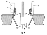
- FIG. 7 is a cross-sectional view of an embodiment of a crimping tool after completing a crimp operation.
- FIG. 1 Shown in FIG. 1 is an embodiment of a furnace 10 .
- the furnace 10 includes a burner 12 for combusting a fuel such as natural gas. Flue gas 14 exits the burner 12 and flows through a primary heat exchanger (PHX) 16 .
- the PHX 16 is a gas-to-gas heat exchanger in which the flue gas 14 flowing through the PHX 16 transfers thermal energy to the surface of the PHX 16 . The thermal energy is then dissipated from the surface of the PHX 16 into a flow of air 18 urged across the exterior of the PHX 16 by, for example, a blower 20 .
- the PHX 16 includes a number of PHX cells 22 .
- the PHX cells 22 are arranged and secured to a cell panel 24 .
- the cell panel 24 includes a plurality of cell panel openings 26 such that a cell outlet 28 of each PHX cell 22 is insertable into each cell panel opening 26 which includes an opening flange 30 .
- the PHX cell 22 is then secured to the cell panel 24 by crimping the cell outlet 28 to the opening flange 30 .
- each PHX cell 22 is formed in halves 22 a and 22 b by, for example, stamping, or other suitable process.
- the halves 22 a and 22 b are secured together to form a PHX cell 22 by, for example, welding.
- the PHX cell 22 includes a beveled transition 32 around a circumference of the cell outlet 28 and a crimping flange 34 on each lateral side of the PHX cell 22 .
- a bend angle between the crimping flange 34 of the cell outlet 28 extending through the cell panel opening 26 and the beveled transition 32 is less than approximately 90 degrees.
- a compressible gasket 36 is placed over the PHX cells 22 , the gasket 36 includes gasket openings 38 to allow the cell outlets 28 to pass through.
- the cell panel 24 is placed over the PHX cells 22 and the gasket 36 such that the gasket 36 is retained between the beveled transitions 32 of the PHX cells 22 and the cell panel 24 .
- the crimping flanges 34 are then bent over the opening flanges 30 to secure the PHX cells 22 to the cell panel 24 and to improve the sealing of the gasket 36 between the PHX cells 22 and the cell panel 24 .
- Including the gasket 26 in the assembly of the PHX cell 22 to the cell panel 24 improves sealing between the two components and prevents leakage therethrough.
- a crimping tool 40 is utilized to secure the PHX cells 22 to the cell panel 24 .
- the crimping tool 40 includes a male portion 42 insertable into the cell outlet 28 .
- the male portion 42 includes a split die 44 .
- Each half of the split die 44 has a die bevel 46 substantially matching the beveled transition 32 of the PHX cell 22 .
- FIG. 6 once the male portion 42 is inserted into the cell outlet 28 , a die expander 48 is drawn outwardly toward the cell outlet 28 thereby forcing the halves of the split die 44 apart such that the die bevel 46 engages the beveled transition 34 . This engagement provides backing support for the crimping process. As shown in FIG.
- a female portion 50 of the crimping tool 40 is lowered over the crimping flanges 34 causing the crimping flanges 34 to bend over the opening flanges 30 thus securing the PHX cell 22 to the cell panel 24 with the gasket 36 between.
- the expander 46 is moved inwardly into the PHX cell 22 and the die halves 44 return to their unexpanded position thus allowing the male portion 42 to be removed from the PHX cell 22 .
- the crimp operation as described above is performed in more than one step.
- the female portion 50 engages the crimping flange 34 and bends the crimping flange 34 relative to the opening flange 30 approximately ninety degrees.
- the die halves 44 are unexpanded allowing for removal to the crimping tool 40 .
- a second male portion 42 substantially similar to that described above is inserted into the cell outlet 28 and the dies halves 44 expanded to engage the beveled transition 32 .
- a second female portion 50 is lowered to engage the crimping flanges 34 and complete the crimp.
- the two-step process described herein is merely exemplary, and other multiple-step crimp processes are contemplated within the scope of the present disclosure.
- Providing the die bevel 46 on the split die 44 provides back up for the crimping operation without which the crimping process would collapse the crimping flanges 34 and/or the opening flanges 30 .
- use of the expandable split die 44 allows for the crimping operation to be accomplished from one side of the assembly.
Landscapes
- Engineering & Computer Science (AREA)
- Mechanical Engineering (AREA)
- Physics & Mathematics (AREA)
- Thermal Sciences (AREA)
- General Engineering & Computer Science (AREA)
- Heat-Exchange Devices With Radiators And Conduit Assemblies (AREA)
Abstract
Description
Claims (5)
Priority Applications (1)
| Application Number | Priority Date | Filing Date | Title |
|---|---|---|---|
| US13/247,490 US9623471B2 (en) | 2010-10-08 | 2011-09-28 | Furnace heat exchanger attachment |
Applications Claiming Priority (2)
| Application Number | Priority Date | Filing Date | Title |
|---|---|---|---|
| US39136110P | 2010-10-08 | 2010-10-08 | |
| US13/247,490 US9623471B2 (en) | 2010-10-08 | 2011-09-28 | Furnace heat exchanger attachment |
Publications (2)
| Publication Number | Publication Date |
|---|---|
| US20120085521A1 US20120085521A1 (en) | 2012-04-12 |
| US9623471B2 true US9623471B2 (en) | 2017-04-18 |
Family
ID=45924221
Family Applications (1)
| Application Number | Title | Priority Date | Filing Date |
|---|---|---|---|
| US13/247,490 Active 2034-07-13 US9623471B2 (en) | 2010-10-08 | 2011-09-28 | Furnace heat exchanger attachment |
Country Status (1)
| Country | Link |
|---|---|
| US (1) | US9623471B2 (en) |
Families Citing this family (1)
| Publication number | Priority date | Publication date | Assignee | Title |
|---|---|---|---|---|
| CN113175746B (en) * | 2021-05-29 | 2024-07-23 | 沧州市捷硕热能科技有限公司 | Energy-saving heating wall-mounted furnace |
Citations (8)
| Publication number | Priority date | Publication date | Assignee | Title |
|---|---|---|---|---|
| US3545424A (en) * | 1968-12-19 | 1970-12-08 | Trane Co | Hot air furnace |
| US3908629A (en) * | 1973-11-30 | 1975-09-30 | Singer Co | Hot air furnace with improved heat exchanger construction |
| US3940837A (en) * | 1973-11-30 | 1976-03-02 | The Singer Company | Hot air furnace with improved heat exchanger construction |
| US4401157A (en) * | 1979-10-12 | 1983-08-30 | Valeo | Device for tightly assembling a collector and a water box in heat exchanger |
| US4663837A (en) * | 1983-05-02 | 1987-05-12 | Snydergeneral Corporation | Apparatus for manufacturing a furnace heat exchanger and plate assembly |
| US4896411A (en) * | 1985-05-02 | 1990-01-30 | Carrier Corporation | Method of making a multiple cell condensing heat exchanger |
| US5575330A (en) * | 1993-01-22 | 1996-11-19 | Alco Industries, Inc. | Furnace heat exchanger seal and method of making same |
| US5901784A (en) * | 1995-11-02 | 1999-05-11 | Valeo Thermique Moteur | Heat exchanger with oval or oblong tubes, and a method of assembly of such a heat exchanger |
-
2011
- 2011-09-28 US US13/247,490 patent/US9623471B2/en active Active
Patent Citations (8)
| Publication number | Priority date | Publication date | Assignee | Title |
|---|---|---|---|---|
| US3545424A (en) * | 1968-12-19 | 1970-12-08 | Trane Co | Hot air furnace |
| US3908629A (en) * | 1973-11-30 | 1975-09-30 | Singer Co | Hot air furnace with improved heat exchanger construction |
| US3940837A (en) * | 1973-11-30 | 1976-03-02 | The Singer Company | Hot air furnace with improved heat exchanger construction |
| US4401157A (en) * | 1979-10-12 | 1983-08-30 | Valeo | Device for tightly assembling a collector and a water box in heat exchanger |
| US4663837A (en) * | 1983-05-02 | 1987-05-12 | Snydergeneral Corporation | Apparatus for manufacturing a furnace heat exchanger and plate assembly |
| US4896411A (en) * | 1985-05-02 | 1990-01-30 | Carrier Corporation | Method of making a multiple cell condensing heat exchanger |
| US5575330A (en) * | 1993-01-22 | 1996-11-19 | Alco Industries, Inc. | Furnace heat exchanger seal and method of making same |
| US5901784A (en) * | 1995-11-02 | 1999-05-11 | Valeo Thermique Moteur | Heat exchanger with oval or oblong tubes, and a method of assembly of such a heat exchanger |
Also Published As
| Publication number | Publication date |
|---|---|
| US20120085521A1 (en) | 2012-04-12 |
Similar Documents
| Publication | Publication Date | Title |
|---|---|---|
| US8561601B2 (en) | Heat exchanger with fastener | |
| CA2834019C (en) | Method and apparatus for suspending duct by inserted corner members | |
| US8646442B2 (en) | Clamshell heat exchanger | |
| US20020135184A1 (en) | Mechanical pipe coupling derived from a standard fitting | |
| US20080256778A1 (en) | Method for Joining Tubes | |
| JP2015513641A (en) | How to use cooling line set fitting and cooling line set fitting to join cooling lines together | |
| CA2865066C (en) | Method of manufacturing recuperator air cells | |
| US20150204621A1 (en) | Pipe connection, in particular for a heat exchanger | |
| EP2345487A9 (en) | Reflare tool and process | |
| US9623471B2 (en) | Furnace heat exchanger attachment | |
| US20160177888A1 (en) | Exhaust gas heat exchanger | |
| WO2019045917A1 (en) | High temperature capable joint assembly for use in air-to-air aftercoolers (ataac) | |
| CN101300445B (en) | Method for producing a plug connection and plug connection | |
| US20160238174A1 (en) | Flexible pipe element and method for inserting a seal in a flexible pipe element | |
| US9869417B2 (en) | Pipe coupling structure | |
| US4649894A (en) | Heat exchanger and plate assembly and method of manufacture | |
| US4663837A (en) | Apparatus for manufacturing a furnace heat exchanger and plate assembly | |
| CN103286231B (en) | Thick-wall nickel base alloy heat exchanging tube and nickel base alloy tube plate expanding-connecting technology | |
| JP5503317B2 (en) | Interlocking holding strip | |
| JP5108638B2 (en) | Piping prevention device | |
| JP5826077B2 (en) | Fluid flow member | |
| US4538338A (en) | Method for manufacturing a furnace heat exchanger and plate assembly | |
| US20140131021A1 (en) | Heat exchanger pipe and manufacturing method therefor | |
| US20140069523A1 (en) | Gas generator case repair | |
| CN107036476B (en) | Heat exchange tube, heat exchanger and method of making heat exchanger |
Legal Events
| Date | Code | Title | Description |
|---|---|---|---|
| AS | Assignment |
Owner name: CARRIER CORPORATION, CONNECTICUT Free format text: ASSIGNMENT OF ASSIGNORS INTEREST;ASSIGNORS:HAYDOCK, PAUL M.;PULLEY, STEPHEN L.;MITCHUM, JAMES J.;AND OTHERS;SIGNING DATES FROM 20101014 TO 20101015;REEL/FRAME:026984/0522 |
|
| STCF | Information on status: patent grant |
Free format text: PATENTED CASE |
|
| MAFP | Maintenance fee payment |
Free format text: PAYMENT OF MAINTENANCE FEE, 4TH YEAR, LARGE ENTITY (ORIGINAL EVENT CODE: M1551); ENTITY STATUS OF PATENT OWNER: LARGE ENTITY Year of fee payment: 4 |
|
| MAFP | Maintenance fee payment |
Free format text: PAYMENT OF MAINTENANCE FEE, 8TH YEAR, LARGE ENTITY (ORIGINAL EVENT CODE: M1552); ENTITY STATUS OF PATENT OWNER: LARGE ENTITY Year of fee payment: 8 |