US9621447B2 - Bandwidth measuring device, bandwidth measuring method and non-transitory computer readable medium - Google Patents
Bandwidth measuring device, bandwidth measuring method and non-transitory computer readable medium Download PDFInfo
- Publication number
- US9621447B2 US9621447B2 US14/705,450 US201514705450A US9621447B2 US 9621447 B2 US9621447 B2 US 9621447B2 US 201514705450 A US201514705450 A US 201514705450A US 9621447 B2 US9621447 B2 US 9621447B2
- Authority
- US
- United States
- Prior art keywords
- measurement
- bandwidth
- communication
- client device
- cutoff frequency
- Prior art date
- Legal status (The legal status is an assumption and is not a legal conclusion. Google has not performed a legal analysis and makes no representation as to the accuracy of the status listed.)
- Expired - Fee Related, expires
Links
Images


Classifications
-
- H—ELECTRICITY
- H04—ELECTRIC COMMUNICATION TECHNIQUE
- H04W—WIRELESS COMMUNICATION NETWORKS
- H04W24/00—Supervisory, monitoring or testing arrangements
- H04W24/08—Testing, supervising or monitoring using real traffic
-
- H—ELECTRICITY
- H04—ELECTRIC COMMUNICATION TECHNIQUE
- H04L—TRANSMISSION OF DIGITAL INFORMATION, e.g. TELEGRAPHIC COMMUNICATION
- H04L43/00—Arrangements for monitoring or testing data switching networks
- H04L43/08—Monitoring or testing based on specific metrics, e.g. QoS, energy consumption or environmental parameters
- H04L43/0876—Network utilisation, e.g. volume of load or congestion level
- H04L43/0894—Packet rate
-
- H—ELECTRICITY
- H04—ELECTRIC COMMUNICATION TECHNIQUE
- H04L—TRANSMISSION OF DIGITAL INFORMATION, e.g. TELEGRAPHIC COMMUNICATION
- H04L43/00—Arrangements for monitoring or testing data switching networks
- H04L43/08—Monitoring or testing based on specific metrics, e.g. QoS, energy consumption or environmental parameters
- H04L43/0823—Errors, e.g. transmission errors
- H04L43/0847—Transmission error
-
- H—ELECTRICITY
- H04—ELECTRIC COMMUNICATION TECHNIQUE
- H04L—TRANSMISSION OF DIGITAL INFORMATION, e.g. TELEGRAPHIC COMMUNICATION
- H04L47/00—Traffic control in data switching networks
- H04L47/10—Flow control; Congestion control
- H04L47/11—Identifying congestion
Definitions
- the present invention relates to a bandwidth measuring device, a bandwidth measuring method and a non-transitory computer readable medium.
- a bandwidth measuring device including: an extracting unit that extracts, as a cutoff frequency, a highest frequency component among frequency components obtained by performing Fourier transform on transition data which indicates a transition of communication congestion traffic with respect to a time in a communication network to be used a determining unit that determines, on the basis of a relationship between an error ratio and the number of measurement times in a cycle corresponding to the cutoff frequency, a minimum value of the number of measurement times that satisfy a given error ratio; a setting unit that sets each of a measurement cycle and a measurement time so as to satisfy both conditions of a maximum value in the measurement cycle determined on the basis of the cutoff frequency and the minimum value of the number of measurement times in the cycle corresponding to the cutoff frequency determined by the determining unit; and a measuring unit that measures a bandwidth of communication performed by using the communication network, on the basis of the measurement cycle and the measurement time set by the setting unit.
- FIG. 1 is a system block diagram of an information distribution system according to an exemplary embodiment of the present invention
- FIG. 2 is a diagram illustrating an example of the hardware configuration of each of an information distribution server and a client device
- FIG. 3 is a diagram illustrating an example of a distribution video data management table
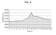
- FIG. 4 is a diagram illustrating an example of communication congestion status transition data
- FIG. 5 is a sequence diagram of video distribution processing according to a first exemplary embodiment
- FIG. 6 is a sequence diagram of video distribution processing according to the first exemplary embodiment
- FIG. 7 is a flowchart of measurement time setting processing
- FIG. 8 is a sequence diagram of video distribution processing according to a second exemplary embodiment
- FIG. 9 is a sequence diagram of video distribution processing according to the second exemplary embodiment.
- FIG. 10 is a sequence diagram of measurement time setting processing according to a third exemplary embodiment
- FIG. 11 is a sequence diagram of video distribution processing according to the third exemplary embodiment.
- FIG. 12 is a graph of a function fM(u).
- FIG. 13 is a graph illustrating the relationship between M and the error ratio.
- FIG. 1 is a system block diagram of an information distribution system 1 according to an exemplary embodiment of the present invention.
- the information distribution system 1 includes an information distribution server 10 , one or more base station devices 30 , and one or more client devices 40 .
- the information distribution server 10 and each base station device 30 communicate with each other via a network 20 , such as an optical communication network, and a base station device 30 and a client device 40 perform wireless communication, such as mobile communication or wireless LAN communication, with each other, thereby implementing communication between the information distribution server 10 and each client device 40 .
- a network 20 such as an optical communication network
- wireless communication such as mobile communication or wireless LAN communication
- the information distribution server 10 is a computer that stores data, such as video, and provides data in response to a request from a client device 40 .
- the information distribution server 10 selects qualities (such as the resolution and the size) of data (video) requested by the client device 40 , on the basis of the communication bandwidth (BW) between the client device 40 and the information distribution server 10 , and provides data of the selected qualities to the client device 40 .
- qualities such as the resolution and the size
- the base station device 30 is a device that performs wired communication with the information distribution server 10 and performs wireless communication, such as mobile communication, with each client device 40 .
- Wireless communication between the base station device 30 and the client device 40 may be performed by using various communication systems, such as 30 and 40 mobile communication.
- the client device 40 is a computer, such as a cellular phone (including a multi-function cellular phone), a tablet terminal, or a personal computer, operated by a user.
- the client device 40 performs wireless communication with the base station device 30 and performs data communication with the information distribution server 10 via the base station device 30 . This enables the client device 40 to receive distribution of, for example, video, from the information distribution server 10 .
- the client device 40 also measures the communication bandwidth (BW) between the client device 40 and the information distribution server 10 for a preset measurement time ( ⁇ ) at regular preset measurement intervals (T).
- the measurement interval (T) and the measurement time ( ⁇ ) are set on the basis of communication congestion status transition data (Congestion Profile) indicating the transition of the congestion status of a network with respect to the time. Details of processing for setting the measurement interval (T) and the measurement time ( ⁇ ) will be discussed later.
- An example of the processing performed by the information distribution system 1 is as follows.
- the client device 40 Upon receiving a request to receive video distribution from the information distribution server 10 from a user, the client device 40 establishes communication with the information distribution server 10 . Then, the client device 40 measures the communication bandwidth (BW) between the information distribution server 10 and the client device 40 , on the basis of the measurement interval (T) and the measurement time (T) which are optimized to a temporal transition of the congestion status (for example, traffic) of a network. Then, the client device 40 sends the measured communication bandwidth, together with specifying information (for example, URL) which specifies the video to be requested, to the information distribution server 10 .
- BW communication bandwidth
- T measurement interval
- T measurement time
- the client device 40 sends the measured communication bandwidth, together with specifying information (for example, URL) which specifies the video to be requested, to the information distribution server 10 .
- the information distribution server 10 selects video qualities (such as the resolution and the hit rate) of the video specified by the specifying information, on the basis of the communication bandwidth received from the client device 40 , and sends a video-distribution URL corresponding to the selected video qualities to the client device 40 .
- the client device 40 accesses the video-distribution URL sent from the information distribution server 10 and receives the distribution of the video of qualities which are optimized to the communication bandwidth between the client device 40 and the information distribution server 10 .
- the client device 40 then plays back the distributed video (for example, by stream playback).
- the information distribution server 10 includes a controller 11 , a storage unit 12 , and a communication unit 13 .
- the controller 11 includes a CPU (Central Processing Unit) and executes various arithmetic operations and also controls the individual elements of the information distribution server 10 , on the basis of a program stored in the storage unit 12 .
- CPU Central Processing Unit
- the storage unit 12 stores a program, such as an operating system of the information distribution server 10 , and data therein, and is also used as a work memory of the controller 11 .
- the program may be stored in an information storage medium, such as an optical disc, a magnetic disk, magnetic tape, a magneto-optical disk, or a flash memory, and be supplied to the information distribution server 10 .
- the program may be supplied to the information distribution server 10 via data communication means, such as the Internet.
- data communication means such as the Internet.
- video data (video files) and a distribution video data management table indicating qualities of video data to be distributed which are determined in accordance with each communication bandwidth, are stored.
- FIG. 3 An example of the distribution video data management table is shown in FIG. 3 .
- the file name of video data, qualities (frame rate, resolution, and bit rate), ranks (ranges) of communication bandwidths, and video-distribution URLs are stored in association with each other.
- the rank of a communication bandwidth may be determined for each communication system.
- the communication unit 13 is implemented as a network interface card, and performs data communication with the base station device 30 and the like via a network and also performs data communication with the client device 40 and the like via the base station device 30 .
- the client device 40 includes a controller 41 , a storage unit 42 , a communication unit 43 , an input unit 44 , and a display unit 45 .
- the controller 41 includes a CPU (Central Processing Unit) and executes various arithmetic operations and also controls the individual elements of the client device 40 , on the basis of a program stored in the storage unit 42 .
- CPU Central Processing Unit
- the storage unit 42 stores a program, such as en operating system of the client device 40 , and data therein, and is also used as a work memory of the controller 41 .
- the program may be stored in an information storage medium, such as an optical disc, a magnetic disk, magnetic tape, a magneto-optical disk, or a flash memory, and be supplied to the client device 40 .
- the program may be supplied to the client device 40 via data communication means, such as the Internet.
- transition data indicating the congestion status of a network with respect to the time may be stored.
- FIG. 4 An example of the communication congestion status transition data is shown in FIG. 4 .
- the horizontal axis indicates the time (0 to 23 (hour)) and the vertical axis indicates the communication congestion traffic.
- the communication congestion traffic may be data based on, for example, packets to be communicated, loss packets, packet delay time.
- This communication congestion status transition data may be obtained as a result of the client device 40 measuring the communication congestion on the basis of packets regularly sent to the information distribution server 10 , or may be obtained from another device or a storage medium.
- the communication congestion status transition data may be set according to the month or the day of the week.
- the communication unit 43 includes, for example, a wireless communication antenna, and communicates with the base station device 30 via the wireless communication antenna.
- the input unit 44 is implemented by an input device, such as a touch panel or a keyboard, and receives input of an operation from a user.
- the display unit 45 is implemented by a display device, such as a liquid crystal display, and displays results (screen) of information processing executed by the controller 41 .
- the first exemplary embodiment is concerned with an example of processing in a case in which the client device 40 measures the communication bandwidth (BW) when sending a video distribution request and sends information concerning the communication bandwidth (BW) to the information distribution server 10 .
- FIGS. 5 and 6 A sequence diagram of video distribution processing to be executed when the client device 40 sends a video distribution request to the information distribution server 10 is shown in FIGS. 5 and 6 .
- the client device 40 first executes measurement time setting processing for setting the time interval (T) and the measurement time (T) at and for which the communication bandwidth (BW) is measured (S 101 ). Details of this measurement time setting processing will be discussed later.
- the client device 40 Upon receiving a video distribution request from a user (S 102 ), the client device 40 accesses the information distribution server 10 based on a link (URL) concerning the video distribution request and sends a video distribution request and a connection establishment request to the information distribution server 10 (S 103 ).
- a link URL
- the information distribution server 10 Upon receiving a connection establishment request packet from the client device 40 , the information distribution server 10 sends an acknowledgement response (ACK) to the connection establishment request packet to the client device 40 (S 104 ).
- ACK acknowledgement response
- the client device 40 Upon receiving the acknowledgement response (ACK) to the connection establishment request packet from the information distribution server 10 , the client device 40 mutually identifies a communication port used for communication with the information distribution server 10 (S 105 ).
- the client device 40 sends a dummy packet to which a time stamp for a sending time is appended to the information distribution server 10 (S 108 ).
- the information distribution server 10 Upon receiving the dummy packet from the client device 40 , the information distribution server 10 appends a time stamp for a sending time to an acknowledgement response (ACK) to the received dummy packet and sends the acknowledgement response (ACK) to the client device 40 (S 109 ).
- ACK acknowledgement response
- the client device 40 Upon receiving the acknowledgement response (ACK) to the dummy packet from the information distribution server 10 , the client device 40 calculates a round-trip time (RTT) on the basis of the time interval between the time indicated by the time stamp of the dummy packet and that of the acknowledgement response (ACK), and records the calculated round-trip time (RTT) (S 110 ). If the client device 40 has failed to receive ACK in response to the sent dummy packet, it may assume that packet loss has occurred and also record information concerning the occurrence of packet loss. If the timer tB has not reached ⁇ (S 111 : N), the client device 40 returns to S 108 . If the timer tB has reached ⁇ (S 111 : Y), the client device 40 determines whether or not the timer tA has reached T (S 112 ).
- RTT round-trip time
- the client device 40 waits until the timer tA reaches T. If the timer tA has reached T (S 112 : Y), the client device 40 determines whether or not a measurement completion condition is satisfied (S 113 ). For example, if the number of times dummy packets have been sent is equal to or greater than a number threshold, or if the time elapsed after measurements have started is equal to or greater than a time threshold, the client device 40 may determine that the measurement completion condition is satisfied.
- the client device 40 If the measurement completion condition is not satisfied in S 113 (S 113 : N), the client device 40 returns to S 106 . If the measurement completion condition is satisfied (S 113 : Y), the client device 40 measures the communication bandwidth (BW) on the basis of the recorded RTT and the packet loss ratio (p) (S 114 ).
- the communication bandwidth (BW) may be calculated by, for example, the following equation (1).
- RTT is the average (or may be the median) of recorded RTTs
- p is the ratio of loss packets to the number of sent packets
- MSS Maximum Segment Size
- the equation used for calculating the communication bandwidth (BW) is not restricted to equation (1), and another equation may be used.
- step S 114 Operations after step S 114 will be described below with reference to FIG. 6 .
- the client device 40 sends communication status information indicating the communication bandwidth (BW) calculated in S 114 to the information distribution server 10 (S 115 ).
- the communication status information may include information concerning the communication system of wireless communication (for example, the mobile communication system) used by the client device 40 .
- the information distribution server 10 Upon receiving the communication status information including the information concerning the communication system and the communication bandwidth (BW) from the client device 40 , the information distribution server 10 selects video qualities corresponding to the received communication system and communication bandwidth (BW) for the video data requested by the client device 40 by referring to the video distribution data management table (S 116 ). For example, the information distribution server 10 may determine under which one of the ranks set for each communication system (for example, in mobile communication system A, L (lower than BWA 1 ), M (BWA 1 or higher and lower than BMA 2 ), and H (BWA 2 or higher) the communication bandwidth (BW) is classified, and may select video qualities (frame rate, resolution, and bit rate) corresponding to a set of the communication system and the rank.
- the information distribution server 10 may determine under which one of the ranks set for each communication system (for example, in mobile communication system A, L (lower than BWA 1 ), M (BWA 1 or higher and lower than BMA 2 ), and H (BWA 2 or higher) the communication bandwidth
- the information distribution server 10 obtains the distribution URL for distributing the video data of the video qualities selected in S 116 from the video distribution data management table (S 117 ), and sends the obtained distribution URL to the client device 40 (S 118 ) so as to redirect the client device 40 to the distribution URL.
- the client device 40 accesses the distribution URL sent from the information distribution server 10 (S 119 ), receives the distribution of the video data linked to the distribution URL from the information distribution server 10 (S 120 ), and plays back the video data (S 121 ).
- the above-described processing is the overall flow of the video distribution processing to be executed when the client device 40 sends a video distribution request to the information distribution server 10 .
- the client device 40 obtains communication congestion status transition data (see FIG. 4 ) indicating the transition of the congestion status of a network with respect to the time (S 1001 ).
- the communication congestion status transition data may be obtained as a result of the client device 40 measuring the communication congestion on the basis of packets regularly sent to the information distribution server 10 , or may be obtained from another device or a storage medium. If the communication congestion status transition data is set according to the month or the day of the week, the client device 40 may obtain the communication congestion status transition data at a current date.
- a network valuation function NetEst(t) is expressed by the following equation (3) by using s(t) and c(t).
- the result of performing Fourier transform on NetEst (t) is expressed by equation (4).
- sinc is a sinc function
- u is a frequency component
- * is a convolution operator
- S(u) and C(u) are the results of performing Fourier transform on s(t) and c(t), respectively.
- the client device 40 performs Fourier transform (for example, EFT) on the communication congestion status transition data so as to calculate the cutoff frequency fc (S 1002 ).
- the cutoff frequency fc is the highest frequency component of C(u) obtained by performing Fourier transform on the communication congestion status transition data c(t).
- M the error ratio
- e ( M ) 1 ⁇ ( fM ( fc ) ⁇ f 1( fc )) (7)
- FIG. 13 illustrates the relationship between M and the error ratio.
- the horizontal axis indicates N, and the vertical axis indicates the error ratio. If a desired error ratio is specified, the corresponding M is determined. For example, in the example shown in FIG. 13 , if 0.1% or lower is specified as the error ratio, the corresponding M is about 43 or higher.
- the client device 40 determines the minimum value Mmin of the number of measurement times M in the cycle (1/fc) that satisfy a specified error ratio (S 1003 ).
- the above-described processing refers to the flow of processing according to the first exemplary embodiment. According to the processing of the first exemplary embodiment, it is possible to distribute video of a quality suited to the communication bandwidth (BW) at a time when the client device 40 has sent a video distribution request to the information distribution server 10 . Additionally, each client device 40 measures the communication bandwidth (BW), thereby preventing the concentration of the processing load on the information distribution server 10 .
- BW communication bandwidth
- the second exemplary embodiment is concerned with an example of processing in a case in which the information distribution server 10 measures the communication bandwidth (BW) when receiving a video distribution request.
- BW communication bandwidth
- FIGS. 8 and 9 A sequence diagram of video distribution processing to be executed when the client device 40 sends a video distribution request to the information distribution server 10 is shown in FIGS. 8 and 9 .
- the information distribution server 10 first executes measurement time setting processing for setting the time interval (I) and the measurement time ( ⁇ ) at and for which the communication bandwidth (BW) is measured (S 201 ). Details of this measurement time setting processing are indicated by the flowchart of FIG. 7 , and an explanation thereof will thus be omitted here.
- the client device 40 Upon receiving a video distribution request from a user (S 202 ), the client device 40 accesses the information distribution server 10 based on a link (URL) concerning the video distribution request and sends a video distribution request and a connection establishment request to the information distribution server 10 (S 203 ).
- a link URL
- the information distribution server 10 Upon receiving a connection establishment request packet from the client device 40 , the information distribution server 10 sends an acknowledgement response (ACK) to the connection establishment request packet to the client device 40 (S 204 ).
- ACK acknowledgement response
- the client device 40 Upon receiving the acknowledgement response (ACK) to the connection establishment request packet from the information distribution server 10 , the client device 40 mutually identifies a communication port used for communication with the information distribution server 10 (S 205 ).
- the information distribution server 10 sends a dummy packet to which a time stamp for a sending time is appended to the client device 40 (S 208 ).
- the client device 40 Upon receiving the dummy packet from the information distribution server 10 , the client device 40 appends a time stamp for a sending time to an acknowledgement response (ACK) to the received dummy packet and sends the acknowledgement response (ACK) to the information distribution server 10 (S 209 ).
- ACK acknowledgement response
- the information distribution server 10 Upon receiving the acknowledgement response (ACK) to the dummy packet from the client device 40 , the information distribution server 10 calculates a round-trip time (RTT) on the basis of the time interval between the time indicated by the time stamp of the dummy packet and that of the acknowledgement response (ACK), and records the calculated round-trip time (RTT) (S 210 ). If the information distribution server 10 has failed to receive ACK in response to the sent dummy packet, it may assume that packet loss has occurred and also record information concerning the occurrence of packet loss. If the timer tB has not reached ⁇ (S 211 : N), the information distribution server 10 returns to S 208 . If the timer tB has reached ⁇ (S 211 : Y), the information distribution server 10 determines whether or not the timer tA has reached T (S 212 ).
- RTT round-trip time
- the information distribution server 10 waits until the timer tA reaches T. If the timer tA has reached T (S 212 : Y), the information distribution server 10 determines whether or not a measurement completion condition is satisfied (S 213 ). For example, if the number of times dummy packets have been sent is equal to or greater than a number threshold, or if the time elapsed after measurements have started is equal to or greater than a time threshold, the information distribution server 10 may determine that the measurement completion condition is satisfied.
- the information distribution server 10 If the measurement completion condition is not satisfied in S 213 (S 213 : N), the information distribution server 10 returns to S 206 . If the measurement completion condition is satisfied (S 213 : Y), the information distribution server 10 measures the communication bandwidth (BW) on the basis of the recorded RTT and the packet loss ratio (p) (S 214 ). For example, the communication bandwidth (BW) may be calculated by, for example, the above-described equation (1).
- step S 214 Operations after step S 214 will be described below with reference to FIG. 9 .
- the information distribution server 10 selects video qualities corresponding to the above-described communication system and communication bandwidth (BW) for the video data requested by the client device 40 by referring to the video distribution data management table (S 215 ).
- the information distribution server 10 may determine under which one of the ranks set for each communication system (for example, in mobile communication system A, L (lower than BWA 1 ), M (BWA 1 or higher and lower than BMA 2 ), and H (BWA 2 or higher) the communication bandwidth (BW) is classified, and may select video qualities (frame rate, resolution, and bit rate) corresponding to a set of the communication system and the rank.
- the information distribution server 10 obtains the distribution URL for distributing the video data of the video qualities selected in S 215 from the video distribution data management table (S 216 ), and sends the obtained distribution URL to the client device 40 (S 217 ) so as to redirect the client device 40 to the distribution URL.
- the client device 40 accesses the distribution URL sent from the information distribution server 10 (S 218 ), receives the distribution of the video data linked to the distribution URL from the information distribution server 10 (S 219 ), and plays back the video data (S 220 ).
- the above-described processing refers to the overall flow of the video distribution processing to be executed when the client device 40 sends a video distribution request to the information distribution server 10 .
- the third exemplary embodiment is concerned with an example of processing in a case in which the client device 40 measures the communication bandwidth (BW) on a regular basis and stores it prior to the sending of a video distribution request, and sends information concerning the stored latest communication bandwidth (BW) to the information distribution server 10 when receiving a video distribution request.
- BW communication bandwidth
- FIG. 10 A sequence diagram of measurement processing for measuring the communication bandwidth (BW) on a regular basis executed by the client device 40 is shown in FIG. 10 .
- the client device 40 first executes measurement time setting processing for setting the time interval (T) and the measurement time ( ⁇ ) at and for which the communication bandwidth (BW) measured (S 301 ). Details of this measurement time setting processing are indicated by the flowchart of FIG. 7 , and an explanation thereof will thus be omitted here.
- the client device 40 waits. If the update timing for updating the communication bandwidth (BW) has arrived (S 302 : Y), the client device 40 accesses the information distribution server 10 and sends a connection establishment request to the information distribution server 10 (S 303 ).
- the information distribution server 10 Upon receiving a connection establishment request packet from the client device 40 , the information distribution server 10 sends an acknowledgement response (ACK) to the connection establishment request packet to the client device 40 (S 304 ).
- ACK acknowledgement response
- the client device 40 Upon receiving the acknowledgement response (ACK) to the connection establishment request packet from the information distribution server 10 , the client device 40 mutually identifies a communication port used for communication with the information distribution server 10 (S 305 ).
- the client device 40 sends a dummy packet to which a time stamp for a sending time is appended to the information distribution server 10 (S 308 ).
- the information distribution server 10 Upon receiving the dummy packet from the client device 40 , the information distribution server 10 appends a time stamp for a sending time to an acknowledgement response (ACK) to the received dummy packet and sends the acknowledgement response (ACK) to the client device 40 (S 309 ).
- ACK acknowledgement response
- the client device 40 Upon receiving the acknowledgement response (ACK) to the dummy packet from the information distribution server 10 , the client device 40 calculates a round-trip time (RTT) on the basis of the time interval between the time indicated by the time stamp of the dummy packet and that of the acknowledgement response (ACK), and records the calculated round-trip time (PTT) (S 310 ). If the client device 40 has failed to receive ACK in response to the sent dummy packet, it may assume that packet loss has occurred and also record information concerning the occurrence of packet loss. If the timer tB has not reached ⁇ (S 311 : N), the client device 40 returns to S 303 . If the timer tB has reached ⁇ (S 311 : Y), the client device 40 determines whether or not the timer tA has reached T (S 312 ).
- RTT round-trip time
- the client device 40 waits until the timer tA reaches T. If the timer tA has reached T (S 312 : Y), the client device 40 determines whether or not a measurement completion condition is satisfied (S 313 ). For example, if the number of times dummy packets have been sent is equal to or greater than a number threshold, or if the time elapsed after measurements have started is equal to or greater than a time threshold, the client device 40 may determine that the measurement completion condition is satisfied.
- the client device 40 If the measurement completion condition is not satisfied in S 313 (S 313 : N), the client device 40 returns to S 306 . If the measurement completion condition is satisfied (S 313 : Y), the client device 40 measures the communication bandwidth (BW) on the basis of the recorded RTT and the packet loss ratio (p) (S 314 ).
- the communication bandwidth (BW) may be calculated by, for example, the above-described equation (1).
- the client device 40 stores the calculated latest communication bandwidth (BW) in the storage unit 42 (overwrites the communication bandwidth (BW) in the storage unit 42 ), and then returns to S 302 .
- the above-described processing refers to measurement processing for measuring the communication bandwidth (BW) on a regular basis executed by the client device 40 .
- the client device 40 upon receiving a video distribution request from a user (S 401 ), the client device 40 sends communication status information indicating the latest communication bandwidth (BW) stored in the storage unit 42 to the information distribution server 10 (S 402 ).
- the communication status information may include information concerning the communication system of wireless communication (for example, the mobile communication system) used by the client device 40 .
- the information distribution server 10 Upon receiving the communication status information including information concerning the communication system and the communication bandwidth (BW) from the client device 40 , the information distribution server 10 selects video qualities corresponding to the above-described communication system and communication bandwidth (BW) for the video data requested by the client device 40 by referring to the video distribution data management table (S 403 ). For example, the information distribution server 10 may determine under which one of the ranks set for each communication system (for example, in mobile communication system A, L (lower than BWA 1 ), M (BWA 1 or higher and lower than BMA 2 ), and H (BWA 2 or higher)) the communication bandwidth (BW) is classified, and may select video qualities (frame rate, resolution, and bit rate) corresponding to a set of the communication system and the rank.
- the information distribution server 10 may determine under which one of the ranks set for each communication system (for example, in mobile communication system A, L (lower than BWA 1 ), M (BWA 1 or higher and lower than BMA 2 ), and H (BWA 2 or higher)
- the information distribution server 10 obtains the distribution URL for distributing the video data of the video qualities selected in S 403 from the video distribution data management table (S 404 ), and sends the obtained distribution URL to the client device 40 (S 405 ) so as to redirect the client device 40 to the distribution URL.
- the client device 40 accesses the distribution URL sent from the information distribution server 10 (S 406 ), receives the distribution of the video data linked to the distribution. URL from the information distribution server 10 (S 407 ), and plays back the video data (S 408 ).
- the above-described processing refers to the flow of the video distribution processing to be executed when the client device 40 sends a video distribution request to the information distribution server 10 in the third exemplary embodiment.
- the client device 40 since the client device 40 measures and stores the communication bandwidth (BW) in advance, it is able to immediately send the communication bandwidth (BW) to the information distribution server 10 when sending a video distribution request. This makes it possible to reduce the wait time until video is distributed to be shorter than that of the first exemplary embodiment.
- the present invention is not restricted to the above-described exemplary embodiments.
- the client device 40 performs wireless data communication has been discussed.
- the client device 40 may perform wired data communication.
- timings at which the client device 40 updates the communication bandwidth may include, not only regular timings, but also times at which a predetermined event occurs (for example, when a predetermined operation is received from a user or when the base station device 30 to be communicated is changed).
- data to be distributed is not restricted to video data, and may be another type of data.
Landscapes
- Engineering & Computer Science (AREA)
- Computer Networks & Wireless Communication (AREA)
- Signal Processing (AREA)
- Environmental & Geological Engineering (AREA)
- Data Exchanges In Wide-Area Networks (AREA)
- Two-Way Televisions, Distribution Of Moving Picture Or The Like (AREA)
- Mobile Radio Communication Systems (AREA)
Abstract
Description
T≦1/(2·fc) (5)
τ(M)=1/(M·fc) (6)
e(M)=1−(fM(fc)−f1(fc)) (7)
e(M)=1−(sinc(π/M)−sinc(π))=1−sinc(π/M)
Claims (9)
Applications Claiming Priority (3)
| Application Number | Priority Date | Filing Date | Title |
|---|---|---|---|
| JP2013-002921 | 2013-01-10 | ||
| JP2013002921A JP5928349B2 (en) | 2013-01-10 | 2013-01-10 | Bandwidth measuring device and program |
| PCT/JP2013/071039 WO2014109085A1 (en) | 2013-01-10 | 2013-08-02 | Bandwidth measurement device and program |
Related Parent Applications (1)
| Application Number | Title | Priority Date | Filing Date |
|---|---|---|---|
| PCT/JP2013/071039 Continuation WO2014109085A1 (en) | 2013-01-10 | 2013-08-02 | Bandwidth measurement device and program |
Publications (2)
| Publication Number | Publication Date |
|---|---|
| US20150236938A1 US20150236938A1 (en) | 2015-08-20 |
| US9621447B2 true US9621447B2 (en) | 2017-04-11 |
Family
ID=51166751
Family Applications (1)
| Application Number | Title | Priority Date | Filing Date |
|---|---|---|---|
| US14/705,450 Expired - Fee Related US9621447B2 (en) | 2013-01-10 | 2015-05-06 | Bandwidth measuring device, bandwidth measuring method and non-transitory computer readable medium |
Country Status (5)
| Country | Link |
|---|---|
| US (1) | US9621447B2 (en) |
| JP (1) | JP5928349B2 (en) |
| AU (1) | AU2013373348B2 (en) |
| SG (1) | SG11201504224VA (en) |
| WO (1) | WO2014109085A1 (en) |
Families Citing this family (9)
| Publication number | Priority date | Publication date | Assignee | Title |
|---|---|---|---|---|
| CN104301924B (en) * | 2013-07-19 | 2019-07-23 | 中兴通讯股份有限公司 | Call processing method, device and terminal |
| CN105099602A (en) * | 2014-04-25 | 2015-11-25 | 阿里巴巴集团控股有限公司 | File transmission method based on network speed and system |
| US9935730B1 (en) * | 2014-05-12 | 2018-04-03 | Google Llc | Systems and methods for using radio layer information to enhance network transfer protocols |
| US10075877B1 (en) | 2014-05-12 | 2018-09-11 | Google Llc | Systems and methods for using radio layer information to enhance network transfer protocols |
| CN105553781B (en) * | 2016-01-12 | 2019-12-06 | 腾讯科技(深圳)有限公司 | method and device for measuring bottleneck bandwidth |
| EP3471456B1 (en) * | 2016-07-22 | 2023-11-22 | Huawei Technologies Co., Ltd. | Congestion control method, base station, and terminal |
| CN106302017B (en) * | 2016-08-18 | 2019-10-08 | 成都网优力软件有限公司 | The small capaciated flow network velocity-measuring system of high concurrent and method |
| CN110109395B (en) * | 2019-05-08 | 2021-08-24 | 广东电网有限责任公司 | Method, apparatus, device and storage medium for acquiring frequency bandwidth of a process |
| CN110912820B (en) * | 2019-10-30 | 2021-08-06 | 深圳马可孛罗科技有限公司 | Distributed routing method, distributed routing device, and computer-readable storage medium |
Citations (4)
| Publication number | Priority date | Publication date | Assignee | Title |
|---|---|---|---|---|
| JP2000106557A (en) | 1998-07-28 | 2000-04-11 | Fujitsu Ltd | Communication performance measuring device and its measuring method |
| US20080219164A1 (en) * | 2007-03-06 | 2008-09-11 | Nec Corporation | Communication terminal which perform low-delay communication |
| US20100142395A1 (en) * | 2008-12-09 | 2010-06-10 | Fujitsu Limited | Band measurement method and storage medium |
| US20130223221A1 (en) * | 2012-02-27 | 2013-08-29 | Verizon Patent And Licensing Inc. | Traffic Policing For MPLS-Based Network |
Family Cites Families (1)
| Publication number | Priority date | Publication date | Assignee | Title |
|---|---|---|---|---|
| JP5169441B2 (en) * | 2008-04-24 | 2013-03-27 | 日本電気株式会社 | Network quality measurement system, network quality measurement method, and network quality measurement program |
-
2013
- 2013-01-10 JP JP2013002921A patent/JP5928349B2/en not_active Expired - Fee Related
- 2013-08-02 SG SG11201504224VA patent/SG11201504224VA/en unknown
- 2013-08-02 WO PCT/JP2013/071039 patent/WO2014109085A1/en not_active Ceased
- 2013-08-02 AU AU2013373348A patent/AU2013373348B2/en not_active Ceased
-
2015
- 2015-05-06 US US14/705,450 patent/US9621447B2/en not_active Expired - Fee Related
Patent Citations (5)
| Publication number | Priority date | Publication date | Assignee | Title |
|---|---|---|---|---|
| JP2000106557A (en) | 1998-07-28 | 2000-04-11 | Fujitsu Ltd | Communication performance measuring device and its measuring method |
| US6757255B1 (en) | 1998-07-28 | 2004-06-29 | Fujitsu Limited | Apparatus for and method of measuring communication performance |
| US20080219164A1 (en) * | 2007-03-06 | 2008-09-11 | Nec Corporation | Communication terminal which perform low-delay communication |
| US20100142395A1 (en) * | 2008-12-09 | 2010-06-10 | Fujitsu Limited | Band measurement method and storage medium |
| US20130223221A1 (en) * | 2012-02-27 | 2013-08-29 | Verizon Patent And Licensing Inc. | Traffic Policing For MPLS-Based Network |
Also Published As
| Publication number | Publication date |
|---|---|
| AU2013373348A1 (en) | 2015-05-21 |
| WO2014109085A1 (en) | 2014-07-17 |
| US20150236938A1 (en) | 2015-08-20 |
| JP5928349B2 (en) | 2016-06-01 |
| SG11201504224VA (en) | 2015-07-30 |
| AU2013373348B2 (en) | 2015-11-26 |
| JP2014135656A (en) | 2014-07-24 |
Similar Documents
| Publication | Publication Date | Title |
|---|---|---|
| US9621447B2 (en) | Bandwidth measuring device, bandwidth measuring method and non-transitory computer readable medium | |
| CN111628847B (en) | Data transmission method and device | |
| EP2757740B1 (en) | Streaming media transmission quality evaluation and information acquisition method, relevant device and system | |
| EP2323281B1 (en) | System for measuring the transmission bandwidth for multimedia streaming and method for same | |
| US9055466B2 (en) | Cognitive data delivery optimizing system | |
| US7733785B2 (en) | Method and system for dynamically adjusting packet size to decrease delays of streaming data transmissions on noisy transmission lines | |
| CN109600388B (en) | Data transmission method and device, computer readable medium and electronic equipment | |
| US20180376176A1 (en) | Quality-of-experience optimization apparatus, network quality estimation apparatus, mobile terminal, quality-of-experience optimization method, network quality estimation method, and program | |
| US12057930B2 (en) | Synchronizing a distributed application via a communication network | |
| US20150281026A1 (en) | Communication-information measuring device and non-transitory computer readable medium | |
| CN113067750B (en) | Bandwidth measurement method, bandwidth measurement equipment and electronic equipment | |
| CN108476423A (en) | Use the dynamic user experience quality contextual analysis of equipment | |
| US8879403B2 (en) | Link microbenchmarking with idle link correction | |
| US20200293373A1 (en) | Computer-readable recording medium storing transfer program, transfer method, and transferring device | |
| WO2019044065A1 (en) | Video playback bit rate estimation device and method, non-transitory computer-readable medium containing program, and communication quality measurement device | |
| EP3026566A1 (en) | Information processing apparatus, method, and program | |
| JP6033069B2 (en) | Communication quality estimation device | |
| CN112953847B (en) | Network congestion control method and device, electronic equipment and storage medium | |
| US11483220B2 (en) | Quality estimation apparatus, quality estimation method and program | |
| CN116962258A (en) | Bandwidth detection method, device, system, equipment and storage medium | |
| JP2016134845A (en) | System and method for video distribution | |
| US11233886B2 (en) | Storage medium and packet analyzing device | |
| JP2018088598A (en) | Distribution control device, distribution control method and program | |
| JP6533487B2 (en) | Application control device, network quality prediction method, and program | |
| JP2021111898A (en) | Communication device, and program and method used for communication device |
Legal Events
| Date | Code | Title | Description |
|---|---|---|---|
| AS | Assignment |
Owner name: FUJI XEROX CO., LTD., JAPAN Free format text: ASSIGNMENT OF ASSIGNORS INTEREST;ASSIGNOR:THAPLIYA, ROSHAN;REEL/FRAME:035609/0975 Effective date: 20150423 |
|
| STCF | Information on status: patent grant |
Free format text: PATENTED CASE |
|
| MAFP | Maintenance fee payment |
Free format text: PAYMENT OF MAINTENANCE FEE, 4TH YEAR, LARGE ENTITY (ORIGINAL EVENT CODE: M1551); ENTITY STATUS OF PATENT OWNER: LARGE ENTITY Year of fee payment: 4 |
|
| AS | Assignment |
Owner name: FUJIFILM BUSINESS INNOVATION CORP., JAPAN Free format text: CHANGE OF NAME;ASSIGNOR:FUJI XEROX CO., LTD.;REEL/FRAME:058287/0056 Effective date: 20210401 |
|
| FEPP | Fee payment procedure |
Free format text: MAINTENANCE FEE REMINDER MAILED (ORIGINAL EVENT CODE: REM.); ENTITY STATUS OF PATENT OWNER: LARGE ENTITY |
|
| LAPS | Lapse for failure to pay maintenance fees |
Free format text: PATENT EXPIRED FOR FAILURE TO PAY MAINTENANCE FEES (ORIGINAL EVENT CODE: EXP.); ENTITY STATUS OF PATENT OWNER: LARGE ENTITY |
|
| STCH | Information on status: patent discontinuation |
Free format text: PATENT EXPIRED DUE TO NONPAYMENT OF MAINTENANCE FEES UNDER 37 CFR 1.362 |
|
| FP | Lapsed due to failure to pay maintenance fee |
Effective date: 20250411 |