US9610855B2 - Slow charging method and on-board charger for environmentally-friendly vehicle using the same - Google Patents
Slow charging method and on-board charger for environmentally-friendly vehicle using the same Download PDFInfo
- Publication number
- US9610855B2 US9610855B2 US14/470,142 US201414470142A US9610855B2 US 9610855 B2 US9610855 B2 US 9610855B2 US 201414470142 A US201414470142 A US 201414470142A US 9610855 B2 US9610855 B2 US 9610855B2
- Authority
- US
- United States
- Prior art keywords
- board charger
- charging
- temperature
- charging output
- charger
- Prior art date
- Legal status (The legal status is an assumption and is not a legal conclusion. Google has not performed a legal analysis and makes no representation as to the accuracy of the status listed.)
- Active, expires
Links
Images


Classifications
-
- B60L11/184—
-
- H—ELECTRICITY
- H02—GENERATION; CONVERSION OR DISTRIBUTION OF ELECTRIC POWER
- H02J—ELECTRIC POWER NETWORKS; CIRCUIT ARRANGEMENTS OR SYSTEMS FOR SUPPLYING OR DISTRIBUTING ELECTRIC POWER; SYSTEMS FOR STORING ELECTRIC ENERGY
- H02J7/00—Circuit arrangements for charging or discharging batteries or for supplying loads from batteries
- H02J7/90—Regulation of charging or discharging current or voltage
- H02J7/971—Regulation of charging or discharging current or voltage the charge cycle being controlled or terminated in response to non-electric parameters
- H02J7/975—Regulation of charging or discharging current or voltage the charge cycle being controlled or terminated in response to non-electric parameters in response to temperature
-
- B60L11/1848—
-
- B—PERFORMING OPERATIONS; TRANSPORTING
- B60—VEHICLES IN GENERAL
- B60L—PROPULSION OF ELECTRICALLY-PROPELLED VEHICLES; SUPPLYING ELECTRIC POWER FOR AUXILIARY EQUIPMENT OF ELECTRICALLY-PROPELLED VEHICLES; ELECTRODYNAMIC BRAKE SYSTEMS FOR VEHICLES IN GENERAL; MAGNETIC SUSPENSION OR LEVITATION FOR VEHICLES; MONITORING OPERATING VARIABLES OF ELECTRICALLY-PROPELLED VEHICLES; ELECTRIC SAFETY DEVICES FOR ELECTRICALLY-PROPELLED VEHICLES
- B60L50/00—Electric propulsion with power supplied within the vehicle
- B60L50/50—Electric propulsion with power supplied within the vehicle using propulsion power supplied by batteries or fuel cells
- B60L50/60—Electric propulsion with power supplied within the vehicle using propulsion power supplied by batteries or fuel cells using power supplied by batteries
-
- B—PERFORMING OPERATIONS; TRANSPORTING
- B60—VEHICLES IN GENERAL
- B60L—PROPULSION OF ELECTRICALLY-PROPELLED VEHICLES; SUPPLYING ELECTRIC POWER FOR AUXILIARY EQUIPMENT OF ELECTRICALLY-PROPELLED VEHICLES; ELECTRODYNAMIC BRAKE SYSTEMS FOR VEHICLES IN GENERAL; MAGNETIC SUSPENSION OR LEVITATION FOR VEHICLES; MONITORING OPERATING VARIABLES OF ELECTRICALLY-PROPELLED VEHICLES; ELECTRIC SAFETY DEVICES FOR ELECTRICALLY-PROPELLED VEHICLES
- B60L53/00—Methods of charging batteries, specially adapted for electric vehicles; Charging stations or on-board charging equipment therefor; Exchange of energy storage elements in electric vehicles
- B60L53/10—Methods of charging batteries, specially adapted for electric vehicles; Charging stations or on-board charging equipment therefor; Exchange of energy storage elements in electric vehicles characterised by the energy transfer between the charging station and the vehicle
- B60L53/14—Conductive energy transfer
-
- B—PERFORMING OPERATIONS; TRANSPORTING
- B60—VEHICLES IN GENERAL
- B60L—PROPULSION OF ELECTRICALLY-PROPELLED VEHICLES; SUPPLYING ELECTRIC POWER FOR AUXILIARY EQUIPMENT OF ELECTRICALLY-PROPELLED VEHICLES; ELECTRODYNAMIC BRAKE SYSTEMS FOR VEHICLES IN GENERAL; MAGNETIC SUSPENSION OR LEVITATION FOR VEHICLES; MONITORING OPERATING VARIABLES OF ELECTRICALLY-PROPELLED VEHICLES; ELECTRIC SAFETY DEVICES FOR ELECTRICALLY-PROPELLED VEHICLES
- B60L53/00—Methods of charging batteries, specially adapted for electric vehicles; Charging stations or on-board charging equipment therefor; Exchange of energy storage elements in electric vehicles
- B60L53/60—Monitoring or controlling charging stations
- B60L53/64—Optimising energy costs, e.g. responding to electricity rates
-
- B—PERFORMING OPERATIONS; TRANSPORTING
- B60—VEHICLES IN GENERAL
- B60L—PROPULSION OF ELECTRICALLY-PROPELLED VEHICLES; SUPPLYING ELECTRIC POWER FOR AUXILIARY EQUIPMENT OF ELECTRICALLY-PROPELLED VEHICLES; ELECTRODYNAMIC BRAKE SYSTEMS FOR VEHICLES IN GENERAL; MAGNETIC SUSPENSION OR LEVITATION FOR VEHICLES; MONITORING OPERATING VARIABLES OF ELECTRICALLY-PROPELLED VEHICLES; ELECTRIC SAFETY DEVICES FOR ELECTRICALLY-PROPELLED VEHICLES
- B60L53/00—Methods of charging batteries, specially adapted for electric vehicles; Charging stations or on-board charging equipment therefor; Exchange of energy storage elements in electric vehicles
- B60L53/60—Monitoring or controlling charging stations
- B60L53/66—Data transfer between charging stations and vehicles
- B60L53/665—Methods related to measuring, billing or payment
-
- H02J7/0072—
-
- H—ELECTRICITY
- H02—GENERATION; CONVERSION OR DISTRIBUTION OF ELECTRIC POWER
- H02J—ELECTRIC POWER NETWORKS; CIRCUIT ARRANGEMENTS OR SYSTEMS FOR SUPPLYING OR DISTRIBUTING ELECTRIC POWER; SYSTEMS FOR STORING ELECTRIC ENERGY
- H02J7/00—Circuit arrangements for charging or discharging batteries or for supplying loads from batteries
- H02J7/02—Circuit arrangements for charging or discharging batteries or for supplying loads from batteries for charging batteries from AC mains by converters
- H02J7/04—Regulation of charging current or voltage
-
- H02J7/047—
-
- Y—GENERAL TAGGING OF NEW TECHNOLOGICAL DEVELOPMENTS; GENERAL TAGGING OF CROSS-SECTIONAL TECHNOLOGIES SPANNING OVER SEVERAL SECTIONS OF THE IPC; TECHNICAL SUBJECTS COVERED BY FORMER USPC CROSS-REFERENCE ART COLLECTIONS [XRACs] AND DIGESTS
- Y02—TECHNOLOGIES OR APPLICATIONS FOR MITIGATION OR ADAPTATION AGAINST CLIMATE CHANGE
- Y02T—CLIMATE CHANGE MITIGATION TECHNOLOGIES RELATED TO TRANSPORTATION
- Y02T10/00—Road transport of goods or passengers
- Y02T10/60—Other road transportation technologies with climate change mitigation effect
- Y02T10/70—Energy storage systems for electromobility, e.g. batteries
-
- Y02T10/7005—
-
- Y—GENERAL TAGGING OF NEW TECHNOLOGICAL DEVELOPMENTS; GENERAL TAGGING OF CROSS-SECTIONAL TECHNOLOGIES SPANNING OVER SEVERAL SECTIONS OF THE IPC; TECHNICAL SUBJECTS COVERED BY FORMER USPC CROSS-REFERENCE ART COLLECTIONS [XRACs] AND DIGESTS
- Y02—TECHNOLOGIES OR APPLICATIONS FOR MITIGATION OR ADAPTATION AGAINST CLIMATE CHANGE
- Y02T—CLIMATE CHANGE MITIGATION TECHNOLOGIES RELATED TO TRANSPORTATION
- Y02T10/00—Road transport of goods or passengers
- Y02T10/60—Other road transportation technologies with climate change mitigation effect
- Y02T10/7072—Electromobility specific charging systems or methods for batteries, ultracapacitors, supercapacitors or double-layer capacitors
-
- Y—GENERAL TAGGING OF NEW TECHNOLOGICAL DEVELOPMENTS; GENERAL TAGGING OF CROSS-SECTIONAL TECHNOLOGIES SPANNING OVER SEVERAL SECTIONS OF THE IPC; TECHNICAL SUBJECTS COVERED BY FORMER USPC CROSS-REFERENCE ART COLLECTIONS [XRACs] AND DIGESTS
- Y02—TECHNOLOGIES OR APPLICATIONS FOR MITIGATION OR ADAPTATION AGAINST CLIMATE CHANGE
- Y02T—CLIMATE CHANGE MITIGATION TECHNOLOGIES RELATED TO TRANSPORTATION
- Y02T10/00—Road transport of goods or passengers
- Y02T10/80—Technologies aiming to reduce greenhouse gasses emissions common to all road transportation technologies
- Y02T10/92—Energy efficient charging or discharging systems for batteries, ultracapacitors, supercapacitors or double-layer capacitors specially adapted for vehicles
-
- Y—GENERAL TAGGING OF NEW TECHNOLOGICAL DEVELOPMENTS; GENERAL TAGGING OF CROSS-SECTIONAL TECHNOLOGIES SPANNING OVER SEVERAL SECTIONS OF THE IPC; TECHNICAL SUBJECTS COVERED BY FORMER USPC CROSS-REFERENCE ART COLLECTIONS [XRACs] AND DIGESTS
- Y02—TECHNOLOGIES OR APPLICATIONS FOR MITIGATION OR ADAPTATION AGAINST CLIMATE CHANGE
- Y02T—CLIMATE CHANGE MITIGATION TECHNOLOGIES RELATED TO TRANSPORTATION
- Y02T90/00—Enabling technologies or technologies with a potential or indirect contribution to GHG emissions mitigation
- Y02T90/10—Technologies relating to charging of electric vehicles
- Y02T90/12—Electric charging stations
-
- Y—GENERAL TAGGING OF NEW TECHNOLOGICAL DEVELOPMENTS; GENERAL TAGGING OF CROSS-SECTIONAL TECHNOLOGIES SPANNING OVER SEVERAL SECTIONS OF THE IPC; TECHNICAL SUBJECTS COVERED BY FORMER USPC CROSS-REFERENCE ART COLLECTIONS [XRACs] AND DIGESTS
- Y02—TECHNOLOGIES OR APPLICATIONS FOR MITIGATION OR ADAPTATION AGAINST CLIMATE CHANGE
- Y02T—CLIMATE CHANGE MITIGATION TECHNOLOGIES RELATED TO TRANSPORTATION
- Y02T90/00—Enabling technologies or technologies with a potential or indirect contribution to GHG emissions mitigation
- Y02T90/10—Technologies relating to charging of electric vehicles
- Y02T90/14—Plug-in electric vehicles
-
- Y—GENERAL TAGGING OF NEW TECHNOLOGICAL DEVELOPMENTS; GENERAL TAGGING OF CROSS-SECTIONAL TECHNOLOGIES SPANNING OVER SEVERAL SECTIONS OF THE IPC; TECHNICAL SUBJECTS COVERED BY FORMER USPC CROSS-REFERENCE ART COLLECTIONS [XRACs] AND DIGESTS
- Y02—TECHNOLOGIES OR APPLICATIONS FOR MITIGATION OR ADAPTATION AGAINST CLIMATE CHANGE
- Y02T—CLIMATE CHANGE MITIGATION TECHNOLOGIES RELATED TO TRANSPORTATION
- Y02T90/00—Enabling technologies or technologies with a potential or indirect contribution to GHG emissions mitigation
- Y02T90/10—Technologies relating to charging of electric vehicles
- Y02T90/16—Information or communication technologies improving the operation of electric vehicles
Definitions
- the present invention relates to a slow charging method of an environmentally-friendly vehicle and an on-board charger using the same, and more particularly, to a slow charging method of an environmentally-friendly vehicle and an on-board charger using the same that can improve charging efficiency and thus save a charging cost by changing charging output of the on-board charger based on a temperature thereof.
- environmentally-friendly vehicles including an electric vehicle, a plug-in vehicle, etc. are driven by utilizing power of a motor operated by battery power.
- Such environmentally-friendly vehicles may he applied with a plug-in charging method that charges a battery with an external commercial power supply.
- an on-board charger is installed to rectify the external commercial power supply and to provide slow charging for plug-in charging.
- the charger installed in the environmentally-friendly vehicle requires additional packaging due to the added elements of the charger which include a high voltage switch, an inductor, a capacitor, an insulated transformer, and a cooling system.
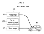
- the environmentally-friendly vehicle including the on-board charger is charged, as shown in FIG. 1 , in an electric vehicle charging station 10 .
- the electric vehicle charging station 10 as disclosed in the related art, may include a fast charger 11 , a slow charger 12 , and an electric vehicle charger 100 .
- the electric vehicle charger 100 may be configured to adjust the charging time of the respective chargers 11 and 12 to satisfy charging time requirements of various environmentally-friendly vehicles.
- a charging method is provided at a minimum cost by implementing a fee for charging power, and a usage fee for using the charging infrastructure, but the charging method cannot be usable at the charging station without the electric vehicle charging station 10 since the on-board charger installed in the vehicle does not adjust the charging.
- the electric vehicle charging station 10 in the related art is usable only when it is installed in each charging station, and therefore inconvenience and inefficiency are inevitable when using the electric vehicle charging station 10 .
- the battery charging energy is about ab.1 kWh (a, b): integer) when charged by the on-board charger with charging capacity of about x.6 kW (x is integer), but when the battery charging energy is about cd.9 kWh (c, d: integer, cd>ab), a user of the environmentally-friendly vehicle is required to pay a charge for cd.9 kWh, which is the energy used by the on-board charger.
- the present invention provides a slow charging method of an environmentally-friendly vehicle and an on-board charger using the same that may improve charging efficiency and thus save a charging cost by changing charging output of the on-board charger based on a temperature thereof.
- An exemplary embodiment of the present invention provides a slow charging method of an environmentally-friendly vehicle including an on-board charger, that may include: detecting a charging request; detecting a temperature of the on-board charger in response to detecting the charging request; determining whether the temperature of the on-board charger is within a predetermined temperature range; adjusting charging output of the on-board charger to a predetermined value when the temperature of the on-board charger is within the predetermined temperature range; and charging a battery of the environmentally-friendly vehicle with the adjusted charging output of the on-board charger.
- the adjusted charging output of the on-board charger may be less than the previous charging output of the on-board charger.
- the adjusted charging output of the on-board charger may be about 4.4 kW, and the previous charging output of the on-board charger may be about 6.6 kW.
- a charging time may be greater with the adjusted charging output of the on-board charger than a charging time with the previous charging output thereof.
- the charging output of the on-board charger may be maintained when the temperature of the on-board charger is beyond the predetermined temperature range.
- the temperature of the on-board charger may be detected at a predetermined time interval.
- An exemplary embodiment of the present invention provides an onboard charger of an environmentally-friendly vehicle, that may include: a temperature sensor configured to detect a temperature of the on-board charger; an output adjuster configured to adjust charging output of the on-board charger; and a controller configured to variably adjust the charging output of the on-board charger based on the temperature the on-board charger, wherein the controller may be configured to execute commands for performing the method described above.
- the charging output of the on-board charger may be adjusted, based on the temperature of the on-board charger, to improve the efficiency and reduce the charging cost.
- FIG. 1 is an exemplary diagram illustrating an electric vehicle charging station according to the related art
- FIG. 2 is an exemplary diagram illustrating an on-board charger of an environmentally-friendly vehicle according to an exemplary embodiment of the present invention
- FIG. 3 is an exemplary flowchart illustrating a slow charging method of the environmentally-friendly vehicle according to the exemplary embodiment of the present invention
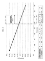
- FIG. 4 is an exemplary graph for describing the slow charging method of the environmentally-friendly vehicle and the on-board charger according to an exemplary embodiment of the present invention.
- FIGS. 5 and 6 are exemplary graphs/tables for describing the slow charging method of the environmentally-friendly vehicle according to an exemplary embodiment of the present invention.
- vehicle or “vehicular” or other similar term as used herein is inclusive of motor vehicles in general such as passenger automobiles including sports utility vehicles (SUV), buses, trucks, various commercial vehicles, watercraft including a variety of boats and ships, aircraft, and the like, and includes hybrid vehicles, electric vehicles, plug-in hybrid electric vehicles, hydrogen-powered vehicles and other alternative fuel vehicles (e.g. fuels derived from resources other than petroleum).
- a hybrid vehicle is a vehicle that has two or more sources of power, for example both gasoline-powered and electric-powered vehicles.
- controller/control unit refers to a hardware device that includes a memory and a processor.
- the memory is configured to store the modules and the processor is specifically configured to execute said modules to perform one or more processes which are described further below.
- control logic of the present invention may be embodied as non-transitory computer readable media on a computer readable medium containing executable program instructions executed by a processor, controller/control unit or the like.
- the computer readable mediums include, but are not limited to, ROM, RAM, compact disc (CD)-ROMs, magnetic tapes, floppy disks, flash drives, smart cards and optical data storage devices.
- the compute readable recording medium can also be distributed in network, coupled computer systems so that the computer readable media is stored and executed in a distributed fashion, e.g., by a telematics server or a Controller Area Network (CAN).
- a telematics server or a Controller Area Network (CAN).
- CAN Controller Area Network
- FIG. 2 is an exemplary diagram illustrating an on-board charger of an environmentally-friendly vehicle according to an exemplary embodiment of the present invention.
- An on-board charger of an environmentally-friendly vehicle according to an exemplary embodiment of the present invention refers to an on-board charger that may be configured to detect a temperature thereof and adjust charging output based on the detected temperature.
- the on-board charger 120 may include a temperature sensor 124 configured to detect temperature of the on-board charger 120 , an output adjuster 126 configured to adjust charging output of the on-board charger 120 , and a controller 122 configured to variably adjust the charging output of the on-board charger 120 based on the temperature thereof.
- the controller 122 may be configured to operate the temperature sensor 124 and the output adjuster 126 .
- the temperature sensor 124 may be installed within or extraneous to the on-board charger 120 as a sensor configured to detect the temperature of the on-board charger 120 (e.g., a coolant temperature of the on-board charger), but it should be understood that the scope of the present invention is not limited thereto. Even if the configurations are different from the above configuration, the technical spirit of the present invention may be applicable to any configuration that can substantially detect the temperature of the on-board charger 120 (a coolant temperature of the on-board charger).
- the output adjuster 126 may include an electronic power device configured to output or variably output the charging power.
- the controller 122 may be one or more microprocessors and/or hardware including a microprocessor that may be operated by a predetermined program, and the predetermined program may include a series of commands for executing the slow charging method to be described later according to the exemplary embodiment of the present invention.
- a slow charging method of an environmentally-friendly vehicle according to an exemplary embodiment of the present invention will now be described with reference to the drawings.
- FIG. 3 is an exemplary flowchart illustrating a slow charging method of the environmentally-friendly vehicle according to the exemplary embodiment of the present invention.
- a controller 122 may be configured to detect a charging request (S 110 ).
- the charging request may be generated when a charging plug (not shown) of a charging station is connected to a charging receptacle (not shown) of the environmentally-friendly vehicle.
- the controller 122 may be configured to detect a temperature sensed by a temperature sensor 124 (S 120 ).
- the temperature sensor 124 may be configured to detect a temperature of a coolant that cools the on-board charger 120 .
- the controller 122 upon detecting the charging request, the controller 122 ay be configured to determine the temperature sensed by the temperature sensor 124 at a predetermined time interval (e.g., 5 minutes, 10 minutes, etc.). The predetermined time interval may be changed depending on a design aspect.
- the controller 122 may be configured to determine whether the detected temperature of the on-board charger is within a predetermined temperature range (e.g., about 50° C. ⁇ 55° C.) (S 130 ).
- a predetermined temperature range e.g., about 50° C. ⁇ 55° C.
- the predetermined temperature range may be, as shown in FIGS. 4 to 6 , a coolant temperature range of the on-board charger 120 where charging efficiency and charging output of the on-board charger 120 are optimal.
- the on-board charger 120 may have optimal combination of the charging efficiency and charging output in the coolant temperature range of about 50° C. to 55° C.
- the controller 122 may be configured to operate the output adjuster 126 to adjust the charging output of the on-board charger 120 to a predetermined value (e.g., about 4.4 kW) (S 140 ).
- the predetermined value (e.g., about 4.4 kW) may be set to be less than the previous charging output of the on-board charger (e.g., about 6.6 kW) since, when the charging output is adjusted to the predetermined value, the charging time may increase but charging efficiency may also increase compared with that of the previous charging output (e.g., about 6.6 kW), thereby reducing charging cost.
- the charging cost is a more important factor than the charging time because the environmental)y-friendly vehicle is generally charged during the night (e.g., when the vehicle is not being driven for substantial periods of time).
- the output adjuster 126 may be configured to charge a battery 130 of the environmentally-friendly vehicle with the charging output of the on-board charger 120 adjusted by the controller 122 (S 140 ). Meanwhile, in the step S 130 , when the controller 122 determines that the temperature of the on-board charger 120 is out of the predetermined temperature range (e.g., beyond the predetermined temperature range), the controller may be configured to operate the output adjuster 126 to maintain the charging output of the on-board charger 120 at the current value, for example, at about 6.6 kW (S 135 ).
- a charging output change signal e.g., adjustment signal
- the charging output of the on-board charger may be adjusted based on the temperature thereof to improve the charging efficiency and to save the charging cost.
Landscapes
- Engineering & Computer Science (AREA)
- Power Engineering (AREA)
- Transportation (AREA)
- Mechanical Engineering (AREA)
- Life Sciences & Earth Sciences (AREA)
- Sustainable Development (AREA)
- Sustainable Energy (AREA)
- Charge And Discharge Circuits For Batteries Or The Like (AREA)
- Electric Propulsion And Braking For Vehicles (AREA)
Abstract
Description
Claims (12)
Applications Claiming Priority (2)
| Application Number | Priority Date | Filing Date | Title |
|---|---|---|---|
| KR1020140044238A KR101610102B1 (en) | 2014-04-14 | 2014-04-14 | Slow charge method and on-board charger for environmentally-friendly vehicle |
| KR10-2014-0044238 | 2014-04-14 |
Publications (2)
| Publication Number | Publication Date |
|---|---|
| US20150291043A1 US20150291043A1 (en) | 2015-10-15 |
| US9610855B2 true US9610855B2 (en) | 2017-04-04 |
Family
ID=54264395
Family Applications (1)
| Application Number | Title | Priority Date | Filing Date |
|---|---|---|---|
| US14/470,142 Active 2035-05-02 US9610855B2 (en) | 2014-04-14 | 2014-08-27 | Slow charging method and on-board charger for environmentally-friendly vehicle using the same |
Country Status (3)
| Country | Link |
|---|---|
| US (1) | US9610855B2 (en) |
| KR (1) | KR101610102B1 (en) |
| CN (1) | CN104979596B (en) |
Families Citing this family (10)
| Publication number | Priority date | Publication date | Assignee | Title |
|---|---|---|---|---|
| US9804034B2 (en) * | 2014-11-14 | 2017-10-31 | Schneider Electric USA, Inc. | EVSE with cordset handle temperature measurement |
| US9707850B2 (en) | 2014-11-18 | 2017-07-18 | Schneider Electric USA, Inc. | EVSE handle with automatic thermal shut down by NTC to ground |
| KR101798514B1 (en) * | 2015-11-09 | 2017-11-16 | 현대자동차주식회사 | Vehicle and method of recharging battery therein |
| KR102388149B1 (en) * | 2017-06-08 | 2022-04-19 | 현대자동차주식회사 | Plug-in vehicle and method of controlling thereof |
| CN109849719B (en) * | 2018-12-14 | 2021-03-16 | 珠海格力电器股份有限公司 | Charging station of integrated refrigeration system and control method thereof |
| KR20200110901A (en) * | 2019-03-18 | 2020-09-28 | 현대자동차주식회사 | Cooling control system and method for on board charger of plug-in vehicle |
| KR102717297B1 (en) * | 2019-10-08 | 2024-10-16 | 현대자동차주식회사 | Battery charger for electric vehicle |
| CN112461402A (en) * | 2020-12-08 | 2021-03-09 | 台达电子企业管理(上海)有限公司 | Temperature detection system and vehicle-mounted charger |
| CN114374307B (en) * | 2021-04-30 | 2024-06-11 | 华为数字能源技术有限公司 | Temperature protection method and device for vehicle charger, and vehicle charger |
| KR102627312B1 (en) * | 2023-09-22 | 2024-01-19 | 제룡전기 주식회사 | Electric vehicle charger mounted transformer |
Citations (7)
| Publication number | Priority date | Publication date | Assignee | Title |
|---|---|---|---|---|
| KR940012745A (en) | 1992-11-19 | 1994-06-24 | 정용문 | Battery charging device and method |
| KR970066432A (en) | 1996-03-21 | 1997-10-13 | 배순훈 | Temperature detection method |
| US20100156355A1 (en) * | 2008-12-19 | 2010-06-24 | Gm Global Technology Operations, Inc. | System and method for charging a plug-in electric vehicle |
| JP2012091728A (en) | 2010-10-28 | 2012-05-17 | Daimler Ag | Plug-in hybrid electric vehicle and control method thereof |
| KR20120102308A (en) | 2011-03-08 | 2012-09-18 | 주식회사 만도 | Apparatus to charge battery voltage for electric vehicle |
| KR20130032493A (en) | 2011-09-23 | 2013-04-02 | 한국전력공사 | Apparatus and method for charging of electric vehicle |
| JP2013067247A (en) | 2011-09-21 | 2013-04-18 | Nippon Soken Inc | Charging apparatus for vehicle |
-
2014
- 2014-04-14 KR KR1020140044238A patent/KR101610102B1/en active Active
- 2014-08-27 US US14/470,142 patent/US9610855B2/en active Active
- 2014-09-19 CN CN201410483103.8A patent/CN104979596B/en active Active
Patent Citations (7)
| Publication number | Priority date | Publication date | Assignee | Title |
|---|---|---|---|---|
| KR940012745A (en) | 1992-11-19 | 1994-06-24 | 정용문 | Battery charging device and method |
| KR970066432A (en) | 1996-03-21 | 1997-10-13 | 배순훈 | Temperature detection method |
| US20100156355A1 (en) * | 2008-12-19 | 2010-06-24 | Gm Global Technology Operations, Inc. | System and method for charging a plug-in electric vehicle |
| JP2012091728A (en) | 2010-10-28 | 2012-05-17 | Daimler Ag | Plug-in hybrid electric vehicle and control method thereof |
| KR20120102308A (en) | 2011-03-08 | 2012-09-18 | 주식회사 만도 | Apparatus to charge battery voltage for electric vehicle |
| JP2013067247A (en) | 2011-09-21 | 2013-04-18 | Nippon Soken Inc | Charging apparatus for vehicle |
| KR20130032493A (en) | 2011-09-23 | 2013-04-02 | 한국전력공사 | Apparatus and method for charging of electric vehicle |
Also Published As
| Publication number | Publication date |
|---|---|
| KR20150118407A (en) | 2015-10-22 |
| CN104979596B (en) | 2019-09-20 |
| US20150291043A1 (en) | 2015-10-15 |
| CN104979596A (en) | 2015-10-14 |
| KR101610102B1 (en) | 2016-04-08 |
Similar Documents
| Publication | Publication Date | Title |
|---|---|---|
| US9610855B2 (en) | Slow charging method and on-board charger for environmentally-friendly vehicle using the same | |
| US9463710B2 (en) | System and method of balancing battery cell | |
| US9667081B2 (en) | Battery charging system using charger and driving control method of the charger thereof | |
| US9352664B2 (en) | Charging control method and system for environmentally friendly vehicle | |
| US9283861B2 (en) | On-board battery charger for electric vehicles and control method thereof | |
| US10513200B2 (en) | Vehicle battery system and method of controlling charge of battery in the system | |
| CN104734274B (en) | Vehicle battery charging equipment and the method for using vehicle battery charging equipment | |
| US9484804B2 (en) | Battery charging system and method | |
| US9180785B2 (en) | System and method of controlling low-voltage DC/DC converter for electric vehicle | |
| US20160137080A1 (en) | Apparatus and method for charging battery for vehicle | |
| US9632118B2 (en) | Current sensing device and method using current transformer | |
| US20160016480A1 (en) | Method and system for controlling electric vehicles | |
| US20150180255A1 (en) | Method and system of calculating battery charge time | |
| US10899244B2 (en) | Charging control method with use of a power factor correction circuit and system for electric vehicle | |
| US10493857B2 (en) | Method and system for controlling charging device for vehicles | |
| US20170001534A1 (en) | Device and method for controlling battery charge and discharge quantity in eco-friendly vehicle | |
| CN104467060A (en) | Charging system and method of battery | |
| US11135926B2 (en) | System and method for controlling charging of plug-in vehicle | |
| US10293701B2 (en) | Control method and system of low-voltage DC-DC converter for hybrid vehicle | |
| US9656557B2 (en) | Battery charging apparatus and method of electric vehicle | |
| US9669728B2 (en) | System and method for controlling LDC of hybrid vehicle | |
| US20170101020A1 (en) | Method and system of operating on-board charger for eco-friendly vehicle | |
| US10923937B2 (en) | Charging system for eco-friendly vehicle and charge control method using the same | |
| US11207992B2 (en) | Power conversion system for vehicles and control method thereof | |
| US10063150B2 (en) | Method and system of controlling converter |
Legal Events
| Date | Code | Title | Description |
|---|---|---|---|
| AS | Assignment |
Owner name: HYUNDAI MOTOR COMPANY, KOREA, REPUBLIC OF Free format text: ASSIGNMENT OF ASSIGNORS INTEREST;ASSIGNORS:NAM, HOUK;YANG, CHAE MO;REEL/FRAME:033621/0142 Effective date: 20140728 |
|
| FEPP | Fee payment procedure |
Free format text: PAYOR NUMBER ASSIGNED (ORIGINAL EVENT CODE: ASPN); ENTITY STATUS OF PATENT OWNER: LARGE ENTITY Free format text: PAYER NUMBER DE-ASSIGNED (ORIGINAL EVENT CODE: RMPN); ENTITY STATUS OF PATENT OWNER: LARGE ENTITY |
|
| STCF | Information on status: patent grant |
Free format text: PATENTED CASE |
|
| MAFP | Maintenance fee payment |
Free format text: PAYMENT OF MAINTENANCE FEE, 4TH YEAR, LARGE ENTITY (ORIGINAL EVENT CODE: M1551); ENTITY STATUS OF PATENT OWNER: LARGE ENTITY Year of fee payment: 4 |
|
| MAFP | Maintenance fee payment |
Free format text: PAYMENT OF MAINTENANCE FEE, 8TH YEAR, LARGE ENTITY (ORIGINAL EVENT CODE: M1552); ENTITY STATUS OF PATENT OWNER: LARGE ENTITY Year of fee payment: 8 |