US9599042B2 - Start of injection timing - Google Patents
Start of injection timing Download PDFInfo
- Publication number
- US9599042B2 US9599042B2 US13/882,341 US201013882341A US9599042B2 US 9599042 B2 US9599042 B2 US 9599042B2 US 201013882341 A US201013882341 A US 201013882341A US 9599042 B2 US9599042 B2 US 9599042B2
- Authority
- US
- United States
- Prior art keywords
- intake manifold
- oxygen concentration
- manifold pressure
- steady state
- multiplier
- Prior art date
- Legal status (The legal status is an assumption and is not a legal conclusion. Google has not performed a legal analysis and makes no representation as to the accuracy of the status listed.)
- Active, expires
Links
Images


Classifications
-
- F—MECHANICAL ENGINEERING; LIGHTING; HEATING; WEAPONS; BLASTING
- F02—COMBUSTION ENGINES; HOT-GAS OR COMBUSTION-PRODUCT ENGINE PLANTS
- F02D—CONTROLLING COMBUSTION ENGINES
- F02D41/00—Electrical control of supply of combustible mixture or its constituents
-
- F—MECHANICAL ENGINEERING; LIGHTING; HEATING; WEAPONS; BLASTING
- F02—COMBUSTION ENGINES; HOT-GAS OR COMBUSTION-PRODUCT ENGINE PLANTS
- F02D—CONTROLLING COMBUSTION ENGINES
- F02D41/00—Electrical control of supply of combustible mixture or its constituents
- F02D41/30—Controlling fuel injection
- F02D41/38—Controlling fuel injection of the high pressure type
- F02D41/40—Controlling fuel injection of the high pressure type with means for controlling injection timing or duration
- F02D41/401—Controlling injection timing
-
- F—MECHANICAL ENGINEERING; LIGHTING; HEATING; WEAPONS; BLASTING
- F02—COMBUSTION ENGINES; HOT-GAS OR COMBUSTION-PRODUCT ENGINE PLANTS
- F02D—CONTROLLING COMBUSTION ENGINES
- F02D2200/00—Input parameters for engine control
- F02D2200/02—Input parameters for engine control the parameters being related to the engine
- F02D2200/04—Engine intake system parameters
- F02D2200/0406—Intake manifold pressure
-
- F—MECHANICAL ENGINEERING; LIGHTING; HEATING; WEAPONS; BLASTING
- F02—COMBUSTION ENGINES; HOT-GAS OR COMBUSTION-PRODUCT ENGINE PLANTS
- F02D—CONTROLLING COMBUSTION ENGINES
- F02D41/00—Electrical control of supply of combustible mixture or its constituents
- F02D41/02—Circuit arrangements for generating control signals
- F02D41/14—Introducing closed-loop corrections
- F02D41/1438—Introducing closed-loop corrections using means for determining characteristics of the combustion gases; Sensors therefor
- F02D41/1439—Introducing closed-loop corrections using means for determining characteristics of the combustion gases; Sensors therefor characterised by the position of the sensor
- F02D41/144—Sensor in intake manifold
-
- F—MECHANICAL ENGINEERING; LIGHTING; HEATING; WEAPONS; BLASTING
- F02—COMBUSTION ENGINES; HOT-GAS OR COMBUSTION-PRODUCT ENGINE PLANTS
- F02D—CONTROLLING COMBUSTION ENGINES
- F02D41/00—Electrical control of supply of combustible mixture or its constituents
- F02D41/02—Circuit arrangements for generating control signals
- F02D41/14—Introducing closed-loop corrections
- F02D41/1438—Introducing closed-loop corrections using means for determining characteristics of the combustion gases; Sensors therefor
- F02D41/1444—Introducing closed-loop corrections using means for determining characteristics of the combustion gases; Sensors therefor characterised by the characteristics of the combustion gases
- F02D41/1454—Introducing closed-loop corrections using means for determining characteristics of the combustion gases; Sensors therefor characterised by the characteristics of the combustion gases the characteristics being an oxygen content or concentration or the air-fuel ratio
-
- Y—GENERAL TAGGING OF NEW TECHNOLOGICAL DEVELOPMENTS; GENERAL TAGGING OF CROSS-SECTIONAL TECHNOLOGIES SPANNING OVER SEVERAL SECTIONS OF THE IPC; TECHNICAL SUBJECTS COVERED BY FORMER USPC CROSS-REFERENCE ART COLLECTIONS [XRACs] AND DIGESTS
- Y02—TECHNOLOGIES OR APPLICATIONS FOR MITIGATION OR ADAPTATION AGAINST CLIMATE CHANGE
- Y02T—CLIMATE CHANGE MITIGATION TECHNOLOGIES RELATED TO TRANSPORTATION
- Y02T10/00—Road transport of goods or passengers
- Y02T10/10—Internal combustion engine [ICE] based vehicles
- Y02T10/40—Engine management systems
-
- Y02T10/44—
Definitions
- This invention relates to internal combustion engines, including but not limited to the timing of fuel injection.
- the fuel injector is a nozzle which injects fuel, atomized by forcibly pumping fuel through the nozzle at high pressure, directly into the combustion chamber of each cylinder.
- a fuel injector, particularly a fuel injector for use with a diesel engine, is required to accurately discharge a quantity of fuel into a combustion chamber of an internal combustion engine over a wide range of engine operating conditions.
- Fuel is injected into the combustion chamber during the final stage of compression.
- the high degree of compression heats the air such that the heat initiates combustion of the fuel when the fuel is injected into the chamber.
- the fuel injector ensures that fuel is injected in fine droplets to allow for even distribution, which enhances efficiency of the combustion process and results in improved engine performance.
- the start of injection is determined by the fuel injection timing of the fuel system, often controlled by an engine control unit (ECU).
- SOI timing is an important factor in lowering emissions and improving engine efficiency. Timing of the SOI is measured in degrees of the crank angle of the piston before top dead center (BTDC), which is the highest position the piston reaches in the cylinder.
- BTDC top dead center
- the ECU receives input on engine operating conditions such as the engine speed, indicated torque, intake manifold pressure, oxygen concentration, and fuel temperature. Based on the engine operating conditions, the ECU determines an optimal SOI time to maximize power and efficiency while minimizing emissions.
- EGR exhaust gas recirculation
- the present inventors have recognized that SOI timing can be derived from correlations of ignition delay and information based on steady state engine operating conditions which are readily achieved in an experimental setting. Because the engine is often subject to conditions when ideal correlations cannot be maintained, timing SOI during transient operating conditions based on an ignition delay correlation can optimize engine performance.
- the present inventors have recognized the need for a method of improving injection timing control to decrease engine misfire, and to avoid excessively advanced combustion.
- the present inventors have recognized the need for an engine management system that enables the operation of an engine with high levels of EGR and late combustion timings while containing misfiring events.
- the present inventors have recognized that SOI compensation based on ignition delay correlation can contain combustion phasing under transient operating conditions.
- an engine management system for controlling start of injection (SOI) timing adjusts SOI based on steady state reference values to maintain a targeted combustion phasing (CA 50 ) despite intake manifold conditions significantly different from calibrated values due to transient operating conditions, and other operating variabilities.
- SOI start of injection
- a method for controlling SOI for an engine having an engine management system based on correlations of ignition delay comprises the steps of: acquiring a measurement of, or an estimate of, intake manifold pressure (MAP), acquiring a measurement of, or an estimate of, intake manifold oxygen concentration (X O2 ), comparing the intake manifold pressure (MAP) and the intake oxygen concentration (X O2 ) to steady state reference tabulated values (MAP ss and X O2,ss ), and prescribing a compensated SOI timing based on reference tabulated ignition delay values.
- MAP intake manifold pressure
- X O2 intake manifold oxygen concentration
- the steps of acquiring intake manifold pressure and acquiring intake manifold oxygen concentration are accomplished through direct or indirect measuring techniques.
- Direct techniques such as the use of an oxygen or pressure sensor, or indirect techniques such as the use of theoretical calculations known to one skilled in the art, can be used.
- Intake manifold pressure at transient conditions is compared to steady state intake manifold pressure by taking the ratio of the two values (MAP/MAP ss ) to determine the intake manifold pressure compensation factor.
- the intake manifold pressure compensation factor represents the MAP value relative to the steady state MAP reference value (MAP ss ).
- the intake manifold pressure compensation factor is raised exponentially to a power of intake manifold pressure exponential factor to determine the intake manifold pressure multiplier.
- the intake manifold oxygen concentration at transient conditions is compared to steady state intake manifold oxygen concentration by taking the ratio of the two values (X o2 /X o2ss ) to determine the oxygen concentration compensation factor.
- the oxygen concentration factor is raised exponentially to the power of an oxygen concentration exponential factor to determine the oxygen concentration multiplier.
- an ignition delay crank angle ratio is correlated to the product of the intake manifold pressure multiplier and the oxygen concentration multiplier according to the following equation:
- the crank angle ratio is obtained by taking the ratio of the difference between a reference combustion phasing crank angle at steady state (CA 50 ss ) and the SOI at transient conditions (SOI) to the difference between the reference combustion phasing crank angle at steady state (CA 50 ss ) and the SOI at steady state conditions (SOI ss ).
- the reference combustion phasing crank angle is preferably the crank angle at which 50% of maximum fuel burning occurs in the combustion chamber under steady state conditions (CA 50 ss ).
- FIG. 1 is a schematic diagram of an engine system that includes a turbocharger in accordance with an exemplary embodiment of the invention.
- FIG. 1A is a schematic diagram of a dual stage turbocharger engine system that comprises a high pressure EGR loop.
- FIG. 2 is a schematic diagram of a cylinder in an internal combustion engine.
- FIG. 3 is a schematic diagram illustrating informational inputs into the engine control unit.
- FIG. 4 is a flow diagram illustrating an exemplary embodiment of a method for compensating SOI based on ignition delay correlation.
- FIG. 5A illustrates sample transient engine speed and load conditions.
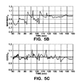
- FIG. 5B illustrates intake manifold pressure (MAP) normalized by calibrated steady-state values.
- FIG. 5C illustrates estimated intake manifold oxygen concentration (X O2 )
- FIG. 5D illustrates a comparison of start of injection with and without ignition delay compensation.
- FIG. 5E compares combustion phasing (CA 50 ) using start of injection strategy with and without ignition delay compensation.
- the engine 100 has a block 101 that includes a plurality of cylinders.
- the cylinders in the block 101 are fluidly connected to an intake system 103 and to an exhaust system 105 .
- the exhaust system includes a first pipe 105 a from cylinders 1 , 2 and 3 of one bank of cylinders and a second pipe 105 b from cylinders 4 , 5 and 6 .
- an inline arrangement of six cylinders is illustrated, inline or V-arrangements or other arrangements of plural cylinders of any number of cylinders are also encompassed by the invention.
- a turbocharger 107 includes a turbine 109 .
- the turbine 109 shown has a single turbine inlet port 113 connected to the exhaust system 105 .
- the turbocharger 107 includes a compressor 111 connected to the intake system 103 through an inlet air passage 115 .
- air may enter the compressor 111 through an air inlet 117 .
- Compressed air may exit the compressor 111 through a discharge nozzle 207 , pass through the inlet air passage 115 , and pass through an optional charge air cooler 119 and an optional inlet throttle 120 before entering an intake air mixer 121 and an intake air manifold 122 of the intake system 103 .
- the compressed air enters the engine cylinders 1 - 6 .
- a stream of exhaust gas from the exhaust system 105 may be routed through an EGR passage or conduit 124 , through an exhaust gas recirculation (EGR) valve 125 , through an exhaust gas recirculation (EGR) cooler 126 and pass through a further EGR conduit 127 before meeting and mixing with air from the inlet throttle 120 at the mixer 121 .
- EGR exhaust gas recirculation
- EGR exhaust gas recirculation
- the inlet port 113 of the turbine 109 may be connected to the exhaust pipes 105 a , 105 b in a manner that forms a divided exhaust manifold 129 . Exhaust gas passing through the turbine 109 may exit the engine 100 through a tailpipe 134 . Emissions and sound treating components can be arranged to receive the exhaust gas from the tailpipe, before exhausting to atmosphere, as is known.
- FIG. 1A illustrates an engine comprising two turbochargers, a high pressure turbocharger 208 , and a low pressure turbocharger 209 , as well as a high pressure EGR loop 211 .
- a cylinder 210 in an internal combustion engine is illustrated in FIG. 2 .
- a piston 220 in the cylinder reciprocates and defines engine strokes.
- a combustion chamber 230 is defined by the cylinder head above the piston and within the cylinder 210 .
- the piston 220 is connected by a connecting rod 240 to a crankshaft 250 , which in turn is connected to a drive chain 295 which drives a cam shaft 280 .
- the cam shaft 280 drives a cam 290 .
- Inlet valve 260 and exhaust valve 270 are disposed on top of the cylinder 210 , and are driven in a timed relationship to the movement of the piston 220 .
- Inlet valve 260 and exhaust valve 270 are connected to rocker arms 200 , which are each in contact with a cam 290 (not shown for inlet valve 270 ).
- the opening and closing of the valves 260 , 270 is controlled by the movement of the rocker arm 200 . Because the rocker arm is in connection with the piston via the cam 290 , cam shaft 280 , crankshaft 250 and connecting rod 240 , the opening and closing of the valves 260 , 270 is dependent on the movement of the piston 220 , and can be timed relative to the movement of the piston 220 .
- the internal combustion engine of FIG. 2 comprises a fuel injection system.
- the fuel injection system comprises a fuel injector 205 , held in place on the top of the cylinder 210 by a clamping mechanism 206 .
- the fuel injector 205 injects atomized fuel into the combustion chamber 230 .
- An engine management system comprising an engine control unit (ECU) 400 ( FIG. 3 ) controls the timing and amount of fuel that is injected into the combustion chamber 230 .
- Start of injection is measured in degrees of the crank angle of the piston relative to the top dead center position of the piston.
- Start of injection (SOI) occurs during a certain crank angle, such as, for example 30 degrees before top dead center (BTDC).
- the SOI is initiated by the ECU 400 .
- the ECU compensates for SOI timing under transient operating conditions using physical information available through an estimate of intake manifold conditions and engine operating conditions.
- Information on intake manifold conditions such as manifold pressure 540 and oxygen concentration 570 , as well as information on engine operating conditions such as indicated torque set-point 500 and engine speed 510 , are transmitted to the ECU 400 for processing as illustrated in FIG. 3 .
- the ECU 400 calculates, based on the information it receives, the optimal timing for SOI 700 under the set of engine operating conditions to maintain target combustion phasing (CA 50 ) in order to avoid misfire and the NOx penalty associated with overly advanced combustion phasing.
- CA 50 target combustion phasing
- T a is average temperature
- This method of SOI compensation is based on known correlations of ignition delay, such as those expressed by the above Equation 1. or Equation 2., and detailed information on experiments in research engines often obtained under ideal conditions which optimize the fuel/air mixture. In operation, the engine is often subjected to conditions where such ideal conditions cannot be maintained, thus absolute values for ignition delay will not hold. However, information gained from steady-state, ideal operating conditions can serve as a reference for determining SOI timing. As illustrated by the equation above, it is the ratio of ignition delay that is correlated to intake manifold pressure and oxygen concentration.
- Ignition delay refers to the time period between the beginning or end of injection, and a time point in the combustion process, such as the beginning of combustion.
- Intake manifold conditions such as intake manifold pressure (MAP), and oxygen concentration (X O2 ) are some of the parameters for which ignition delay correlation data can be collected for a particular engine. Because ignition delay is dependent on the air/fuel mixture ratio, parameters such as pressure and oxygen concentration which proscribe how much air enters the cylinder, play an important role.
- the ignition delay is measured between the injection and point during the combustion process wherein 50% of the fuel has been used for combustion.
- Ignition delay values can be obtained for steady state (SS) reference values of intake manifold pressure (MAP ss ), oxygen concentration (X O2ss ), baseline start of injection (SOI ss ) and combustion phasing (CA 50 ss ) for a particular engine or engine type by subjecting the engine to steady state operating conditions at a desired torque strength and engine speed and gathering experimental data for correlation.
- SS steady state
- MAP ss intake manifold pressure
- X O2ss oxygen concentration
- SOI ss baseline start of injection
- CA 50 ss combustion phasing
- Combustion phasing tracks the beginning to the end of combustion process by determining the intensity of heat release, which is indicative of the combustion process. Combustion phasing is expressed by the crank angle at which a certain amount of fuel has been burnt. CA 50 ss is the crank angle at which 50% of the fuel is burnt under steady state ideal condition. Other crank angles may be used with other ignition delay correlation equations.
- an optimal time for SOI at transient operating conditions to reach target combustion phasing is determined according to the flow chart illustrated in FIG. 4 .
- the ECU (not shown in FIG. 4 ) processes information pertaining to manifold pressure 540 , oxygen concentration 570 , indicated torque set-point 500 , and engine speed 510 according to the flow chart to determine the crank angle at which fuel injection should begin.
- the flow chart illustrates the steps required to generate the SOI command sent out by the ECU according to the following equation:
- the ECU 400 receives input on engine operating conditions, particularly an indicated torque set-point 500 and engine speed signal 510 .
- engine operating conditions particularly an indicated torque set-point 500 and engine speed signal 510 .
- CA 50 ss the crank angle at which 50% fuel is burnt at steady state conditions
- CA 50 ss a correction can be made at step 521 based on dynamic situations or misfires, represented as input 522 .
- CA 50 ss will be equal to CA 50 sp .
- Indicated torque is essentially the useful torque being produced by the engine, corresponding to the torque at the clutch for propelling the vehicle plus torques used for other purposes such as operating a torque converter and engine-driven accessories like alternators and fuel pumps, and overcoming engine rotating friction.
- the indicated torque set-point is derived by observing the fuel quantity injected for torque generation along with engine speed. Therefore, the indicated torque set-point is tabulated in a two-dimensional table with inputs of engine speed and fuel quantity injected for torque generation. Methods used for linking accelerator pedal position, injected fuel quantity for torque, and indicated torque set-point are known to one of skill in the art.
- Engine speed is measured in known fashion such as by using a proximity sensor adjacent to a flywheel.
- the SOI ss reference value based on steady state experimental testing are also identified at step 530 based on the indicated torque set-point 500 and engine speed signal 510 .
- the MAP ss reference value based on steady state experimental testing are also identified at step 560 based on the indicated torque set-point 500 and engine speed signal 510 .
- the X O2ss reference value based on steady state experimental testing are also identified at step 590 based on the indicated torque set-point 500 and engine speed signal 510 .
- the flow chart illustrates that at a particular indicated torque set-point 500 and engine speed signal 510 , combustion phasing angle—in this case CA 50 ss , and SOI ss reference values at steady state is retrieved by the ECU for use in determining the SOI timing.
- a MAP value 540 under transient operating conditions is obtained for comparison at step 550 with reference values for MAP ss from step 560 at a particular indicated torque set-point 500 and engine speed signal 510 .
- FIG. 5A illustrates a sample of speed and torque profiles for an engine operating under transient conditions as a function of time.
- FIG. 5B compares estimates of intake manifold pressure (MAP) with steady-state tabulated values (MAP ss ) for an engine operating under transient conditions as a function of time. Ratios below a value of 1 signify intake manifold pressures lower than the reference values, while ratios above 1 signify that intake manifold pressure (MAP) is above reference values.
- an oxygen concentration value (X O2 ) 570 for the engine under transient operating conditions is obtained for comparison at step 580 to reference values for oxygen concentration at steady state (X O2ss ) step 590 for a particular indicated torque set-point 500 and engine speed signal 510 .
- FIG. 5C compares estimates of intake oxygen concentration (X O2 ) with steady-state tabulated values (X O2ss ) for an engine operating under transient conditions as a function of time. Ratios below a value of 1 signify oxygen concentration lower than reference values, while ratios above 1 signify oxygen concentrations higher than reference values.
- the step 550 of comparing the MAP to MAP ss , and the step 580 of comparing X O2 to X O2ss comprise taking the ratios of the MAP and X O2 to the MAP ss and X O2ss , respectively.
- the ratio of MAP/MAP ss is the intake manifold pressure compensation factor “U”
- the ratio of X O2 /X O2ss is the oxygen concentration factor “S”.
- the intake manifold pressure compensation factor U is raised exponentially to an intake manifold pressure compensation exponential factor “v” at an intake manifold pressure multiplier step 600 .
- the oxygen concentration factor S is raised exponentially to an oxygen concentration exponential factor “t” at an oxygen concentration multiplier step 610 .
- the intake manifold pressure compensation exponential factor v and the oxygen concentration exponential factor t are experimentally derived inputs 620 , 630 for a particular engine or for engine types with similar characteristics. Data points are collected for a particular engine or engine type, wherein a best fit curve is generated and the exponential factors are derived as known to one skilled in the art.
- the intake manifold pressure compensation exponential factor v is ⁇ 0.7 and the oxygen concentration exponential factor t is ⁇ 1.2.
- the MAP signal 540 is an estimate of the intake manifold pressure, or a direct measurement of the intake manifold pressure, such as by using a pressure sensor.
- the X O2 signal 570 is an estimate the intake manifold oxygen concentration, or a direct measurement of intake manifold oxygen concentration, such as by using an oxygen sensor.
- the SOI determined in step 530 is subtracted from the steady state crank angle CA 50 ss determined in step 520 (CA 50 ss ⁇ SOI ss ) at a step 730 .
- the difference (CA 50 ss ⁇ SOI ss ) calculated at step 730 is multiplied by the intake manifold pressure multiplier and the intake oxygen concentration multiplier calculated in steps 600 , 610 .
- the resulting value from step 710 can then be subtracted in a step 720 from the CA 50 ss value determined from step 520 to issue an SOI command step 700 sent to the fuel injector to begin fuel injection at the appropriate timing.
- FIG. 5D compares reference SOI values with SOI based on ignition delay compensation for an engine operating under transient conditions as a function of time.
- FIG. 5E compares combustion phasing of SOI strategies with and without ignition delay compensation to target combustion phasing for an engine operating under transient conditions as a function of time.
- FIG. 5E illustrates that the SOI compensation based on ignition delay correlation is able to maintain combustion phasing during a selected portion of a transient cycle by adjusting the SOI.
- Combustion phasing (CA 50 ) ahead of the targeted values result in a NO x penalty, while excessively retarded phasing risks misfire due to decreased stability.
- CA 50 using SOI based on ignition delay follows target combustion phasing more closely than CA 50 using steady-state reference values.
- the ECU receives input regarding the indicated torque, the engine speed, MAP measurement or estimate and the O2 measurement or estimate.
- indicated torque and engine speed steady state values for desired combustion phasing, CA 50 ss, steady state values for SOI-SOIss, steady state values for MAP-MAP ss , and steady state values for oxygen concentration XO2 are used as a reference.
- the MAP value and the O2 value at transient conditions are supplied to the ECU to perform calculations according to the SOI compensation equation above (Equation 3.) to arrive at an optimal SOI under occurring transient operating conditions.
- the SOI can accordingly be determined.
Landscapes
- Engineering & Computer Science (AREA)
- Chemical & Material Sciences (AREA)
- Combustion & Propulsion (AREA)
- Mechanical Engineering (AREA)
- General Engineering & Computer Science (AREA)
- Electrical Control Of Air Or Fuel Supplied To Internal-Combustion Engine (AREA)
- Combined Controls Of Internal Combustion Engines (AREA)
Abstract
Description
- Where t is in microseconds,
- A and n are adjustable constants,
- p is ambient pressure,
- EA is activation energy,
- R is the universal gas constant, and
- T is temperature.
τ=12.254·
-
- 100 engine
- 101 block
- 103 intake system
- 105 exhaust system
- 105 a first exhaust pipe
- 105 b second exhaust pipe
- 107 turbocharger
- 109 turbine
- 111 compressor
- 113 inlet port
- 115 inlet air passage
- 117 air inlet
- 119 optional charge air cooler
- 120 optional inlet throttle
- 121 inlet air mixer
- 122 intake manifold
- 124 EGR conduit
- 125 EGR valve
- 126 exhaust gas recirculation cooler
- 127 conduit
- 129 divided exhaust manifold
- 134 tailpipe
- 200 rocker arm
- 205 fuel injector
- 206 clamping mechanism
- 207 discharge nozzle
- 208 high pressure turbocharger
- 209 low pressure turbocharger
- 210 cylinder
- 211 high pressure EGR loop
- 220 piston
- 230 combustion chamber
- 240 connecting rod
- 250 crankshaft
- 260 valve
- 270 valve
- 280 cam shaft
- 290 cam
- 295 drive chain
- 400 engine control unit
- 500 indicated torque set-point
- 510 engine speed signal
- 520 step of determining CA50 ss steady state crank angle
- 521 step of determining CA50 sp
- 522 input to step 521
- 530 step of determining SOIss start of ignition
- 540 manifold pressure
- 550 comparison of MAP to MAPss
- 560 step of determining MAPss
- 570 step of determining oxygen concentration
- 580 step of comparison of XO2 to XO2,SS
- 590 step of determining XO2ss
- 600 intake manifold pressure multiplier step
- 610 oxygen concentration multiplier step
- 620 intake manifold pressure compensation exponential factor
- 630 oxygen concentration exponential factor
- 700 Start Of Injection Command
- 710 step of multiplying (CA50 ss−SOIss) with the intake manifold pressure multiplier and the intake oxygen concentration multiplier
- 720 step of subtracting value resulting from 710, from CA50 sp
- 730 step of subtracting SOIss from CA50 ss
Claims (17)
Applications Claiming Priority (1)
| Application Number | Priority Date | Filing Date | Title |
|---|---|---|---|
| PCT/US2010/054387 WO2012057756A1 (en) | 2010-10-28 | 2010-10-28 | Start of injection timing |
Publications (2)
| Publication Number | Publication Date |
|---|---|
| US20130213352A1 US20130213352A1 (en) | 2013-08-22 |
| US9599042B2 true US9599042B2 (en) | 2017-03-21 |
Family
ID=45994227
Family Applications (1)
| Application Number | Title | Priority Date | Filing Date |
|---|---|---|---|
| US13/882,341 Active 2032-11-30 US9599042B2 (en) | 2010-10-28 | 2010-10-28 | Start of injection timing |
Country Status (2)
| Country | Link |
|---|---|
| US (1) | US9599042B2 (en) |
| WO (1) | WO2012057756A1 (en) |
Families Citing this family (7)
| Publication number | Priority date | Publication date | Assignee | Title |
|---|---|---|---|---|
| US10066564B2 (en) | 2012-06-07 | 2018-09-04 | GM Global Technology Operations LLC | Humidity determination and compensation systems and methods using an intake oxygen sensor |
| US9631567B2 (en) * | 2013-08-15 | 2017-04-25 | GM Global Technology Operations LLC | Sensor based measurement and purge control of fuel vapors in internal combustion engines |
| DE102015201905A1 (en) * | 2015-02-04 | 2016-08-04 | Robert Bosch Gmbh | Method for reducing exhaust emissions in a transient transition phase of a vehicle |
| JP6213525B2 (en) * | 2015-06-18 | 2017-10-18 | トヨタ自動車株式会社 | Control device for internal combustion engine |
| US10718286B2 (en) * | 2016-08-23 | 2020-07-21 | Ford Global Technologies, Llc | System and method for controlling fuel supplied to an engine |
| JP6755167B2 (en) | 2016-12-05 | 2020-09-16 | いすゞ自動車株式会社 | Control device |
| CN109322751A (en) * | 2018-10-09 | 2019-02-12 | 广西玉柴机器股份有限公司 | The gas engine of adaptive methane concentration variation starts control method |
Citations (4)
| Publication number | Priority date | Publication date | Assignee | Title |
|---|---|---|---|---|
| US20020029768A1 (en) * | 2000-09-08 | 2002-03-14 | Takuji Matsubara | Fuel injection control apparatus and method of direct fuel injection-type spark ignition engine |
| US20070174003A1 (en) * | 2006-01-20 | 2007-07-26 | Honda Motor Co., Ltd. | Control system for internal combustion engine |
| US20090306877A1 (en) * | 2008-06-06 | 2009-12-10 | Southwest Research Insititute | Combustion control system for internal combustion engine with rich and lean operating conditions |
| US8538657B2 (en) * | 2009-04-30 | 2013-09-17 | General Electric Company | Systems and methods for controlling fuel flow to a turbine component |
-
2010
- 2010-10-28 US US13/882,341 patent/US9599042B2/en active Active
- 2010-10-28 WO PCT/US2010/054387 patent/WO2012057756A1/en not_active Ceased
Patent Citations (4)
| Publication number | Priority date | Publication date | Assignee | Title |
|---|---|---|---|---|
| US20020029768A1 (en) * | 2000-09-08 | 2002-03-14 | Takuji Matsubara | Fuel injection control apparatus and method of direct fuel injection-type spark ignition engine |
| US20070174003A1 (en) * | 2006-01-20 | 2007-07-26 | Honda Motor Co., Ltd. | Control system for internal combustion engine |
| US20090306877A1 (en) * | 2008-06-06 | 2009-12-10 | Southwest Research Insititute | Combustion control system for internal combustion engine with rich and lean operating conditions |
| US8538657B2 (en) * | 2009-04-30 | 2013-09-17 | General Electric Company | Systems and methods for controlling fuel flow to a turbine component |
Also Published As
| Publication number | Publication date |
|---|---|
| US20130213352A1 (en) | 2013-08-22 |
| WO2012057756A1 (en) | 2012-05-03 |
Similar Documents
| Publication | Publication Date | Title |
|---|---|---|
| US9599042B2 (en) | Start of injection timing | |
| US7475671B1 (en) | Method for compensating injection timing during transient response of pre-mixed combustion | |
| EP2447514B1 (en) | Fuel injection control device and method for diesel engine | |
| US20100204907A1 (en) | Control apparatus and control method for internal combustion engine | |
| US20160305356A1 (en) | Control apparatus of internal combustion engine | |
| US20160363080A1 (en) | Controller for diesel engine | |
| JPWO2012046312A1 (en) | Ignition delay period estimation device and ignition timing control device for internal combustion engine | |
| Garcia et al. | Impact of miller cycle strategies on combustion characteristics, emissions and efficiency in heavy-duty diesel engines | |
| US7360522B2 (en) | System and method for operating a turbo-charged engine | |
| US7254473B2 (en) | Compression ignition engine control apparatus ensuring desired output of torque | |
| US7290523B2 (en) | Method for controlling a direct-injection internal combustion engine and engine using such a method | |
| US7769526B2 (en) | Diesel transient combustion control based on intake carbon dioxide concentration | |
| EP2757238B1 (en) | Control device for an internal combustion engine | |
| JP5720479B2 (en) | Control device for internal combustion engine | |
| US20100076668A1 (en) | Control apparatus for internal combustion engine | |
| US7013212B1 (en) | Air management strategy for auto-ignition in a compression ignition engine | |
| US7367311B2 (en) | Control system for compression ignition internal combustion engine | |
| EP2772635A1 (en) | Cetane number determination device for internal combustion engine | |
| JP5240417B2 (en) | Diffusion combustion start timing estimation device and diffusion combustion start timing control device for internal combustion engine | |
| JP2017020445A (en) | Control device of internal combustion engine | |
| WO2013061418A1 (en) | Fuel property determination device for internal combustion engine | |
| JP2012067695A (en) | Combustion control device of internal combustion engine | |
| JP2004190539A (en) | Over-valve multi-cylinder engine capable of two-cycle operation | |
| Sahara et al. | Development of model-based combustion control to ensure robustness of emissions, fuel consumption and noise performances in new generation diesel engine | |
| US20200300194A1 (en) | Internal Combustion Engine Control Device and Internal Combustion Engine Control Method |
Legal Events
| Date | Code | Title | Description |
|---|---|---|---|
| AS | Assignment |
Owner name: INTERNATIONAL ENGINE INTELLECTUAL PROPERTY COMPANY Free format text: ASSIGNMENT OF ASSIGNORS INTEREST;ASSIGNORS:KUMAR, RAJ;DE OJEDA, WILLIAM;POPP, JAMES RYNOLD;REEL/FRAME:025208/0777 Effective date: 20100816 |
|
| AS | Assignment |
Owner name: JPMORGAN CHASE BANK N.A., AS COLLATERAL AGENT, NEW Free format text: SECURITY AGREEMENT;ASSIGNORS:NAVISTAR INTERNATIONAL CORPORATION;INTERNATIONAL TRUCK INTELLECTUAL PROPERTY COMPANY, LLC;INTERNATIONAL ENGINE INTELLECTUAL PROPERTY COMPANY, LLC;REEL/FRAME:036616/0243 Effective date: 20150807 |
|
| STCF | Information on status: patent grant |
Free format text: PATENTED CASE |
|
| AS | Assignment |
Owner name: JPMORGAN CHASE BANK, N.A., AS COLLATERAL AGENT, NEW YORK Free format text: SECURITY INTEREST;ASSIGNORS:NAVISTAR INTERNATIONAL CORPORATION;NAVISTAR, INC.;REEL/FRAME:044418/0310 Effective date: 20171106 Owner name: NAVISTAR INTERNATIONAL CORPORATION, ILLINOIS Free format text: RELEASE BY SECURED PARTY;ASSIGNOR:JPMORGAN CHASE BANK, N.A., AS COLLATERAL AGENT;REEL/FRAME:044780/0456 Effective date: 20171106 Owner name: INTERNATIONAL ENGINE INTELLECTUAL PROPERTY COMPANY Free format text: RELEASE BY SECURED PARTY;ASSIGNOR:JPMORGAN CHASE BANK, N.A., AS COLLATERAL AGENT;REEL/FRAME:044780/0456 Effective date: 20171106 Owner name: INTERNATIONAL TRUCK INTELLECTUAL PROPERTY COMPANY, Free format text: RELEASE BY SECURED PARTY;ASSIGNOR:JPMORGAN CHASE BANK, N.A., AS COLLATERAL AGENT;REEL/FRAME:044780/0456 Effective date: 20171106 Owner name: JPMORGAN CHASE BANK, N.A., AS COLLATERAL AGENT, NE Free format text: SECURITY INTEREST;ASSIGNORS:NAVISTAR INTERNATIONAL CORPORATION;NAVISTAR, INC.;REEL/FRAME:044418/0310 Effective date: 20171106 |
|
| AS | Assignment |
Owner name: JPMORGAN CHASE BANK, N.A., AS ADMINISTRATIVE AGENT, NEW YORK Free format text: SECURITY INTEREST;ASSIGNORS:INTERNATIONAL TRUCK INTELLECTUAL PROPERTY COMPANY, LLC;INTERNATIONAL ENGINE INTELLECTUAL PROPERTY COMPANY, LLC;NAVISTAR, INC. (F/K/A INTERNATIONAL TRUCK AND ENGINE CORPORATION);REEL/FRAME:052483/0742 Effective date: 20200423 |
|
| AS | Assignment |
Owner name: THE BANK OF NEW YORK MELLON TRUST COMPANY, N.A., AS COLLATERAL AGENT, ILLINOIS Free format text: SECURITY INTEREST;ASSIGNORS:NAVISTAR INTERNATIONAL CORPORATION;INTERNATIONAL ENGINE INTELLECTUAL PROPERTY COMPANY, LLC;INTERNATIONAL TRUCK INTELLECTUAL PROPERTY COMPANY, LLC;AND OTHERS;REEL/FRAME:053545/0443 Effective date: 20200427 Owner name: JPMORGAN CHASE BANK, N.A., AS ADMINISTRATIVE AGENT, NEW YORK Free format text: CORRECTIVE ASSIGNMENT TO CORRECT THE CONVEYING PARTY DATA PREVIOUSLY RECORDED AT REEL: 052483 FRAME: 0742. ASSIGNOR(S) HEREBY CONFIRMS THE SECURITY INTEREST.;ASSIGNORS:NAVISTAR INTERNATIONAL CORPORATION;INTERNATIONAL ENGINE INTELLECTUAL PROPERTY COMPANY, LLC;INTERNATIONAL TRUCK INTELLECTUAL PROPERTY COMPANY, LLC;AND OTHERS;REEL/FRAME:053457/0001 Effective date: 20200423 |
|
| MAFP | Maintenance fee payment |
Free format text: PAYMENT OF MAINTENANCE FEE, 4TH YEAR, LARGE ENTITY (ORIGINAL EVENT CODE: M1551); ENTITY STATUS OF PATENT OWNER: LARGE ENTITY Year of fee payment: 4 |
|
| AS | Assignment |
Owner name: INTERNATIONAL TRUCK INTELLECTUAL PROPERTY COMPANY, LLC, ILLINOIS Free format text: RELEASE BY SECURED PARTY;ASSIGNOR:JPMORGAN CHASE BANK, N.A., AS ADMINISTRATIVE AGENT;REEL/FRAME:056757/0136 Effective date: 20210701 Owner name: NAVISTAR, INC. (F/KA/ INTERNATIONAL TRUCK AND ENGINE CORPORATION), ILLINOIS Free format text: RELEASE BY SECURED PARTY;ASSIGNOR:JPMORGAN CHASE BANK, N.A., AS ADMINISTRATIVE AGENT;REEL/FRAME:056757/0136 Effective date: 20210701 Owner name: INTERNATIONAL ENGINE INTELLECTUAL PROPERTY COMPANY, LLC, ILLINOIS Free format text: RELEASE BY SECURED PARTY;ASSIGNOR:JPMORGAN CHASE BANK, N.A., AS ADMINISTRATIVE AGENT;REEL/FRAME:056757/0136 Effective date: 20210701 |
|
| AS | Assignment |
Owner name: NAVISTAR, INC., ILLINOIS Free format text: RELEASE OF SECURITY INTEREST RECORDED AT REEL/FRAME 53545/443;ASSIGNOR:THE BANK OF NEW YORK MELLON TRUST COMPANY, N.A.;REEL/FRAME:057441/0404 Effective date: 20210701 Owner name: INTERNATIONAL ENGINE INTELLECTUAL PROPERTY COMPANY, LLC, ILLINOIS Free format text: RELEASE OF SECURITY INTEREST RECORDED AT REEL/FRAME 53545/443;ASSIGNOR:THE BANK OF NEW YORK MELLON TRUST COMPANY, N.A.;REEL/FRAME:057441/0404 Effective date: 20210701 Owner name: INTERNATIONAL TRUCK INTELLECTUAL PROPERTY COMPANY, LLC, ILLINOIS Free format text: RELEASE OF SECURITY INTEREST RECORDED AT REEL/FRAME 53545/443;ASSIGNOR:THE BANK OF NEW YORK MELLON TRUST COMPANY, N.A.;REEL/FRAME:057441/0404 Effective date: 20210701 Owner name: NAVISTAR INTERNATIONAL CORPORATION, ILLINOIS Free format text: RELEASE OF SECURITY INTEREST RECORDED AT REEL/FRAME 53545/443;ASSIGNOR:THE BANK OF NEW YORK MELLON TRUST COMPANY, N.A.;REEL/FRAME:057441/0404 Effective date: 20210701 |
|
| MAFP | Maintenance fee payment |
Free format text: PAYMENT OF MAINTENANCE FEE, 8TH YEAR, LARGE ENTITY (ORIGINAL EVENT CODE: M1552); ENTITY STATUS OF PATENT OWNER: LARGE ENTITY Year of fee payment: 8 |