US9590680B1 - Don doff controlled headset user interface - Google Patents
Don doff controlled headset user interface Download PDFInfo
- Publication number
- US9590680B1 US9590680B1 US11/895,054 US89505407A US9590680B1 US 9590680 B1 US9590680 B1 US 9590680B1 US 89505407 A US89505407 A US 89505407A US 9590680 B1 US9590680 B1 US 9590680B1
- Authority
- US
- United States
- Prior art keywords
- headset
- donned
- detector
- doffed
- user input
- Prior art date
- Legal status (The legal status is an assumption and is not a legal conclusion. Google has not performed a legal analysis and makes no representation as to the accuracy of the status listed.)
- Expired - Fee Related, expires
Links
Images


Classifications
-
- H—ELECTRICITY
- H04—ELECTRIC COMMUNICATION TECHNIQUE
- H04M—TELEPHONIC COMMUNICATION
- H04M1/00—Substation equipment, e.g. for use by subscribers
- H04M1/02—Constructional features of telephone sets
- H04M1/04—Supports for telephone transmitters or receivers
- H04M1/05—Supports for telephone transmitters or receivers specially adapted for use on head, throat or breast
-
- H—ELECTRICITY
- H04—ELECTRIC COMMUNICATION TECHNIQUE
- H04B—TRANSMISSION
- H04B1/00—Details of transmission systems, not covered by a single one of groups H04B3/00 - H04B13/00; Details of transmission systems not characterised by the medium used for transmission
- H04B1/38—Transceivers, i.e. devices in which transmitter and receiver form a structural unit and in which at least one part is used for functions of transmitting and receiving
- H04B1/3827—Portable transceivers
- H04B1/385—Transceivers carried on the body, e.g. in helmets
-
- H—ELECTRICITY
- H04—ELECTRIC COMMUNICATION TECHNIQUE
- H04R—LOUDSPEAKERS, MICROPHONES, GRAMOPHONE PICK-UPS OR LIKE ACOUSTIC ELECTROMECHANICAL TRANSDUCERS; ELECTRIC HEARING AIDS; PUBLIC ADDRESS SYSTEMS
- H04R1/00—Details of transducers, loudspeakers or microphones
- H04R1/10—Earpieces; Attachments therefor ; Earphones; Monophonic headphones
- H04R1/1041—Mechanical or electronic switches, or control elements
-
- H—ELECTRICITY
- H04—ELECTRIC COMMUNICATION TECHNIQUE
- H04M—TELEPHONIC COMMUNICATION
- H04M1/00—Substation equipment, e.g. for use by subscribers
- H04M1/60—Substation equipment, e.g. for use by subscribers including speech amplifiers
- H04M1/6033—Substation equipment, e.g. for use by subscribers including speech amplifiers for providing handsfree use or a loudspeaker mode in telephone sets
- H04M1/6041—Portable telephones adapted for handsfree use
- H04M1/6058—Portable telephones adapted for handsfree use involving the use of a headset accessory device connected to the portable telephone
- H04M1/6066—Portable telephones adapted for handsfree use involving the use of a headset accessory device connected to the portable telephone including a wireless connection
-
- H—ELECTRICITY
- H04—ELECTRIC COMMUNICATION TECHNIQUE
- H04M—TELEPHONIC COMMUNICATION
- H04M1/00—Substation equipment, e.g. for use by subscribers
- H04M1/66—Substation equipment, e.g. for use by subscribers with means for preventing unauthorised or fraudulent calling
- H04M1/667—Preventing unauthorised calls from a telephone set
- H04M1/67—Preventing unauthorised calls from a telephone set by electronic means
-
- H—ELECTRICITY
- H04—ELECTRIC COMMUNICATION TECHNIQUE
- H04M—TELEPHONIC COMMUNICATION
- H04M1/00—Substation equipment, e.g. for use by subscribers
- H04M1/72—Mobile telephones; Cordless telephones, i.e. devices for establishing wireless links to base stations without route selection
- H04M1/724—User interfaces specially adapted for cordless or mobile telephones
- H04M1/72448—User interfaces specially adapted for cordless or mobile telephones with means for adapting the functionality of the device according to specific conditions
- H04M1/72454—User interfaces specially adapted for cordless or mobile telephones with means for adapting the functionality of the device according to specific conditions according to context-related or environment-related conditions
-
- H—ELECTRICITY
- H04—ELECTRIC COMMUNICATION TECHNIQUE
- H04R—LOUDSPEAKERS, MICROPHONES, GRAMOPHONE PICK-UPS OR LIKE ACOUSTIC ELECTROMECHANICAL TRANSDUCERS; ELECTRIC HEARING AIDS; PUBLIC ADDRESS SYSTEMS
- H04R2460/00—Details of hearing devices, i.e. of ear- or headphones covered by H04R1/10 or H04R5/033 but not provided for in any of their subgroups, or of hearing aids covered by H04R25/00 but not provided for in any of its subgroups
- H04R2460/03—Aspects of the reduction of energy consumption in hearing devices
Definitions
- Headsets include a variety of user interfaces to interact with users.
- headsets may include various output indicators to convey information to the user, such as liquid crystal displays or light indicators. Headsets also include various means to receive user actions to operate the headset, such as buttons or keys.
- Control and management of the headset user interface may pose a variety of problems.
- a headset with an integrated display consumes a significant amount of power for the display, particularly for the display backlight.
- the display is effectively useless as it is no longer visible to the user.
- headsets which include a special jig to unfold into the user's field of view, many users find such headsets undesirable.
- headsets may use timers connected to the buttons to disable the display.
- the display is still on for several seconds after the headset is placed onto the user's ear, consuming valuable battery power.
- Telephone headsets which are small and lightweight, are often carried by users in a pocket or bag.
- Typical headsets include one or more user input buttons. When the headset is powered on, the user may perform a variety of functions by depressing or utilizing the user input buttons. However, when the headset is carried in a pocket or bag, inadvertent depressions of the user input buttons may occur. These inadvertent inputs may lead to undesired operation of the headset, including redialing of numbers or powering off of the headset. In addition to posing the potential for embarrassing calls, inadvertent inputs may also waste battery power.
- FIG. 1 shows a system including a headset server and a headset (wired or wireless) capable of indicating a donned or doffed state of the headset.
- FIG. 2 shows a block diagram of a headset capable of indicating a donned or doffed state.
- FIGS. 3 through 6 show different embodiments of a motion detector used in a headset.
- FIGS. 7 through 13 show different embodiments of a non-motion detector used in a headset.
- FIG. 14 is a flowchart showing a method of determining a donned or doffed state of a headset.
- FIG. 15 illustrates a headset having an LCD, the headset capable of indicating a donned or doffed state and responsively controlling the LCD based on the donned or doffed state.
- FIG. 16 illustrates a simplified block diagram of the components of the headset shown in FIG. 15 .
- FIG. 17 is a flowchart illustrating an exemplary process by which the headset in FIG. 16 operates to control the headset LCD.
- FIG. 18 illustrates a headset having a plurality of user input devices, the headset capable of indicating a donned or doffed state and responsively controlling the user input devices based on the donned or doffed state.
- FIG. 19 illustrates a simplified block diagram of the components of the headset shown in FIG. 18 .
- FIG. 20 is a flowchart illustrating an exemplary process by which the headset in FIG. 18 operates to lock the headset user input devices.
- This invention relates generally to the field of headsets and specifically to the field of headset user interfaces.
- this description describes a method and apparatus for reducing power consumption of a wireless headset with an integrated display.
- the wireless headset includes both an integrated display and some form of Don Doff sensor with each used for ancillary functions in the headset.
- the Don Doff sensor is used to disable the display, either via dedicated hardware logic or via control software, whenever the Don Doff sensor indicates that the headset has been placed on the ear.
- the control may automatically enable the display whenever the sensor determines that the headset has been removed from the ear.
- the traditional display inactivity timer will disable the display once more after a predetermined period of inactivity.
- this description describes and method and apparatus for reducing inadvertent operation of a wireless headset resulting from accidental depression of the headset user input devices.
- any strategy to minimize the time that the display is enabled increases the talk time and the standby time of the headset. If the display and the don doff detector are part of the headset for other purposes, then the incremental cost for this feature is virtually nil. Furthermore, Don Doff based locking of headset inputs may conserve battery talk time, wasted usage minutes or fees, and avoid potentially embarrassing moments.
- a headset in one example of the invention, includes a detector providing an output indicating a donned or doffed condition, a memory storing a user interface control application, a user interface, a rechargeable battery, and a processor for executing the user interface control application.
- the user interface control application enables or disables a user interface responsive to detection of the donned or doffed condition.
- a method for headset user interface management includes providing a headset user interface and detecting kinetic energy, temperature or capacitance to determine a headset characteristic.
- the headset characteristic is processed to determine a donned or doffed condition.
- the method further includes disabling or enabling the headset user interface upon determination of the donned condition or a doffed condition.
- a headset in one example of the invention, includes a detector providing an output indicating a donned or doffed condition, a memory storing a user interface control application, a user interface comprising a liquid crystal display, a rechargeable battery, and a processor for executing the user interface control application.
- the user interface control application enables the liquid crystal display upon detection of a doffed condition and disables the liquid crystal display upon detection of a donned condition.
- a method for conserving headset battery power includes detecting kinetic energy, temperature or capacitance to determine a headset characteristic and processing the headset characteristic to determine a donned or doffed condition. The method further includes disabling a headset liquid crystal display upon determination of a donned condition, and enabling a headset liquid crystal display upon determination of a doffed condition.
- a headset in one example of the invention, includes a detector providing an output indicating a donned or doffed condition, a memory storing a user interface control application, a user interface comprising one or more user input devices, a rechargeable battery, and a processor for executing the user interface control application.
- the user interface control application locks one or more user input devices upon detection of a doffed condition.
- a method for locking a headset user interface includes providing a headset with one or more user input devices and detecting kinetic energy, temperature or capacitance to determine a headset characteristic.
- the headset characteristic is processed to determine a donned or doffed condition.
- the method further includes locking one or more user input devices upon determination of a doffed condition.
- a system 100 includes a headset 102 and a headset server 104 operably coupled together. Other elements may be between headset 102 and server 104 , such as but not limited to, adaptors, access points, and/or networks. It is noted that server 104 may be used to route calls to multiple headsets, for example, at a call center.
- Headset 102 may be wired or wireless.
- headset 102 may be wired to an adaptor which is coupled to a network, or headset 102 may be wirelessly coupled to an access point (AP) (not shown), which is operably coupled with a network.
- the network may be a communications network which may include a public switched telephone network (PSTN), an integrated services digital network (ISDN), a local area network (LAN), and/or a wireless local area network (WLAN), that support standards such as Ethernet, wireless fidelity (WiFi), and/or voice over internet protocol (VoIP).
- PSTN public switched telephone network
- ISDN integrated services digital network
- LAN local area network
- WLAN wireless local area network
- Ethernet Ethernet
- WiFi wireless fidelity
- VoIP voice over internet protocol
- an AP includes a transceiver and a processor configured to allow a wireless device (e.g., a headset) access to a network connected to the access point (e.g., via a 10/100 Ethernet RJ-45 port).
- a wireless device e.g., a headset
- An AP may be any device that allows wireless-equipped computers and other devices to communicate with a wired network.
- an AP is able to support WiFi in general, and the 802.11a, 802.11b, and/or 802.11g wireless networking standards in particular. In other examples, the AP may be able to support other wireless networking standards.
- Headset 102 includes a processor 202 operably coupled via a bus 214 to a detector 204 , a donned and doffed determination circuit 205 , a memory 206 , a transducer 208 , an optional network interface 210 , and an optional user interface 212 .
- Processor 202 allows for processing data, in particular managing data between detector 204 , determination circuit 205 , and memory 206 for determining the donned or doffed state of headset 102 .
- processor 202 may also process information about access points, service providers, and service accounts for wireless headsets.
- processor 202 is a high performance, highly integrated, and highly flexible system-on-chip (SOC), including signal processing functionality such as echo cancellation/reduction and gain control in another example.
- SOC system-on-chip
- Processor 202 may include a variety of processors (e.g., digital signal processors), with conventional CPUs being applicable.
- Detector 204 includes a motion detector and/or a non-motion detector providing output charges based upon a headset characteristic such as kinetic energy, temperature, and/or capacitance.
- a motion detector In the case of a motion detector, as the user wears the headset, subtle movements of the head (e.g., from standing, sitting, walking, or running) cause movements of the headset, and detector 204 transfers kinetic energy from head and body movement into an electromotive force, or an output charge. In other words, motion of the headset induces a small fluctuating current flow in a nearby electrical conductor. Current in this conductor is amplified electronically.
- the output charges may be provided at predetermined or varying intervals (e.g., sampling every 5 seconds) and for predetermined or varying periods (e.g., based on time or number of samples) to form an output charge pattern.
- Detector 204 is operably coupled to a determination circuit 205 for determining whether a plurality of the output charges form an output charge pattern corresponding to a state selected from the group consisting of the headset being donned and doffed.
- determination circuit 205 compares the output charge pattern to a predetermined profile, and if the pattern is within the bounds of the predetermined profile, the headset is considered to be in a state of being donned. When there is no recognized output charge pattern for a predetermined period, then the headset may be considered to be abandoned and in a state of being doffed.
- the output charge pattern may be recognized as a doffed output charge pattern.
- the output charges may be shaped using a comparator circuit which is connected to an input pin on a general purpose microcontroller.
- Firmware in the microcontroller may implement a filtering algorithm to discriminate between movement of a headset when doffed and the occasional movements caused by relocating a non-worn headset from one location to another.
- determination circuit 205 is an individual component operably coupled to other components of headset 102 via bus 214 , but determination circuit 205 may be placed in various places as shown by the dashed line connection, for example being integrated with processor 202 or detector 204 , stored in memory 206 , or being provided from outside of headset 102 , for example at server 104 .
- detector 204 transfers temperature and/or capacitance readings into an electromotive force, or an output charge.
- Current in this conductor is amplified electronically and processed as described above with respect to motion detectors.
- the output charges may be provided at predetermined or varying intervals and for predetermined or varying periods to form an output charge pattern.
- Memory 206 may include a variety of memories, and in one example includes SDRAM, ROM, flash memory, or a combination thereof. Memory 206 may further include separate memory structures or a single integrated memory structure. In one example, memory 206 may be used to store passwords, network and telecommunications programs, and/or an operating system (OS). In one embodiment, memory 206 may store determination circuit 205 , output charges and patterns thereof from detector 204 , and predetermined output charge profiles for comparison to determine the donned and doffed state of a headset.
- OS operating system
- Transducer 208 may include an acoustic transducer, such as a microphone, a speaker, or a combination thereof, for transmission of sound (such as from the user's mouth or to the user's ear based upon signals from an audio source). Transducer 208 may also include a plurality of separate transducers for performing different functions.
- the transducer can be any type of electromagnetic, piezoelectric, or electrostatic type of driving element, or a combination thereof, or another form of driving element, for generating sound waves from the output face of the transducer.
- the transducer may receive signals through wireless communication channels, such as by BluetoothTM protocols and hardware, in one example.
- Network interface 210 allows for communication with APs, and in one example includes a transceiver for communicating with a wireless local area network (LAN) radio transceiver (e.g., wireless fidelity (WiFi), Bluetooth, ultra wideband (UWB) radio, etc.) for access to a network (e.g., a wireless LAN or the Internet), or an adaptor for providing wired communications to a network.
- LAN wireless local area network
- WiFi wireless fidelity
- UWB ultra wideband
- network interface 210 is adapted to derive a network address for the headset using the headset's electronic serial number, which is used to identify the headset on the network.
- the electronic serial number may be the headset's Media Access Control (MAC) address; however, the electronic serial number may be any number that is mappable to a network address.
- MAC Media Access Control
- Network interface 210 is adapted to communicate over the network using the network address that it derives for the headset.
- network interface 210 is able to transmit and receive digital and/or analog signals, and in one example communicates over the network using IP, wherein the network interface uses the headset's MAC address or another globally unique address as its IP address.
- network interface 210 may be operably coupled to a network via the IEEE 802.11 protocol.
- the network interface 210 may communicate using any of various protocols known in the art for wireless or wired connectivity.
- User interface 212 allows for manual communication between the headset user and the headset, and in one example includes an audio and/or visual interface such that a prompt may be provided to the user's ear and/or an LED may be lit.
- FIGS. 3 through 13 different embodiments of detector 204 are described.
- FIGS. 3 through 6 illustrate examples of motion detectors
- FIGS. 7 through 13 illustrate examples of non-motion.
- FIGS. 3A and 3B illustrate a magnet 302 and a conductor 304 , such as a coil, that move relative to one another such that an output charge is generated in accordance with an embodiment.
- FIG. 3A illustrates a movable magnet 302 that moves relative to a fixed conductor 304
- FIG. 3B illustrates a movable conductor 304 that moves relative to a fixed magnet 302 .
- the movable component may be hinged, suspended mechanically, or otherwise movably coupled so that gravity or inertia drives slight movement with respect to the headset whenever the headset wearer moves his head or body.
- the fixed magnet may be the same magnet used in a moving-coil transducer contained in the headset.
- the induced current in the conductive element is amplified, sent to a donned and doffed determination circuit (for example a part of a printed circuit board assembly), and processed as described above to determine a state of the headset.
- FIGS. 3C through 3E illustrate in more detail embodiments of magnet 302 movable with respect to a fixed conductor 304 .
- FIGS. 3C, 3D, and 3E show a movable magnet 302 and a fixed conductor 304 , which is operably coupled to a printed circuit board assembly (PCBA) 306 .
- PCBA printed circuit board assembly
- magnet 302 is movably coupled to magnet support 308 via a joint 310 , which allows magnet 302 to move in various directions relative to conductor 304 .
- joint 310 may include a ball-and-socket type joint slidably coupled along support 308 allowing magnet 302 to move over trace conductor 304 .
- joint 310 may include a spring that allows magnet 302 to move along an interior of coil conductor 304 .
- magnet 302 is movable within support 308 , which is filled with a fluid 310 , in one example a ferrofluid, allowing magnet 302 to move along an interior of coil conductor 304 that surrounds at least a portion of support 308 .
- a fluid 310 in one example a ferrofluid
- FIG. 3F shows a similar detector as in FIG. 3E , including magnet 302 , PCBA 306 , support 308 , and fluid 310 , but instead of conductor 304 , a sensor 312 is positioned proximate to support 308 for sensing movement of magnet 302 (e.g., sensing if the magnet passes the sensor).
- sensor 312 may include a Hall effect sensor, a reed switch, and/or an optical switch.
- FIG. 4A illustrates an acceleration sensor 402 operably coupled to a PCBA 406 in accordance with an embodiment.
- acceleration sensor 402 includes a mass affixed to a piezoelectric crystal. The mass is coupled to a supporting base through the piezoelectric crystal.
- the sensor When the sensor is subjected to kinetic activity, the sensor experiences force due to the acceleration of the mass, thereby exerting a force on the crystal. This force results in an output charge of the crystal that is directly proportional to the input acceleration.
- the variations in force against the crystal resulting from the movements of the headset result in various output charge.
- the output charge is amplified, sent to a donned and doffed determination circuit, and processed as described above to determine a state of the headset.
- Examples of applicable micro-electronic mechanical acceleration sensors are dual and tri-axis accelerometers model series KXM and KXP, available from Kionix, Inc. of Ithaca, N.Y.
- Various piezoelectric crystal materials may be used for the accelerometer construction, such as ceramic lead metaniobate, lead zirconate, lead titanate, and natural quartz crystal.
- Various mechanical configurations of the masses and crystals may also be used, including but not limited to isolated compression, shear, and ring shear, to name a few.
- acceleration sensor 402 may include strain gauges in one or more axes of the headset, as illustrated in FIGS. 4B , 4 B 1 , and 4 B 2 .
- detector 204 includes a mass 420 coupled to an end of a flexible membrane 424 and thin electrical traces 422 (strain gauge element) on flexible membrane 424 and operably coupled to PCBA 406 .
- FIGS. 4 B 1 and 4 B 2 illustrate membrane 424 flexing along opposite directions, respectively, as illustrated by the arrows. The flexing of membrane 424 effectively lengthens and thins (flexes, compresses; and/or elongates) the traces 422 , increasing the resistance through the trace pattern. Kinetic energy from movement of the headset causes variations in the resistance of the trace pattern, thereby allowing for determination of a donned or doffed state of the headset.
- FIGS. 5A and 5B illustrate a detector 204 including a movable conductor 502 and a capsule 508 having electrical contacts 504 in accordance with an embodiment.
- FIG. 5A illustrates conductor 504 that is loosely contained within capsule 508
- FIG. 5B illustrates conductor 502 that is suspended within capsule 508 .
- Conductor 502 is made of electrically conductive material and movable such that gravity and/or inertia causes conductor 502 to move with respect to the headset whenever the headset wearer moves the headset.
- Electrical contacts 504 are positioned within capsule 508 such that contact with movable conductor 502 causes an electric current or output charge to be produced, which is amplified, sent to a donned and doffed determination circuit, and processed as described above to determine a state of the headset.
- conductor 502 closes a circuit by bridging a gap between electrical contacts 504 , allowing an electric current to flow intermittently.
- conductor 502 is suspended from a pivot point inside the headset so that headset movement causes the conductor to move and touch contact points that surround the conductor, effectively closing and opening a circuit to thereby allow electric current to flow intermittently.
- the electrical contacts may be configured in groups of two or more sets so that the motion of the weight in differing directions may be registered, thereby providing more data for determining the headset state.
- a movable conductive mass is loosely contained in a housing that includes many contacts, such that movement of the mass opens and closes circuits as the mass makes and breaks contact with the housing contacts. The sensitivity of this detector can be tuned to detect the axis or direction of the movement, where alternate contacts are connected to different points on the circuit.
- this configuration can be arranged to determine when the user of the headset is shaking his or her head from side-to-side or nodding up and down, differentiating between the two motions by monitoring which circuit(s) are opening and closing, thereby allowing the user to input information into the headset, such as when responding to a call-answer prompt with a nod “yes” or shake of the head “no”.
- FIGS. 5C , 5 C 1 , 5 C 2 , and 5 C 3 illustrate in greater detail an embodiment of a detector 204 including a movable conductor 502 and a fixed capsule 508 having electrical contacts 504 operably coupled to a PCBA 506 .
- Conductor 502 is freely movable within spherical capsule 508 (as shown by arrows in FIG. 5 C 1 ), and creates or closes different circuits 512 as conductor 502 makes contact with electrical contacts 504 (as shown by FIGS. 5 C 2 and 5 C 3 ).
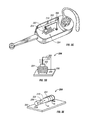
- FIGS. 6A and 6B illustrate a detector 204 including a light source 602 , a photosensor 606 , and a movable reflective surface 604 , 608 therebetween in accordance with an embodiment.
- FIG. 6A illustrates surface 604 that may be suspended, pinned, or loosely trapped, such that surface 604 at a rest state allows photosensor 606 to receive light from light source 602 . Movement of the headset causes surface 604 to move such that photosensor 606 detects a change in the amount of light received and induces fluctuating current flow in a nearby electrical conductor.
- surface 608 may be suspended, pinned, or loosely trapped, such that surface 608 at a rest state impedes light from reaching photosensor 606 .
- Movement of the headset causes surface 608 to move such that photosensor 608 detects a change in the amount of light received and induces fluctuating current flow in a nearby electrical conductor.
- the current flow or output charge produced is amplified, sent to a donned and doffed determination circuit, and processed as described above to determine a state of the headset.
- surface 604 , 608 could include a hole through which light from light source 602 travels, thereby providing changed amount of light received by photosensor 606 as the surface 604 , 608 moves as the headset is moved.
- detector 204 may include a non-motion detector that provides output charges based upon a headset characteristic such as temperature and/or capacitance.
- a headset characteristic such as temperature and/or capacitance.
- FIG. 7 illustrates an infra-red (IR) detector 702 that is sensitive to the temperature of a human body.
- IR infra-red
- the IR detector 702 detects radiation in the wavelengths between 9 and 10 micrometers and provides an electrical signal or output charge that is amplified, sent to a donned and doffed determination circuit, and processed as described above to determine a state of the headset.
- FIGS. 8A and 8B illustrate a pyroelectric sensor 802 that is positioned in close proximity to a point where the headset is intended to contact a user's skin.
- the sensor detects a user is present by determining a skin temperature near 93 degrees Fahrenheit and then providing an electrical signal or output charge that is amplified, sent to a donned and doffed determination circuit, and processed as described above to determine a state of the headset.
- two pyroelectric sensors 802 a and 802 b may be used, with one sensor positioned close to a contact point and the other positioned in a location away from a contact point. Differences (a delta) between the readings of the two sensors can be used to determine a donned or doffed state of the headset, for example if the delta of the two temperature readings is at or above a predetermined level.
- FIG. 9 illustrates an electronic circuit 902 sensitive to capacitance positioned in close proximity to a point where the headset is intended to contact a user's skin.
- the circuit detects an increase in capacitance when the headset is worn and provides an output charge that is amplified, sent to a donned and doffed determination circuit, and processed as described above to determine a state of the headset.
- a micro-switch 1002 can be housed and operably coupled to a PCBA 1006 within the headset device such that an actuator 1004 of the switch is positioned at a touch point 102 a of the headset, thereby being depressed when the headset is worn.
- a determination circuit in PCBA 1006 can monitor the state of the switch, thereby determining the state of the headset.
- a proximity switch 1102 can be housed and operably coupled to a PCBA 1106 within the headset device such that the switch 1102 is positioned at a touch point 102 a of the headset, thereby being triggered or activated when the headset is worn. This use of a proximity switch does not require force from the user's skin, but proximity to the user (without consistent force) such that a change in magnetic field is detected is sufficient to trigger the sensor.
- a determination circuit in PCBA 1106 can monitor the state of the switch, discriminating between a donned or doffed state of the headset.
- Yet another detector that may be used includes a skin resistivity sensor 1202 , as shown in FIG. 12 .
- Conductive materials 1202 can be used at two or more touch points 102 a on the headset, and a circuit in PCBA 1206 can monitor the resistance between these conductive materials, thereby detecting a resistance that is consistent with a predetermined range, thus discriminating between a donned and a doffed state of the headset. That is, when the two or more contact points are in contact with the user's skin, the resistance reading between these contact points will be different from when the headset is not worn, for example the resistance being reduced when the headset is worn due to the skin adding conductance.
- another detector that may be utilized includes a carbon dioxide (CO 2 ) sensor 1302 operably coupled to a PCBA 1306 and a channel 1304 in accordance with an embodiment.
- Sensor 1302 is able to detect an increase of CO 2 , thereby inferring a donned state of a headset.
- sensor 1302 is able to subtract background CO 2 levels to more accurately discriminate between donned and doffed states, and in another embodiment, sensor 1302 and a determination circuit are able to detect patterns of CO 2 levels correlating to human breathing patterns.
- detectors that provide an output charge pattern corresponding to a donned or doffed state of a headset are within the scope of the present invention.
- two or more of the embodiments described above may be used in one headset in order to determine a donned or doffed headset state with greater accuracy and reliability.
- a headset state can be indicated when both detectors indicate the same state.
- a flowchart of a method for determining the donned or doffed state of a headset is illustrated in accordance with an embodiment.
- a headset characteristic such as kinetic energy, temperature, and/or capacitance
- the detector provides an output charge corresponding to a detected characteristic.
- the output charge is amplified and transferred to determination circuit 205 .
- a plurality of output charges are processed by determination circuit 205 to determine an output charge pattern.
- determination circuit 205 correlates the output charge pattern to a donned or doffed state of a headset, in one example comparing the output charge pattern to predetermined output charge profiles that reflect a donned or doffed state of a headset.
- the predetermined output charge profiles may be in look-up tables or a database and may include a variety of parameters, such as for particular headsets and detectors being used.
- the headset state may be sent to server 104 for routing of calls or messages, or for notifying a system regarding volume control for hearing impaired use.
- FIG. 15 illustrates a headset having an LCD, the headset capable of indicating a donned or doffed state and responsively controlling the LCD based on the donned or doffed state.
- Headset 1500 includes a LCD 1502 on the exterior of the headset on which various data is displayed.
- FIG. 16 illustrates a simplified block diagram of the components of the headset shown in FIG. 15 .
- the headset 1500 includes a processor 1602 operably coupled via a bus 1614 to a detector 1604 , a donned and doffed determination circuit 1605 , a memory 1606 , a transducer 1608 , an optional network interface 1610 , and a user interface 1612 .
- User interface 1612 includes an LCD 1616 for displaying alphanumeric data.
- Processor 1602 includes a display controller 1603 for operating LCD 1616 .
- User interface 1612 also allows for manual communication between the headset user and the headset, and in one example includes a variety of input buttons or keys. Such input buttons may include for example on/off buttons or arrow keys. Such input buttons may control, for example, volume, on/off, mute, or menu selection and control access to personal information residing on the headset, such as contacts, passwords, medical information.
- Memory 1606 includes a user interface control application 1620 , including LCD control 1622 .
- Memory 1606 may include a variety of memories, and in one example includes SDRAM, ROM, flash memory, or a combination thereof. Memory 1606 may further include separate memory structures or a single integrated memory structure. In one example, memory 1606 may be used to store passwords, network and telecommunications programs, and/or an operating system (OS). In one embodiment, memory 1606 may store determination circuit 1605 , output charges and patterns thereof from detector 1604 , and predetermined output charge profiles for comparison to determine the donned and doffed state of a headset.
- OS operating system
- Processor 1602 using executable code and applications stored in memory or read into random access memory, performs the necessary functions associated with headset operation described herein.
- the processor 1602 controls the liquid crystal display 1616 via a liquid crystal display driver to display information according to an instruction input in a font of an appropriate size.
- Processor 1602 allows for processing data, in particular managing data between detector 1604 , determination circuit 1605 , and memory 1606 for determining the donned or doffed state of headset 1500 , and determining whether the state of the headset has switched from being doffed to donned.
- Processor 1602 further controls the operating state of LCD 1616 using LCD control 1622 .
- LCD control 1622 may be implemented as either firmware or software.
- processor 1602 is a high performance, highly integrated, and highly flexible system-on-chip (SOC), including signal processing functionality such as echo cancellation/reduction and gain control in another example.
- SOC system-on-chip
- Processor 1602 may include a variety of processors (e.g., digital signal processors), with conventional CPUs being applicable.
- detector 1604 may be a motion detector.
- the motion detector may take a variety of forms such as, for example, a magnet and a coil moving relative to one another, or an acceleration sensor having a mass affixed to a piezoelectric crystal.
- the motion detector may also be a light source, a photosensor, and a movable surface therebetween.
- the detector may include one or more of the following: an infra-red detector, a pyroelectric sensor, a capacitance circuit, a micro-switch, an inductive proximity switch, a skin resistance sensor, or at least two pyroelectric sensors for determining a difference in temperature readings from the two pyroelectric sensors.
- the headset continuously monitors donned and doffed status of the headset. Upon detection that the headset is in a donned status, operation of LCD 1616 is turned off. Upon detection that the headset is in a doffed status, operation of LCD 1616 is turned on.
- the structure and operation of transducer 1608 and network interface 1610 in one example are substantially similar to that described herein above in reference to FIG. 2 .
- FIG. 17 is a flowchart illustrating an exemplary process by which the system in FIG. 16 operates to control the headset LCD.
- a headset characteristic such as kinetic energy, temperature, and/or capacitance
- the detector provides an output charge corresponding to a detected characteristic.
- the output charge is amplified and transferred to determination circuit 205 .
- a plurality of output charges are processed by determination circuit 1605 to determine an output charge pattern.
- determination circuit 1605 correlates the output charge pattern to a donned or doffed state of a headset, in one example comparing the output charge pattern to predetermined output charge profiles that reflect a donned or doffed state of a headset.
- the predetermined output charge profiles may be in look-up tables or a database and may include a variety of parameters, such as for particular headsets and detectors being used.
- the headset controller determines whether the headset is in a donned state. If no at decision block 1710 , then operation of the LCD is enabled at block 1714 . If yes at decision block 1710 , then at block 1712 the operation of the LCD is disabled. For example, the LCD is powered off. In this manner, headset power is conserved by eliminating operation of the LCD when it will not be viewed.
- FIG. 18 illustrates a headset 1800 having user interface inputs 1802 , the headset capable of indicating a donned or doffed state and responsively controlling the user interface inputs 1802 to enter either a locked state, partially locked state, or an active state based on the donned or doffed state.
- User interface inputs 1802 may include, for example, keys, buttons, or a touchpad to control functions such as power, volume, mute, and select buttons.
- Headset 1800 prevents accidental operation of the headset resulting from unintended touching or depression of user interface inputs 1802 , such as when headset 1800 is placed in a bag or pocket. In one example, only certain user interface inputs 1802 are locked while others remain active.
- Headset 1800 may include an optional user interface output such as an LCD on the exterior of the headset on which various data is displayed, which operates as described above in reference to FIGS. 15-17 .
- headset 1800 need not have the LCD. Where headset 1800 includes a donned or doffed controlled LCD, only a subset of user interface inputs 1802 are locked while others remain active, such as those associated with the LCD.
- the function of a particular user interface input key or button varies based upon whether the headset is donned or doffed.
- FIG. 19 illustrates a simplified block diagram of the components of the headset shown in FIG. 18 .
- headset 1800 includes an optional LCD.
- the headset 1800 includes a processor 1902 operably coupled via a bus 1914 to a detector 1904 , a donned and doffed determination circuit 1905 , a memory 1906 , a transducer 1908 , an optional network interface 1910 , and a user interface 1912 .
- User interface 1912 includes an LCD 1916 and associated LCD controller for displaying alphanumeric data.
- User interface 1912 also allows for manual communication between the headset user and the headset, and in one example includes a variety of buttons or user input keys 1917 .
- Memory 1906 includes a user interface control application 1920 , including LCD control 1922 and key lock 1923 .
- Memory 1906 may include a variety of memories, and in one example includes SDRAM, ROM, flash memory, or a combination thereof. Memory 1906 may further include separate memory structures or a single integrated memory structure. In one example, memory 1906 may be used to store passwords, network and telecommunications programs, and/or an operating system (OS). In one embodiment, memory 1906 may store determination circuit 1905 , output charges and patterns thereof from detector 1904 , and predetermined output charge profiles for comparison to determine the donned and doffed state of a headset.
- OS operating system
- Processor 1902 using executable code and applications stored in memory or read into random access memory, performs the necessary functions associated with headset operation described herein.
- the processor 1902 controls the liquid crystal display 1916 via a liquid crystal display driver to display information according to an instruction input in a font of an appropriate size.
- Processor 1902 allows for processing data, in particular managing data between detector 1904 , determination circuit 1905 , and memory 1906 for determining the donned or doffed state of headset 1800 , and determining whether the state of the headset has switched from being doffed to donned.
- Processor 1902 further controls the operating state of user interface input keys 1917 , i.e. whether they are in a locked state or whether they are operational to receive and process user actions.
- the key lock 1923 may be implemented as either firmware or software residing in memory 1906 .
- processor 1902 is a high performance, highly integrated, and highly flexible system-on-chip (SOC), including signal processing functionality such as echo cancellation/reduction and gain control in another example.
- SOC system-on-chip
- Processor 1902 may include a variety of processors (e.g., digital signal processors), with conventional CPUs being applicable.
- detector 1904 may be a motion detector.
- the motion detector may take a variety of forms such as, for example, a magnet and a coil moving relative to one another, or an acceleration sensor having a mass affixed to a piezoelectric crystal.
- the motion detector may also be a light source, a photosensor, and a movable surface therebetween.
- the detector may include one or more of the following: an infra-red detector, a pyroelectric sensor, a capacitance circuit, a micro-switch, an inductive proximity switch, a skin resistance sensor, or at least two pyroelectric sensors for determining a difference in temperature readings from the two pyroelectric sensors.
- the headset continuously monitors donned and doffed status of the headset.
- one or more of the user input keys 1917 are placed in a locked state to avoid inadvertent actions.
- one or more of the user input keys corresponding to initiation of calls, redial, call answer, call reject, stereo play, and volume control may be locked.
- the call answer user input key is not locked when the headset is in a doffed status in order to allow the headset user to easily answer an incoming call.
- the input function is not carried about by the processor.
- the processor may ignore any commands received from the user input key while in a locked state.
- power to the user input key circuitry is disabled.
- headset display LCD 1916 under control of the processor 1902 may show a “Key Lock” or similar message.
- user input keys 1917 Upon detection that the headset is in a donned status, operation of user input keys 1917 is activated.
- the key lock may also be removed or initiated manually, with key lock 1923 providing for a mechanism by which the user may unlock or the headset by depressing a pre-defined sequence of keys.
- User interface output devices may also be placed in a locked or unlocked state responsive to the donned or doffed status.
- FIG. 20 is a flowchart illustrating an exemplary process by which the system in FIG. 19 operates to control the user interface 1912 .
- a headset characteristic such as kinetic energy, temperature, and/or capacitance
- the detector provides an output charge corresponding to a detected characteristic.
- the output charge is amplified and transferred to determination circuit 205 .
- a plurality of output charges are processed by determination circuit 1905 to determine an output charge pattern.
- determination circuit 1905 correlates the output charge pattern to a donned or doffed state of a headset, in one example comparing the output charge pattern to predetermined output charge profiles that reflect a donned or doffed state of a headset.
- the predetermined output charge profiles may be in look-up tables or a database and may include a variety of parameters, such as for particular headsets and detectors being used.
- the headset controller determines whether the headset is in a donned state. If no at decision block 2010 , then at decision block 2014 it is determined if the headset power is on. If yes at decision block 2014 , then at block 2018 one or more inputs of the headset user interface are locked. For example, a “lock enable” flag may be set in the memory of the processor for one or more user input buttons. If the lock enable flag is set, the processor will suspend the normal operation associated with the locked input key. In this manner, inadvertent operation of the headset while being carried or stowed is eliminated. If no at decision block 2014 , the process ends. If yes at decision block 2010 , the operation of the LCD is disabled at block 2012 .
Landscapes
- Engineering & Computer Science (AREA)
- Signal Processing (AREA)
- Computer Networks & Wireless Communication (AREA)
- Physics & Mathematics (AREA)
- Acoustics & Sound (AREA)
- Health & Medical Sciences (AREA)
- Otolaryngology (AREA)
- User Interface Of Digital Computer (AREA)
Abstract
Description
Claims (14)
Priority Applications (1)
| Application Number | Priority Date | Filing Date | Title |
|---|---|---|---|
| US11/895,054 US9590680B1 (en) | 2007-08-22 | 2007-08-22 | Don doff controlled headset user interface |
Applications Claiming Priority (1)
| Application Number | Priority Date | Filing Date | Title |
|---|---|---|---|
| US11/895,054 US9590680B1 (en) | 2007-08-22 | 2007-08-22 | Don doff controlled headset user interface |
Publications (1)
| Publication Number | Publication Date |
|---|---|
| US9590680B1 true US9590680B1 (en) | 2017-03-07 |
Family
ID=58162321
Family Applications (1)
| Application Number | Title | Priority Date | Filing Date |
|---|---|---|---|
| US11/895,054 Expired - Fee Related US9590680B1 (en) | 2007-08-22 | 2007-08-22 | Don doff controlled headset user interface |
Country Status (1)
| Country | Link |
|---|---|
| US (1) | US9590680B1 (en) |
Cited By (11)
| Publication number | Priority date | Publication date | Assignee | Title |
|---|---|---|---|---|
| US10257602B2 (en) | 2017-08-07 | 2019-04-09 | Bose Corporation | Earbud insertion sensing method with infrared technology |
| US10334347B2 (en) | 2017-08-08 | 2019-06-25 | Bose Corporation | Earbud insertion sensing method with capacitive technology |
| US11089429B1 (en) * | 2020-09-18 | 2021-08-10 | Plantronics, Inc. | Indication for correct audio device orientation |
| US11228853B2 (en) | 2020-04-22 | 2022-01-18 | Bose Corporation | Correct donning of a behind-the-ear hearing assistance device using an accelerometer |
| US20220225006A1 (en) * | 2021-01-14 | 2022-07-14 | Apple Inc. | Electronic Devices With Skin Sensors |
| CN114827811A (en) * | 2022-04-25 | 2022-07-29 | 歌尔股份有限公司 | Earphone volume adjusting method, electronic equipment and readable storage medium |
| US20220360880A1 (en) * | 2019-12-25 | 2022-11-10 | Goertek Inc. | Tws earphone, method and apparatus for reducing earphone energy consumption, and medium |
| WO2023178667A1 (en) * | 2022-03-25 | 2023-09-28 | 深圳市大疆创新科技有限公司 | Head-mounted display device and control method |
| KR20230159644A (en) * | 2018-09-21 | 2023-11-21 | 애플 인크. | Force-activated earphone |
| US11910149B2 (en) | 2018-09-21 | 2024-02-20 | Apple Inc. | Force-activated earphone |
| US12203846B2 (en) | 2020-06-08 | 2025-01-21 | Artilux, Inc. | Wideband sensing apparatus and method thereof |
Citations (25)
| Publication number | Priority date | Publication date | Assignee | Title |
|---|---|---|---|---|
| US3109893A (en) | 1961-01-03 | 1963-11-05 | Automatic Elect Lab | Proximity operated loudspeaking telephone |
| US4330690A (en) | 1980-05-01 | 1982-05-18 | Northern Telecom Limited | Telephone group listening systems |
| EP0564164A1 (en) | 1992-04-01 | 1993-10-06 | AT&T Corp. | Capacitive proximity sensors |
| US5576500A (en) * | 1991-02-05 | 1996-11-19 | Direct Measurement Corporation | Coriolis mass flow rate meter having means for modifying angular velocity gradient positioned within a conduit |
| WO2000076177A1 (en) | 1999-06-07 | 2000-12-14 | Telefonaktiebolaget Lm Ericsson (Publ) | Apparatus and method of controlling a voice controlled operation |
| GB2357400A (en) | 1999-12-17 | 2001-06-20 | Nokia Mobile Phones Ltd | Controlling a terminal of a communication system |
| US6272361B1 (en) * | 1997-07-16 | 2001-08-07 | Nokia Mobile Phones Limited | Radio telephone |
| WO2001063888A1 (en) | 2000-02-21 | 2001-08-30 | Ericsson Inc. | Wireless headset with automatic power control |
| US20020021278A1 (en) | 2000-07-17 | 2002-02-21 | Hinckley Kenneth P. | Method and apparatus using multiple sensors in a device with a display |
| US20020068537A1 (en) | 2000-12-04 | 2002-06-06 | Mobigence, Inc. | Automatic speaker volume and microphone gain control in a portable handheld radiotelephone with proximity sensors |
| JP2002278785A (en) | 2001-03-16 | 2002-09-27 | Hitachi Kokusai Electric Inc | Method for distributing program |
| US6518957B1 (en) * | 1999-08-13 | 2003-02-11 | Nokia Mobile Phones Limited | Communications device with touch sensitive screen |
| US6529713B1 (en) * | 1996-09-12 | 2003-03-04 | Nokia Mobile Phones Limited | Handset |
| WO2003103175A1 (en) | 2002-05-30 | 2003-12-11 | Motorola Inc. | Mobile communication device including an extended array sensor |
| US6704428B1 (en) | 1999-03-05 | 2004-03-09 | Michael Wurtz | Automatic turn-on and turn-off control for battery-powered headsets |
| US20040105538A1 (en) | 2000-07-03 | 2004-06-03 | Klaus Goebel | Telephone with a capacitive environment sensor |
| US20050221791A1 (en) | 2004-04-05 | 2005-10-06 | Sony Ericsson Mobile Communications Ab | Sensor screen saver |
| US6965669B2 (en) | 2002-10-29 | 2005-11-15 | International Business Machines Corporation | Method for processing calls in a call center with automatic answering |
| US20060023865A1 (en) | 2004-07-29 | 2006-02-02 | Pamela Nice | Agent detector, with optional agent recognition and log-in capabilities, and optional portable call history storage |
| US20070042816A1 (en) * | 2005-08-15 | 2007-02-22 | Idt Communication Technology Limited | Handheld communication device with key-lock |
| US20070076897A1 (en) | 2005-09-30 | 2007-04-05 | Harald Philipp | Headsets and Headset Power Management |
| US20070121959A1 (en) | 2005-09-30 | 2007-05-31 | Harald Philipp | Headset power management |
| US20070281750A1 (en) * | 2006-06-06 | 2007-12-06 | Ross Cox | Mobile device with themed multimedia effects |
| US20080080705A1 (en) * | 2006-10-02 | 2008-04-03 | Gerhardt John F | Donned and doffed headset state detection |
| US20080242378A1 (en) * | 2007-03-29 | 2008-10-02 | Research In Motion Limited | Headset with multi-button control for a mobile communication device |
-
2007
- 2007-08-22 US US11/895,054 patent/US9590680B1/en not_active Expired - Fee Related
Patent Citations (29)
| Publication number | Priority date | Publication date | Assignee | Title |
|---|---|---|---|---|
| US3109893A (en) | 1961-01-03 | 1963-11-05 | Automatic Elect Lab | Proximity operated loudspeaking telephone |
| US4330690A (en) | 1980-05-01 | 1982-05-18 | Northern Telecom Limited | Telephone group listening systems |
| US5576500A (en) * | 1991-02-05 | 1996-11-19 | Direct Measurement Corporation | Coriolis mass flow rate meter having means for modifying angular velocity gradient positioned within a conduit |
| EP0564164A1 (en) | 1992-04-01 | 1993-10-06 | AT&T Corp. | Capacitive proximity sensors |
| US6529713B1 (en) * | 1996-09-12 | 2003-03-04 | Nokia Mobile Phones Limited | Handset |
| US6272361B1 (en) * | 1997-07-16 | 2001-08-07 | Nokia Mobile Phones Limited | Radio telephone |
| US20040258253A1 (en) * | 1999-03-05 | 2004-12-23 | Michael Wurtz | Automatic turn-on and turn-off control for battery-powered headsets |
| US6704428B1 (en) | 1999-03-05 | 2004-03-09 | Michael Wurtz | Automatic turn-on and turn-off control for battery-powered headsets |
| WO2000076177A1 (en) | 1999-06-07 | 2000-12-14 | Telefonaktiebolaget Lm Ericsson (Publ) | Apparatus and method of controlling a voice controlled operation |
| US6518957B1 (en) * | 1999-08-13 | 2003-02-11 | Nokia Mobile Phones Limited | Communications device with touch sensitive screen |
| US20010044318A1 (en) * | 1999-12-17 | 2001-11-22 | Nokia Mobile Phones Ltd. | Controlling a terminal of a communication system |
| GB2357400A (en) | 1999-12-17 | 2001-06-20 | Nokia Mobile Phones Ltd | Controlling a terminal of a communication system |
| US7010332B1 (en) * | 2000-02-21 | 2006-03-07 | Telefonaktiebolaget Lm Ericsson(Publ) | Wireless headset with automatic power control |
| WO2001063888A1 (en) | 2000-02-21 | 2001-08-30 | Ericsson Inc. | Wireless headset with automatic power control |
| US20040105538A1 (en) | 2000-07-03 | 2004-06-03 | Klaus Goebel | Telephone with a capacitive environment sensor |
| US20020021278A1 (en) | 2000-07-17 | 2002-02-21 | Hinckley Kenneth P. | Method and apparatus using multiple sensors in a device with a display |
| US20020068537A1 (en) | 2000-12-04 | 2002-06-06 | Mobigence, Inc. | Automatic speaker volume and microphone gain control in a portable handheld radiotelephone with proximity sensors |
| JP2002278785A (en) | 2001-03-16 | 2002-09-27 | Hitachi Kokusai Electric Inc | Method for distributing program |
| WO2003103175A1 (en) | 2002-05-30 | 2003-12-11 | Motorola Inc. | Mobile communication device including an extended array sensor |
| US6965669B2 (en) | 2002-10-29 | 2005-11-15 | International Business Machines Corporation | Method for processing calls in a call center with automatic answering |
| WO2005099105A1 (en) | 2004-04-05 | 2005-10-20 | Sony Ericsson Mobile Communications Ab | Sensor screen saver |
| US20050221791A1 (en) | 2004-04-05 | 2005-10-06 | Sony Ericsson Mobile Communications Ab | Sensor screen saver |
| US20060023865A1 (en) | 2004-07-29 | 2006-02-02 | Pamela Nice | Agent detector, with optional agent recognition and log-in capabilities, and optional portable call history storage |
| US20070042816A1 (en) * | 2005-08-15 | 2007-02-22 | Idt Communication Technology Limited | Handheld communication device with key-lock |
| US20070076897A1 (en) | 2005-09-30 | 2007-04-05 | Harald Philipp | Headsets and Headset Power Management |
| US20070121959A1 (en) | 2005-09-30 | 2007-05-31 | Harald Philipp | Headset power management |
| US20070281750A1 (en) * | 2006-06-06 | 2007-12-06 | Ross Cox | Mobile device with themed multimedia effects |
| US20080080705A1 (en) * | 2006-10-02 | 2008-04-03 | Gerhardt John F | Donned and doffed headset state detection |
| US20080242378A1 (en) * | 2007-03-29 | 2008-10-02 | Research In Motion Limited | Headset with multi-button control for a mobile communication device |
Non-Patent Citations (1)
| Title |
|---|
| Gregory, Peter; Doria, Tom; Stegh, Chris; Su, Jim; SIP Communications for Dummies, Avaya Custom Edition, 2006, Wiley Publishing, Inc., Hoboken, NJ, USA. |
Cited By (17)
| Publication number | Priority date | Publication date | Assignee | Title |
|---|---|---|---|---|
| US10257602B2 (en) | 2017-08-07 | 2019-04-09 | Bose Corporation | Earbud insertion sensing method with infrared technology |
| US10334347B2 (en) | 2017-08-08 | 2019-06-25 | Bose Corporation | Earbud insertion sensing method with capacitive technology |
| KR20230159644A (en) * | 2018-09-21 | 2023-11-21 | 애플 인크. | Force-activated earphone |
| US12133042B2 (en) | 2018-09-21 | 2024-10-29 | Apple Inc. | Force-activated stylus |
| US12101590B2 (en) | 2018-09-21 | 2024-09-24 | Apple Inc. | Force-activated earphone |
| US11917355B2 (en) | 2018-09-21 | 2024-02-27 | Apple Inc. | Force-activated earphone |
| US11917354B2 (en) * | 2018-09-21 | 2024-02-27 | Apple Inc. | Force-activated earphone |
| US11910149B2 (en) | 2018-09-21 | 2024-02-20 | Apple Inc. | Force-activated earphone |
| US11937039B2 (en) * | 2019-12-25 | 2024-03-19 | Goertek Inc. | TWS earphone, method and apparatus for reducing earphone energy consumption, and medium |
| US20220360880A1 (en) * | 2019-12-25 | 2022-11-10 | Goertek Inc. | Tws earphone, method and apparatus for reducing earphone energy consumption, and medium |
| US11228853B2 (en) | 2020-04-22 | 2022-01-18 | Bose Corporation | Correct donning of a behind-the-ear hearing assistance device using an accelerometer |
| US12203846B2 (en) | 2020-06-08 | 2025-01-21 | Artilux, Inc. | Wideband sensing apparatus and method thereof |
| US11089429B1 (en) * | 2020-09-18 | 2021-08-10 | Plantronics, Inc. | Indication for correct audio device orientation |
| US20220225006A1 (en) * | 2021-01-14 | 2022-07-14 | Apple Inc. | Electronic Devices With Skin Sensors |
| US12317024B2 (en) * | 2021-01-14 | 2025-05-27 | Apple Inc. | Electronic devices with skin sensors |
| WO2023178667A1 (en) * | 2022-03-25 | 2023-09-28 | 深圳市大疆创新科技有限公司 | Head-mounted display device and control method |
| CN114827811A (en) * | 2022-04-25 | 2022-07-29 | 歌尔股份有限公司 | Earphone volume adjusting method, electronic equipment and readable storage medium |
Similar Documents
| Publication | Publication Date | Title |
|---|---|---|
| US9590680B1 (en) | Don doff controlled headset user interface | |
| US8009874B2 (en) | User validation of body worn device | |
| US8538009B2 (en) | Donned and doffed headset state detection | |
| US8315876B2 (en) | Headset wearer identity authentication with voice print or speech recognition | |
| CN104160355B (en) | Systems and methods for reducing the occurrence of undesired operations in electronic devices | |
| US20160036996A1 (en) | Electronic device with static electric field sensor and related method | |
| CN105577924B (en) | Method, wearable device and the terminal device of wearable device controlling terminal equipment | |
| US20120086551A1 (en) | Headset Ear Detection | |
| US20150301615A1 (en) | Impact and contactless gesture inputs for docking stations | |
| JP2016192217A (en) | Terminal control method, and device, and terminal | |
| CN104868932A (en) | Wearable electronic equipment, communication method and device thereof | |
| CN107566604B (en) | Message reminding control method and user terminal | |
| US11099635B2 (en) | Blow event detection and mode switching with an electronic device | |
| CN114153334B (en) | Electronic device and control method and control device thereof | |
| WO2016027632A1 (en) | Watching system, watching detection device, and watching notification device | |
| JP2005287688A (en) | Information communication terminal and biological information measurement system | |
| JP6786245B2 (en) | Information processing device | |
| US12524060B2 (en) | Activity monitoring for electronic device | |
| WO2015187302A1 (en) | Mobile device including a centrally located earpiece | |
| CN109151214A (en) | A kind of state based reminding method and mobile terminal | |
| JP4821837B2 (en) | Wireless communication apparatus, wireless communication method, and wireless communication program | |
| CN208143315U (en) | A kind of reminding incoming call of mobile phone and answering device | |
| CN110750420B (en) | Method and device for preventing equipment from sliding, electronic equipment and medium | |
| WO2015041206A1 (en) | Automatic appliance-activating device, handheld information appliance, handheld-information-appliance system, and program | |
| CN113017583A (en) | Blood pressure measuring method and device |
Legal Events
| Date | Code | Title | Description |
|---|---|---|---|
| AS | Assignment |
Owner name: PLANTRONICS, INC., CALIFORNIA Free format text: ASSIGNMENT OF ASSIGNORS INTEREST;ASSIGNORS:REUSS, EDWARD L.;ELABIDI, DIANE;SIGNING DATES FROM 20070821 TO 20070822;REEL/FRAME:019793/0422 |
|
| STCF | Information on status: patent grant |
Free format text: PATENTED CASE |
|
| AS | Assignment |
Owner name: WELLS FARGO BANK, NATIONAL ASSOCIATION, NORTH CAROLINA Free format text: SECURITY AGREEMENT;ASSIGNORS:PLANTRONICS, INC.;POLYCOM, INC.;REEL/FRAME:046491/0915 Effective date: 20180702 Owner name: WELLS FARGO BANK, NATIONAL ASSOCIATION, NORTH CARO Free format text: SECURITY AGREEMENT;ASSIGNORS:PLANTRONICS, INC.;POLYCOM, INC.;REEL/FRAME:046491/0915 Effective date: 20180702 |
|
| MAFP | Maintenance fee payment |
Free format text: PAYMENT OF MAINTENANCE FEE, 4TH YEAR, LARGE ENTITY (ORIGINAL EVENT CODE: M1551); ENTITY STATUS OF PATENT OWNER: LARGE ENTITY Year of fee payment: 4 |
|
| AS | Assignment |
Owner name: POLYCOM, INC., CALIFORNIA Free format text: RELEASE OF PATENT SECURITY INTERESTS;ASSIGNOR:WELLS FARGO BANK, NATIONAL ASSOCIATION;REEL/FRAME:061356/0366 Effective date: 20220829 Owner name: PLANTRONICS, INC., CALIFORNIA Free format text: RELEASE OF PATENT SECURITY INTERESTS;ASSIGNOR:WELLS FARGO BANK, NATIONAL ASSOCIATION;REEL/FRAME:061356/0366 Effective date: 20220829 |
|
| AS | Assignment |
Owner name: HEWLETT-PACKARD DEVELOPMENT COMPANY, L.P., TEXAS Free format text: NUNC PRO TUNC ASSIGNMENT;ASSIGNOR:PLANTRONICS, INC.;REEL/FRAME:065549/0065 Effective date: 20231009 |
|
| FEPP | Fee payment procedure |
Free format text: MAINTENANCE FEE REMINDER MAILED (ORIGINAL EVENT CODE: REM.); ENTITY STATUS OF PATENT OWNER: LARGE ENTITY |
|
| LAPS | Lapse for failure to pay maintenance fees |
Free format text: PATENT EXPIRED FOR FAILURE TO PAY MAINTENANCE FEES (ORIGINAL EVENT CODE: EXP.); ENTITY STATUS OF PATENT OWNER: LARGE ENTITY |
|
| STCH | Information on status: patent discontinuation |
Free format text: PATENT EXPIRED DUE TO NONPAYMENT OF MAINTENANCE FEES UNDER 37 CFR 1.362 |
|
| FP | Lapsed due to failure to pay maintenance fee |
Effective date: 20250307 |