US9588024B1 - Stacked modular conditioning system and method - Google Patents
Stacked modular conditioning system and method Download PDFInfo
- Publication number
- US9588024B1 US9588024B1 US14/198,393 US201414198393A US9588024B1 US 9588024 B1 US9588024 B1 US 9588024B1 US 201414198393 A US201414198393 A US 201414198393A US 9588024 B1 US9588024 B1 US 9588024B1
- Authority
- US
- United States
- Prior art keywords
- fluid
- components
- modular
- component
- sample
- Prior art date
- Legal status (The legal status is an assumption and is not a legal conclusion. Google has not performed a legal analysis and makes no representation as to the accuracy of the status listed.)
- Active, expires
Links
- 230000003750 conditioning effect Effects 0.000 title claims abstract description 68
- 238000000034 method Methods 0.000 title claims abstract description 37
- 239000000523 sample Substances 0.000 claims abstract description 88
- 238000012544 monitoring process Methods 0.000 claims abstract description 42
- 238000005070 sampling Methods 0.000 claims abstract description 26
- 239000007788 liquid Substances 0.000 claims abstract description 8
- 230000009467 reduction Effects 0.000 claims abstract description 8
- 239000012530 fluid Substances 0.000 claims description 113
- 239000012528 membrane Substances 0.000 claims description 12
- 238000005191 phase separation Methods 0.000 claims description 10
- 230000001143 conditioned effect Effects 0.000 claims description 9
- 238000005260 corrosion Methods 0.000 claims description 7
- 230000007797 corrosion Effects 0.000 claims description 7
- 230000003189 isokinetic effect Effects 0.000 claims description 6
- 238000012806 monitoring device Methods 0.000 claims description 6
- 238000004891 communication Methods 0.000 claims description 5
- 230000000694 effects Effects 0.000 claims description 3
- 238000003780 insertion Methods 0.000 claims 7
- 230000037431 insertion Effects 0.000 claims 7
- 230000009834 selective interaction Effects 0.000 claims 3
- 238000013508 migration Methods 0.000 claims 2
- 230000005012 migration Effects 0.000 claims 2
- 230000004888 barrier function Effects 0.000 claims 1
- 230000003993 interaction Effects 0.000 claims 1
- 230000002452 interceptive effect Effects 0.000 claims 1
- 239000007789 gas Substances 0.000 abstract description 18
- 230000008569 process Effects 0.000 abstract description 12
- VNWKTOKETHGBQD-UHFFFAOYSA-N methane Chemical compound C VNWKTOKETHGBQD-UHFFFAOYSA-N 0.000 abstract description 10
- 239000003345 natural gas Substances 0.000 abstract description 5
- 238000001914 filtration Methods 0.000 abstract 1
- 238000001816 cooling Methods 0.000 description 7
- 230000007704 transition Effects 0.000 description 4
- 230000008901 benefit Effects 0.000 description 3
- 239000000463 material Substances 0.000 description 3
- 230000007246 mechanism Effects 0.000 description 3
- 238000007789 sealing Methods 0.000 description 3
- 239000004215 Carbon black (E152) Substances 0.000 description 1
- 239000000538 analytical sample Substances 0.000 description 1
- 239000005388 borosilicate glass Substances 0.000 description 1
- 239000003638 chemical reducing agent Substances 0.000 description 1
- 238000009833 condensation Methods 0.000 description 1
- 230000005494 condensation Effects 0.000 description 1
- 239000000470 constituent Substances 0.000 description 1
- 230000003111 delayed effect Effects 0.000 description 1
- 230000001419 dependent effect Effects 0.000 description 1
- 238000013461 design Methods 0.000 description 1
- 229930195733 hydrocarbon Natural products 0.000 description 1
- 150000002430 hydrocarbons Chemical class 0.000 description 1
- 230000006872 improvement Effects 0.000 description 1
- 238000009434 installation Methods 0.000 description 1
- 239000007791 liquid phase Substances 0.000 description 1
- 239000006194 liquid suspension Substances 0.000 description 1
- 238000012423 maintenance Methods 0.000 description 1
- 239000002184 metal Substances 0.000 description 1
- 239000000203 mixture Substances 0.000 description 1
- 239000004033 plastic Substances 0.000 description 1
- 229920003023 plastic Polymers 0.000 description 1
- 238000002360 preparation method Methods 0.000 description 1
- 230000001681 protective effect Effects 0.000 description 1
- 238000007670 refining Methods 0.000 description 1
- 230000008439 repair process Effects 0.000 description 1
- 239000000126 substance Substances 0.000 description 1
- 238000012360 testing method Methods 0.000 description 1
- 229920001169 thermoplastic Polymers 0.000 description 1
- 239000004416 thermosoftening plastic Substances 0.000 description 1
- 238000012549 training Methods 0.000 description 1
- 239000012808 vapor phase Substances 0.000 description 1
- 230000003245 working effect Effects 0.000 description 1
Images


Classifications
-
- G—PHYSICS
- G01—MEASURING; TESTING
- G01N—INVESTIGATING OR ANALYSING MATERIALS BY DETERMINING THEIR CHEMICAL OR PHYSICAL PROPERTIES
- G01N1/00—Sampling; Preparing specimens for investigation
- G01N1/02—Devices for withdrawing samples
- G01N1/22—Devices for withdrawing samples in the gaseous state
- G01N1/2247—Sampling from a flowing stream of gas
-
- G—PHYSICS
- G01—MEASURING; TESTING
- G01N—INVESTIGATING OR ANALYSING MATERIALS BY DETERMINING THEIR CHEMICAL OR PHYSICAL PROPERTIES
- G01N33/00—Investigating or analysing materials by specific methods not covered by groups G01N1/00 - G01N31/00
- G01N33/0004—Gaseous mixtures, e.g. polluted air
- G01N33/0009—General constructional details of gas analysers, e.g. portable test equipment
- G01N33/0011—Sample conditioning
-
- G—PHYSICS
- G01—MEASURING; TESTING
- G01N—INVESTIGATING OR ANALYSING MATERIALS BY DETERMINING THEIR CHEMICAL OR PHYSICAL PROPERTIES
- G01N1/00—Sampling; Preparing specimens for investigation
- G01N1/02—Devices for withdrawing samples
- G01N1/22—Devices for withdrawing samples in the gaseous state
- G01N1/2202—Devices for withdrawing samples in the gaseous state involving separation of sample components during sampling
- G01N1/2205—Devices for withdrawing samples in the gaseous state involving separation of sample components during sampling with filters
-
- G—PHYSICS
- G01—MEASURING; TESTING
- G01N—INVESTIGATING OR ANALYSING MATERIALS BY DETERMINING THEIR CHEMICAL OR PHYSICAL PROPERTIES
- G01N1/00—Sampling; Preparing specimens for investigation
- G01N1/02—Devices for withdrawing samples
- G01N1/22—Devices for withdrawing samples in the gaseous state
- G01N1/2226—Sampling from a closed space, e.g. food package, head space
- G01N2001/2238—Sampling from a closed space, e.g. food package, head space the gas being compressed or pressurized
Definitions
- a system for sampling and/or conditioning a process gas such as natural gas or the like utilizing two or more modular components, each having unique conditioning or monitoring features or the like, which components are formed to be slidingly received in a receiver so as to be stacked one upon the other for sealed engagement, forming a serial flow-through passage to provide conditioning, monitoring, or other features as the gas flows therethrough.
- Probes may be used to extract physical samples from the process gas, which may contain entrained liquid.
- real-time or time delayed monitoring via sensors or the like (for example, temperature, flow, liquid phase content, pH, etc) provides information on the process gas and its attributes. Corrosion coupons or other exposure indicators are likewise used to provide valuable data.
- stepped or otherwise controlled pressure reduction may be desirable to avoid adiabatic pressure drop, which may occur where to great a pressure drop is made in a single stage of pressure reduction. This should be avoided as too great a pressure drop in a single stage could result in JT cooling of the gas below its hydrocarbon dew point, resulting in sample gas composition distortion and potentially inaccurate data on the process gas stream.
- Multi-stage, prior art pressure regulators can be bulky and typically are limited to two stages, and in the past, little or no consideration was given to minimizing the J-T cooling effect in third party systems.
- Past modular sample conditioning systems employing two or more stages have been typically bulky and located external the fluid source, may be exposed to the elements and ambient temperature (unless insulated and/or heated or cooled to the temperature of the flow stream), and may require specialized on-site setup and calibration.
- Current modular sample conditioning systems are comprised of individual sample conditioning components mounted a plate or base module near the analyzer. Examples of such systems include Parker's Intraflow system, Swagelok, and Circor Tech. These current modular sample conditioning systems are housed near the analyzer, typically in heated analyzer shelters.
- the present invention contemplates a modular sample conditioning system which is compact, robust, easily assembled, diverse in conditioning capabilities, and able to be utilized as a probe tip or otherwise in conjunction with a sample probe or the like, or other use, and thus operate at the prevailing pressure and temperature of the process gas stream.
- the present system is designed to provide a modular sampling system assembly having diverse functionality, and which can be easily customized for each application, and easily reconfigured as the need arises by a user, without the need for extensive training.
- the system of the present invention may be used for sampling and/or conditioning natural gas in preparation for analysis, using multiple stacked internal analytical sample conditioning components that may be utilized inside a probe that is inside a pressurized vessel such as a pipeline or other pressurized vessel or the like.
- a benefit of such an installation is that the components would be at the prevailing temperature and pressure of the interior of the vessel, and would not require additional shelter or enclosure, providing a reduced footprint.
- the preferred embodiment of the present invention comprises a conditioning assembly comprising a receiver formed to slidingly receive conditioning components which are stacked upon one another for serial flow therethrough.
- the components utilized in the present device may comprise, for example, component bodies formed to receive sample conditioning sub-components such as membrane separators (e.g., phase separation membrane) regulators and regulator components, isokinetic sampling components, coalescing filters, particulate filters (screens, sintered metal, sintered plastics, thermoplastics, borosilicate glass, etc.), inertial separators, valves (i.e., throttling, needle, metering, ball, switching, etc) and others.
- a single sub-component could be formed to have a single function, or multiple functions, as desired.
- conditioning component is not intended to be limiting as other components may likewise be used in the present invention, including sensors and monitoring components such as corrosion coupons, wireless monitoring devices such as temperature sensors (for example, thermistor sensors, thermometers, etc) wireless monitoring devices, flow meters, pressure sensors, moisture sensors, gas sensors (e.g. H2S and others) liquid detectors, etc.
- sensors and monitoring components such as corrosion coupons, wireless monitoring devices such as temperature sensors (for example, thermistor sensors, thermometers, etc) wireless monitoring devices, flow meters, pressure sensors, moisture sensors, gas sensors (e.g. H2S and others) liquid detectors, etc.
- the fluid passing therethrough (which may comprise gas or a gas with liquid suspension, or even liquid) interacts with each said component in some capacity, be it to, for example, condition (in the case of a phase separation membrane, pressure regulator, etc) or provide data in a monitoring context (in the case of temperature sensors, flow meters, pressure sensors, etc), so the term “interacted fluid” may be used to describe fluid which has passed through any of the above components.
- the present invention would be particularly suitable for providing a series of pressure regulators in stepped reduction stages to limit or prevent JT cooling, as shown in FIGS. 7-8F in the present application.
- An example of the use of stepped pressure reduction using pressure regulators in series may be found in Mayeaux now U.S. Pat. No. 8,616,228, the content of which are incorporated herein by reference thereto.
- the above component list is intended to be illustrative only, and not limiting, as there are many other conditioning/monitoring components which may likewise be used with the present system.
- the present invention is not on the conditioning/monitoring devices/techniques per se. Rather, the present invention provides a modularized system to readily assemble/customize a conditioning/monitoring solution to meet a users demands, as an easily customizable solution is not believed readily available, and there is a long felt, but unresolved need for such a solution, especially when one considers that the every fluid (in the preferred embodiment in this case, natural gas) flow has different characteristics which may require custom solutions in sampling/monitoring same.
- two or more modular conditioning components are formed such that the diameter of the base of each component body includes a seal which slidingly engages the inner wall of a receiver such that, with the conditioning components stacked upon one another the components are enclosed so as to allow the flow of the sample serially therethrough, forming a conditioning and/or monitoring flow through passage through the assembly.
- the receiver is thereby formed to receive the stacked components, and engage the stacked components so as to retain the stack within the assembly in fixed fashion in use, but allow for easy disengagement and reconfiguration, maintenance, and/or repair when desired.
- the present invention also contemplates a unique sealing mechanism so as to releaseably seal the stacked components to one another within the receiver, as well as a unique method of sampling utilizing an easily customizable modular sample component assembly configured for diverse applications, including use as a sample probe tip.
- the present invention contemplates a unique modular sampling/conditioning/monitoring component, which is designed to receive one or more sub-components therein of diverse functionality, so as to provide easily customizable configurations, while maintaining general uniform characteristics for sealable, serial-flow in a stacked engagement.
- FIG. 1 is a side view of an exemplary stackable modular sample conditioning component of the preferred embodiment of the present invention, with exemplary inner workings shown in phantom, in this case, a side-mounted, flow-through pressure regulator.
- FIG. 2 is a side view of three stackable modular sample conditioning components in stacked configuration.
- FIG. 3A is a side view illustrating the stacked modular sampling components of FIG. 2 , having a first threaded insert with flow passage forming the base of the stack, said first threaded insert formed to engage the ID of a receiver or cartridge, and a transition piece at the top of the stack to engage the inlet of a probe or the like.
- FIG. 3B is a side view illustrating an exemplary receiver or cartridge formed to receive the stack of FIG. 3A .
- FIG. 3C is a side, cut-away view of the stacked modular sampling components of FIG. 3A engaging the receiver of FIG. 3B .
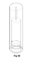
- FIG. 3D is a side, perspective view of an alternative of the receiver or cartridge of FIG. 3B .
- FIG. 4A is a perspective view of the stacked modular sampling components with base and transition piece of FIG. 3A .
- FIG. 4B is a side view of FIG. 4A , illustrating the sub-components and modular sampling components in phantom.
- FIG. 4C is a bottom, end view of the apparatus of FIG. 4B .
- FIG. 4D is a top, end view of the apparatus of FIG. 4B .
- FIG. 5A is a side view illustrating a probe tip adapter to allow the receiver with conditioning component stack (with sub-components situated therein) to be mounted as a sampling probe tip for analytical sampling of a process gas stream or the like.
- FIG. 5B is a side view illustrating an alternative receiver or cartridge configuration of FIG. 5A to receive the stack of FIG. 3A shown mounted to a probe tip.
- FIG. 5C is a partial, cut-away view of the device of FIG. 5B shown without the receiver/cartridge, engaging an exemplary modular sample component stack with sub-components situated therein.
- FIG. 6 is a side view of a probe tip cartridge/protective shroud having multiple sampling components in the form of staged pressure regulators for controlled reduction in fluid pressure (for example, to lessen or prevent JT cooling), the regulators situated in stacked fashion (in phantom) in a receiver, preceded by a phase separation membrane at the (extended) probe tip.
- staged pressure regulators for controlled reduction in fluid pressure (for example, to lessen or prevent JT cooling)
- the regulators situated in stacked fashion (in phantom) in a receiver, preceded by a phase separation membrane at the (extended) probe tip.
- FIG. 7 is a side, cut-away view of the exemplary probe tip of FIG. 6 and the various components in stacked, serial, flow-through communication therethrough.
- FIGS. 8A-8F illustrate the components and working relationship of the various elements of the probe carrying the probe tip of FIG. 7 .
- the preferred embodiment of the present invention utilizes a unique modular component 1 which may have one or more sampling, fluid conditioning or monitoring functions or the like, each component comprising a component body 1 ′ having an outer wall 3 , and first 4 and second 4 ′ ends having inlet 5 and outlet 5 ′ flow passages, respectively.
- the component body also has a base 7 at the first end 4 , the base having a seal 7 ′ thereabout to engage the inner wall of the receiver (inner wall 22 of the receiver 23 is shown in FIGS. 4 and 5 and discussed in more detail infra.)
- the component body 1 ′ has an opening 10 formed in the outer wall 3 of the unit forming a cavity 9 ′ formed to receive a sub-component 9 (and which may include o-ring seals 11 ′, 11 ′′), which sub-component is configured to provide the desired functionality with regard to fluid conditioning, monitoring, etc, and is designed for inter-changeability engaging the passages formed in the modular component 1 .
- the opening 10 formed to receive the sub-component may be threaded or not, depending upon the type of sub-component used and its operation. For example, presently the opening 10 may not be threaded for use with the pressure regulator stage as shown because it must move to operate, although many other sub-components would threadingly engage opening 10 , as currently envisioned.
- the exemplary sub-component 9 shown in FIG. 1 comprises a pressure regulator stage or reducer (for example, a first stage regulator), which is inserted into the opening 10 and engages same (sealed via o-ring, for example), such that said regulator stage or the like is situated largely within the component body, and does not protrude past the largest diameter of the sidewall.
- a pressure regulator stage or reducer for example, a first stage regulator
- the sub-component 9 (as indicated, a regulator stage) is configured to engage the inlet 5 and outlet 5 ′ flow passages in its operation.
- a sealing mechanism in the form of an o-ring is shown at the end of the component, so as to provide a fluid-tight seal between adjacent, stacked components.
- the preferred embodiment of the present invention employs multiple stacked components to provide flow through modular conditioning, monitoring, or the like.
- the stacked components could be secured to one another (via example, threaded or snapped connections, or external brackets or the like), and may be simply stacked in sliding engagement with a receiver (the example illustrated in the present FIGS. 1-6 ) or cartridge, or may be some combination thereof.
- the components are selected depending upon the fluid conditioning or monitoring required, then stacked in the desired order of conditioning/monitoring.
- first 13 , second 13 ′ and third 13 ′′ components are shown stacked upon one another ( FIG. 2 ), the first 13 component having installed as its sub-component 12 an inlet filter, membrane filter, coalescing filter, particulate filter or the like, the second 13 ′ component having at its sub-component 12 ′ a stage one regulator, and the third 13 ′′ component having a sub-component 12 ′′ comprising a second stage regulator.
- each component has at its second end 4 ′ a sealing mechanism ( 11 in FIG. 1 or 51 in FIG. 2 ) such as an o-ring or the like situated about the outlet flow passage 5 ′ to provide sealed fluid passage communication to the first end 4 of the stacked component or other item engaged thereto (which may serve as a reference port for a regulator, and each component has at its first end 4 a base 7 which has a seal 7 ′ about its outer perimeter formed to engage the inner wall 22 of receiver 23 .
- a sealing mechanism 11 in FIG. 1 or 51 in FIG. 2
- each component has at its first end 4 a base 7 which has a seal 7 ′ about its outer perimeter formed to engage the inner wall 22 of receiver 23 .
- the outer wall 3 of the component body is formed to have a slightly lesser width 17 ′ (or diameter in the case of a cylindrical configuration) than the inner wall 22 (or ID in the case of a cylinder) of the receiver 23 for sliding engagement and also so as to form a space 18 therebetween (in the present, preferred embodiment, the space being about 0.005′′), said space 18 enclosed via opposing component base seals 7 ′, 7 ′′ engaging the inner wall of the receiver, forming an enclosed passage allowing outflow 20 from the sub-component outlet 16 to inlet passage 21 leading to the next component, in the present example, a stage two regulator.
- outlet flow passage 26 , 50 provides the reference pressure for the stage two regulator stacked thereupon.
- a threaded insert 27 is applied to the first end of the first component 13 to engage the threaded opening 27 ′ of the receiver 23 or cartridge, to retain the stack of components solidly within the receiver or cartridge, and apply pressure to the stack of components to facilitate the o-ring sale between said components, while the flow passage formed therethrough (in FIG. 4 , inlet 53 , outlet 54 ) allows passage of the flow to or from the components.
- a transition piece 28 may be provided to engage the second end of the last component forming the stack, the transition piece engaging the outlets of said last component and directing same via passages to form the desired outflow for the system, as well as being formed to engage the inlet of the receiver, cartridge, probe or other item having its inlet engaged thereto.
- the cartridge with modular sample components stacked therein may be mounted to the tip of a fluid probe or the like via a probe tip adapter to allow the stack to serially engage a process fluid stream.
- fluid from the fluid stream would into the probe tip, through the first then subsequent conditioning components in serial fashion, and thereby provide a flow of conditioned fluid from the process fluid stream at prevailing fluid pressure and temperature to the probe, providing an analytically correct sample, while lessening any JT cooling effect.
- FIGS. 6-8D Another example of stacked conditioning components, in this example contained in a cartridge configured to form a probe tip extension 70 mounted to a probe, can be found in FIGS. 6-8D .
- a probe tip as situated at its opening 71 a phase separation membrane 72 , coalescing filter, particulate filter, or the like, followed by a receiver 73 formed in the cartridge to contain first 74 , second 74 ′ and third 74 ′′ stage, stacked pressure regulator sub-components side-mounted 75 in three respective conditioning components 76 , 76 ′, 76 ′′ of a uniform outer diameter (OD) 77 slidingly engaging the inner diameter (ID) 78 of receiver 73 . While pressure regulators as conditioning sub-components are illustrated as used, conditioning sub-components of other functions may be selected depending upon the fluid conditioning desired, then stacked in the desired order of conditioning.
- the cartridge with modular sample components therein is shown mounted to a tip 79 of a probe 80 or the like (and may include a 4th stage adjustable regulator 81 with opposing threaded ends for engagement therebetween) to selectively engage a process gas stream in a pressurized vessel such as a pipeline, so that the fluid passes into the probe tip, through the phase separation membrane 72 then the first and subsequent conditioning components, and thereby provide a flow of conditioned fluid from the process gas stream at prevailing pressure and temperature to the probe, in a manner which could lessen or prevent JT cooling.
- a pressurized vessel such as a pipeline
- the present invention contemplates the unique and useful improvement of providing modular conditioning components, each having their own function and specification, but designed to be interchangeably stacked depending upon the conditions and desired outcome which may be used as a connected stack and/or placed into a receiver or cartridge, thereby providing a custom conditioning and/or monitoring solution.
Landscapes
- Life Sciences & Earth Sciences (AREA)
- Chemical & Material Sciences (AREA)
- Health & Medical Sciences (AREA)
- Engineering & Computer Science (AREA)
- Analytical Chemistry (AREA)
- Physics & Mathematics (AREA)
- Biochemistry (AREA)
- General Health & Medical Sciences (AREA)
- General Physics & Mathematics (AREA)
- Immunology (AREA)
- Pathology (AREA)
- Food Science & Technology (AREA)
- Medicinal Chemistry (AREA)
- Combustion & Propulsion (AREA)
- Biomedical Technology (AREA)
- Molecular Biology (AREA)
- Sampling And Sample Adjustment (AREA)
Abstract
Description
Claims (53)
Priority Applications (1)
| Application Number | Priority Date | Filing Date | Title |
|---|---|---|---|
| US14/198,393 US9588024B1 (en) | 2013-03-05 | 2014-03-05 | Stacked modular conditioning system and method |
Applications Claiming Priority (2)
| Application Number | Priority Date | Filing Date | Title |
|---|---|---|---|
| US201361772880P | 2013-03-05 | 2013-03-05 | |
| US14/198,393 US9588024B1 (en) | 2013-03-05 | 2014-03-05 | Stacked modular conditioning system and method |
Publications (1)
| Publication Number | Publication Date |
|---|---|
| US9588024B1 true US9588024B1 (en) | 2017-03-07 |
Family
ID=58163551
Family Applications (1)
| Application Number | Title | Priority Date | Filing Date |
|---|---|---|---|
| US14/198,393 Active 2034-08-08 US9588024B1 (en) | 2013-03-05 | 2014-03-05 | Stacked modular conditioning system and method |
Country Status (1)
| Country | Link |
|---|---|
| US (1) | US9588024B1 (en) |
Cited By (3)
| Publication number | Priority date | Publication date | Assignee | Title |
|---|---|---|---|---|
| EP3521820A1 (en) * | 2018-02-06 | 2019-08-07 | ExTeVent AB | Gas analyser |
| US11144078B2 (en) | 2019-09-23 | 2021-10-12 | Mustang Sampling, Llc | Adjustable multistage pressure reducing regulator |
| US12105537B2 (en) | 2019-09-23 | 2024-10-01 | Mustang Sampling, Llc | Adjustable multistage pressure reducing regulator with augmented thermal control |
Citations (10)
| Publication number | Priority date | Publication date | Assignee | Title |
|---|---|---|---|---|
| US5841036A (en) * | 1996-08-22 | 1998-11-24 | Mayeaux; Donald P. | Modular sample conditioning system |
| US7370674B2 (en) * | 2004-02-20 | 2008-05-13 | Michael Doyle | Modular fluid distribution system |
| US7472615B2 (en) * | 1996-08-22 | 2009-01-06 | A+Manufacturing, Llc | Portable insertable probe assembly |
| US7726331B1 (en) * | 2007-05-23 | 2010-06-01 | Giese Gregory C | Modular fluid handling device II |
| US7752928B1 (en) * | 2006-04-03 | 2010-07-13 | A+ Manufacturing, Llc | Modular sample conditioning system |
| US7937223B2 (en) * | 2007-12-28 | 2011-05-03 | Schlumberger Technology Corporation | Downhole fluid analysis |
| US8322232B1 (en) * | 2006-04-03 | 2012-12-04 | A+ Manufacturing, Llc | Modular sample conditioning system |
| US8616228B1 (en) * | 2008-06-03 | 2013-12-31 | A+ Manufacturing, Llc | Multi-stage ratio pressure regulator system |
| US8838390B1 (en) * | 2011-02-17 | 2014-09-16 | Selman and Associates, Ltd. | System for gas detection, well data collection, and real time streaming of well logging data |
| US9200986B1 (en) * | 2009-12-20 | 2015-12-01 | A+ Manufacturing, Llc | Fluid sampling probe with vibration dampening |
-
2014
- 2014-03-05 US US14/198,393 patent/US9588024B1/en active Active
Patent Citations (11)
| Publication number | Priority date | Publication date | Assignee | Title |
|---|---|---|---|---|
| US5841036A (en) * | 1996-08-22 | 1998-11-24 | Mayeaux; Donald P. | Modular sample conditioning system |
| US6122825A (en) * | 1996-08-22 | 2000-09-26 | Mayeaux Donald P | Method of constructing a sampler having barriers and passages |
| US7472615B2 (en) * | 1996-08-22 | 2009-01-06 | A+Manufacturing, Llc | Portable insertable probe assembly |
| US7370674B2 (en) * | 2004-02-20 | 2008-05-13 | Michael Doyle | Modular fluid distribution system |
| US7752928B1 (en) * | 2006-04-03 | 2010-07-13 | A+ Manufacturing, Llc | Modular sample conditioning system |
| US8322232B1 (en) * | 2006-04-03 | 2012-12-04 | A+ Manufacturing, Llc | Modular sample conditioning system |
| US7726331B1 (en) * | 2007-05-23 | 2010-06-01 | Giese Gregory C | Modular fluid handling device II |
| US7937223B2 (en) * | 2007-12-28 | 2011-05-03 | Schlumberger Technology Corporation | Downhole fluid analysis |
| US8616228B1 (en) * | 2008-06-03 | 2013-12-31 | A+ Manufacturing, Llc | Multi-stage ratio pressure regulator system |
| US9200986B1 (en) * | 2009-12-20 | 2015-12-01 | A+ Manufacturing, Llc | Fluid sampling probe with vibration dampening |
| US8838390B1 (en) * | 2011-02-17 | 2014-09-16 | Selman and Associates, Ltd. | System for gas detection, well data collection, and real time streaming of well logging data |
Cited By (5)
| Publication number | Priority date | Publication date | Assignee | Title |
|---|---|---|---|---|
| EP3521820A1 (en) * | 2018-02-06 | 2019-08-07 | ExTeVent AB | Gas analyser |
| US11144078B2 (en) | 2019-09-23 | 2021-10-12 | Mustang Sampling, Llc | Adjustable multistage pressure reducing regulator |
| US11573582B2 (en) | 2019-09-23 | 2023-02-07 | Mustang Sampling, Llc | Adjustable multistage pressure reducing regulator |
| US11971733B2 (en) | 2019-09-23 | 2024-04-30 | Mustang Sampling, Llc | Adjustable multistage pressure reducing regulator |
| US12105537B2 (en) | 2019-09-23 | 2024-10-01 | Mustang Sampling, Llc | Adjustable multistage pressure reducing regulator with augmented thermal control |
Similar Documents
| Publication | Publication Date | Title |
|---|---|---|
| US7621171B2 (en) | Method and apparatus for sample analysis | |
| CN102870059B (en) | Flow control system and comprise the monitoring device for detecting airborne analysis thing of described flow control system | |
| US8776622B2 (en) | Apparatus for mobile collection of atmospheric sample for chemical analysis | |
| US20040035183A1 (en) | Method and apparatus for sample analysis | |
| US11268886B2 (en) | Portable automatic air sampling device and method of collecting air samples therefrom | |
| CN110308216A (en) | The integrated analysis system and its application method of micro permanent foreign gas and water in a kind of gas | |
| US9588024B1 (en) | Stacked modular conditioning system and method | |
| US11054347B1 (en) | Enhanced gas sensor selectivity | |
| US9851335B2 (en) | Method and system for analyzing a gaseous fluid comprising at least one rare gas by means of a getterizing substrate | |
| US20180202902A1 (en) | Method for sampling and extracting pollutants in a fluid, sampling cartridge, sampling and extracting devices using said method | |
| US9410871B1 (en) | Apparatus for analytical sampling and/or conditioning of a process gas with selective isolation capability, and method therefore | |
| Swinley et al. | A practical guide to gas analysis by gas chromatography | |
| JP6264620B2 (en) | Apparatus and system for sampling fluid and supplying it to an analyzer | |
| Lang et al. | Hydrothermal Organic Geochemistry (HOG) sampler for deployment on deep-sea submersibles | |
| JP7029252B2 (en) | Hydrogen gas analysis kit, hydrogen gas analysis method and hydrogen gas quality control method | |
| US10436678B1 (en) | Wet gas sample system | |
| CN101634647B (en) | Adsorption and analysis device of headspace sample | |
| US10613004B1 (en) | Wet gas sample system | |
| US7507336B2 (en) | Connector for analytical devices | |
| US10215739B1 (en) | Liquid block probe for wet gas | |
| US10627321B2 (en) | Air sampler | |
| CN209570569U (en) | Chemical liquid On-line Product detection device | |
| CN103776805B (en) | Constant temperature steam generation sampling system | |
| CN112986447A (en) | Gas chromatography device | |
| US20050196326A1 (en) | Transportable automated onsite extraction apparatus |
Legal Events
| Date | Code | Title | Description |
|---|---|---|---|
| AS | Assignment |
Owner name: A+ MANUFACTURING, LLC, LOUISIANA Free format text: SECURITY INTEREST;ASSIGNOR:MAYEAUX HOLDING, LLC;REEL/FRAME:039499/0958 Effective date: 20160701 Owner name: MAYEAUX HOLDING, LLC, LOUISIANA Free format text: SECURITY INTEREST;ASSIGNOR:A+ MANUFACTURING, LLC;REEL/FRAME:039500/0293 Effective date: 20160701 Owner name: A+ MANUFACTURING, LLC, LOUISIANA Free format text: CONDITIONAL ASSIGNMENT;ASSIGNOR:MAYEAUX HOLDING, LLC;REEL/FRAME:039499/0001 Effective date: 20160701 |
|
| AS | Assignment |
Owner name: MAYEAUX HOLDING, LLC, LOUISIANA Free format text: ASSIGNMENT OF ASSIGNORS INTEREST;ASSIGNOR:ST AMANT, VALMOND J., III;REEL/FRAME:039508/0936 Effective date: 20160725 Owner name: MAYEAUX HOLDING, LLC, LOUISIANA Free format text: ASSIGNMENT OF ASSIGNORS INTEREST;ASSIGNOR:CALVERLEY, STEVEN;REEL/FRAME:039509/0086 Effective date: 20160725 |
|
| AS | Assignment |
Owner name: MAYEAUX HOLDING, LLC, LOUISIANA Free format text: CORRECTIVE ASSIGNMENT TO CORRECT THE COVER SHEET PREVIOUSLY RECORDED ON REEL 039509 FRAME 0086. ASSIGNOR(S) HEREBY CONFIRMS THE ASSIGNMENT OF ASSIGNORS INTEREST;ASSIGNOR:CALVERLEY, STEVEN;REEL/FRAME:040129/0195 Effective date: 20160725 |
|
| STCF | Information on status: patent grant |
Free format text: PATENTED CASE |
|
| AS | Assignment |
Owner name: MAYEAUX HOLDING LLC, LOUISIANA Free format text: ASSIGNMENT OF ASSIGNORS INTEREST;ASSIGNOR:A+ MANUFACTURING LLC;REEL/FRAME:043152/0694 Effective date: 20170711 |
|
| MAFP | Maintenance fee payment |
Free format text: PAYMENT OF MAINTENANCE FEE, 4TH YR, SMALL ENTITY (ORIGINAL EVENT CODE: M2551); ENTITY STATUS OF PATENT OWNER: SMALL ENTITY Year of fee payment: 4 |
|
| MAFP | Maintenance fee payment |
Free format text: PAYMENT OF MAINTENANCE FEE, 8TH YR, SMALL ENTITY (ORIGINAL EVENT CODE: M2552); ENTITY STATUS OF PATENT OWNER: SMALL ENTITY Year of fee payment: 8 |