US9577323B2 - Radome—reflector assembly mechanism - Google Patents
Radome—reflector assembly mechanism Download PDFInfo
- Publication number
- US9577323B2 US9577323B2 US14/247,307 US201414247307A US9577323B2 US 9577323 B2 US9577323 B2 US 9577323B2 US 201414247307 A US201414247307 A US 201414247307A US 9577323 B2 US9577323 B2 US 9577323B2
- Authority
- US
- United States
- Prior art keywords
- reflector
- rims
- radome
- leg
- periphery
- Prior art date
- Legal status (The legal status is an assumption and is not a legal conclusion. Google has not performed a legal analysis and makes no representation as to the accuracy of the status listed.)
- Active, expires
Links
Images


Classifications
-
- H—ELECTRICITY
- H01—ELECTRIC ELEMENTS
- H01Q—ANTENNAS, i.e. RADIO AERIALS
- H01Q1/00—Details of, or arrangements associated with, antennas
- H01Q1/42—Housings not intimately mechanically associated with radiating elements, e.g. radome
-
- H—ELECTRICITY
- H01—ELECTRIC ELEMENTS
- H01Q—ANTENNAS, i.e. RADIO AERIALS
- H01Q1/00—Details of, or arrangements associated with, antennas
- H01Q1/42—Housings not intimately mechanically associated with radiating elements, e.g. radome
- H01Q1/428—Collapsible radomes; rotatable, tiltable radomes
-
- H—ELECTRICITY
- H01—ELECTRIC ELEMENTS
- H01Q—ANTENNAS, i.e. RADIO AERIALS
- H01Q1/00—Details of, or arrangements associated with, antennas
- H01Q1/50—Structural association of antennas with earthing switches, lead-in devices or lightning protectors
-
- H—ELECTRICITY
- H01—ELECTRIC ELEMENTS
- H01Q—ANTENNAS, i.e. RADIO AERIALS
- H01Q15/00—Devices for reflection, refraction, diffraction or polarisation of waves radiated from an antenna, e.g. quasi-optical devices
- H01Q15/14—Reflecting surfaces; Equivalent structures
-
- H—ELECTRICITY
- H01—ELECTRIC ELEMENTS
- H01Q—ANTENNAS, i.e. RADIO AERIALS
- H01Q15/00—Devices for reflection, refraction, diffraction or polarisation of waves radiated from an antenna, e.g. quasi-optical devices
- H01Q15/14—Reflecting surfaces; Equivalent structures
- H01Q15/16—Reflecting surfaces; Equivalent structures curved in two dimensions [2D], e.g. paraboloidal
-
- H—ELECTRICITY
- H01—ELECTRIC ELEMENTS
- H01R—ELECTRICALLY-CONDUCTIVE CONNECTIONS; STRUCTURAL ASSOCIATIONS OF A PLURALITY OF MUTUALLY-INSULATED ELECTRICAL CONNECTING ELEMENTS; COUPLING DEVICES; CURRENT COLLECTORS
- H01R4/00—Electrically-conductive connections between two or more conductive members in direct contact, i.e. touching one another; Means for effecting or maintaining such contact; Electrically-conductive connections having two or more spaced connecting locations for conductors and using contact members penetrating insulation
- H01R4/28—Clamped connections, spring connections
Definitions
- the present invention relates to antennas, such as microwave reflector antennas, and, more specifically but not exclusively, to mechanisms for retaining a radome upon the periphery of the reflector dish of such antennas.
- U.S. patent application publication no. 2013/0099991 A1 (“the '991 publication”), the teachings of which are incorporated herein by reference, discloses a rim-based mechanism for retaining a radome upon the periphery of the reflector dish of a microwave reflector antenna.
- a relatively large clamping fixture is used to apply enough force to hold two semi-circular, metallic rims securely in place over the periphery of the mated radome and reflector dish while the rims are fastened to provide an RF seal with the reflector dish that limits RF leakage during antenna transmission.
- this rim-based mechanism often requires a backlobe suppression ring, which is frequency specific.
- FIGS. 1(A) -(B) show an exemplary radome-reflector assembly of the disclosure
- FIG. 2 shows a portion of another exemplary radome-reflector assembly of the disclosure
- FIGS. 3(A) -(D) and 4 (A)-(D) respectively show an exemplary set of fixed and adjustable clamps of the disclosure
- FIGS. 5(A) -(C) and 6 (A)-(C) respectively show another exemplary set of fixed and adjustable clamps of the disclosure
- FIGS. 7(A) -(B) and 8 (A)-(C) respectively show yet another exemplary set of fixed and adjustable clamps of the disclosure.
- FIGS. 9(A) -(B) shows another exemplary radome-reflector assembly of the disclosure.
- FIGS. 1(A) and 1(B) respectively show perspective and side views of an exemplary radome-reflector assembly 100 for an antenna such as a microwave reflector antenna according to the disclosure.
- Assembly 100 comprises a radome 110 mated to the open end of a metal reflector dish (also referred to herein simply as reflector) 120 by a rim-based mechanism comprising two semi-circular metal rims 130 , a fixed clamp 150 , and an adjustable clamp 170 .
- the assembly 100 can be assembled by placing the two rims 130 around opposing sides of the peripheries of the radome 110 and the reflector 120 . Two of the ends of the two rims are then secured together using the fixed clamp 150 , then the other two ends of the two rims are loosely connected using the adjustable clamp 170 (i.e., with the adjustable clamp 170 at or near the loosest setting of its adjustment range). The adjustable clamp 170 is then adjusted towards its tightest setting until a desired seal is established between the radome and the reflector. In some embodiments, the multi-piece adjustable clamp 170 is pre-assembled at its relatively loose setting prior to its attachment to the rims.
- the adjustment range of the adjustable clamp 170 is great enough, a slightly different procedure can be employed to assemble the assembly 100 .
- the two rims 130 are initially placed around the opposing sides of the periphery of only the radome 110 , and the fixed clamp 150 and the (pre-assembled) adjustable clamp 170 are then applied to loosely secure the radome within the rims.
- This sub-assembly is then fitted over the periphery of the reflector 120 , and the adjustable clamp 170 is then tightened to complete the assembly procedure.
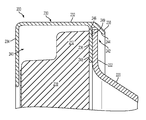
- FIG. 2 shows a cross-sectional side view of a portion of another exemplary radome-reflector assembly 200 of the disclosure.
- FIG. 2 shows a rim 230 retaining the periphery of radome 210 onto the periphery 222 of reflector 220 .
- Rim 230 has the following features or elements:
- the first and second rim legs 234 and 236 and the intervening portion of the rim body 232 form a first cavity 240 for receiving the periphery 212 of the radome 210 .
- the second and third rim legs 236 and 238 and the intervening portion of the rim body 232 form a second cavity 242 for receiving the periphery 222 of the reflector 220 .
- the third rim leg 238 has a slanted or angled inner surface 244 facing the interior of the second cavity 242 .
- the rim 230 is designed such that, as the rim is forced radially (down in FIG. 2 ) relative to the radome 210 and the reflector 220 , the slanted inner surface 244 of the third rim leg 238 engages with the periphery 222 of the reflector to force the reflector 220 laterally towards the second rim leg 236 to physically abut with the second rim leg to form a metal-to-metal RF seal.
- the second rim leg 236 has an outer, recessed portion 246 and an inner, unrecessed portion 248 , such that a clearance gap 249 exists between the recessed portion 246 and the corresponding outer edge region of the periphery 222 of the reflector 220 , when the corresponding inner edge region of the periphery of the reflector abuts the unrecessed portion 248 of the second rim leg.
- This clearance gap 249 helps to ensure a good RF seal between the reflector 220 and the rim 230 when contaminants like paint and/or metal burrs exist on that outer edge region of the periphery of the reflector, which contaminants could otherwise prevent that good RF seal in the absence of such a clearance gap.
- FIGS. 3(A) and 3(B) respectively show perspective and cut-away side views of an exemplary fixed clamp 350 used to secure two ends of two rims 330 retaining a radome 310 onto the periphery of a reflector 320 .
- FIGS. 3(C) and 3(D) respectively show corresponding exploded, perspective views from above and from below.
- fixed clamp 350 is a unitary structure made, e.g., of molded plastic.
- Fixed clamp 350 has keyed features 352 that fit within and slide forward to engage with two corresponding, mirror-image, keyed openings 331 in the circumferential bodies 332 of the two rims 330 to lock the fixed clamp in place, thereby securing the two ends of the two rims together.
- Fixed clamp 350 also has a cover portion 354 that limits exposure of the gap 333 between the two rims 330 to inhibit UV radiation and/or moisture from reaching the interior of the resulting radome-reflector assembly.
- fixed clamp 350 can include a moisture drain path for when it is fitted at the bottom of the radome-reflector assembly.
- FIGS. 4(A) and 4(B) respectively show perspective and cut-away side views of an exemplary adjustable clamp 370 used to secure the other two ends of the two rims 330 of FIG. 3 retaining the radome 310 onto the periphery of the reflector 320 .
- FIGS. 4(C) and 4(D) respectively show corresponding exploded, perspective views from above and from below.
- Adjustable clamp 370 has the following four elements:
- the mirror-image, keyed openings 331 in the two rims 330 receive corresponding keyed features 372 on the bottoms of the male and female components 376 and 378 .
- female component 378 has a cover portion 374 that limits exposure of the gap 335 between the two rims 330 to inhibit UV radiation and/or moisture from reaching the interior of the resulting radome-reflector assembly.
- the male component 376 may have a cover portion in addition to or instead of the female component 378 . Further embodiments may involve two (e.g., identical) components that do not have covers and do not engage as do male and female components.
- adjustable clamp 370 can include a moisture drain path for when it is fitted at the bottom of the radome-reflector assembly. Note that the nut 382 sits within a recess in the female component 378 that is shaped and sized to prevent the nut from rotating while the engaged screw 380 is rotated.
- adjustable clamp 370 may be pre-assembled at a relatively loose setting (e.g., screw 380 within the corresponding holes in the male and female components 376 and 378 , but with the nut 382 engaged near the threaded end of the screw 380 ).
- a relatively loose setting e.g., screw 380 within the corresponding holes in the male and female components 376 and 378 , but with the nut 382 engaged near the threaded end of the screw 380 ).
- the pre-assembled adjustable clamp 370 may be inserted into the corresponding openings 331 at the other two ends of the rims.
- the screw 380 can then be rotated to tighten the adjustable clamp 370 , thereby reducing the size of gap 335 between the ends of the two rims 330 .
- the adjustable clamp 370 is tightened, the periphery of the reflector 320 will be forced laterally against the second rim legs (not shown in FIG. 4 ) of the two rims 330 to form a good metal-to-metal RF seal between the metal rims and the metal reflector.
- each rim 330 is mirror images, such that both rims 330 are identical to one another, simply rotated radially 180 degrees from one another.
- the corresponding keyed features 352 and 372 of the fixed and adjustable clamps 350 and 370 are identical such that either clamp can be used at either the top or the bottom of the radome-reflector assembly (as top and bottom are depicted in the view of FIG. 1 ).
- two rims 330 could be secured to one another at both pairs of ends using two fixed clamps 350 or two adjustable clamps 370 , instead of one of each.
- the screw is inserted from the male component 376 into the female component 378 , and the nut resides within the female component.
- the screw hole in the second component is threaded to engage the screw or a self-tapping screw may be used with an un-threaded hole, such that the nut may be omitted.
- a ratchet-based mechanism may be employed to move the male and female components together over inter-locking serrated edges, such that both the nut and the screw may be omitted.
- FIGS. 5 and 6 respectively show another exemplary set of fixed and adjustable clamps 550 and 570 that can be used to secure two rims 530 together to form another exemplary radome-reflector assembly of the disclosure.
- FIG. 5(A) shows a perspective view of the fixed clamp 550 (e.g., a pressed stainless steel bracket) used to secure two ends of the two rims 530 retaining a radome 510 onto the periphery of a reflector (not shown in FIG. 5 , but labeled as 520 in FIG. 6(C) ), while FIGS. 5(B) and 5(C) respectively show corresponding exploded, perspective views of the fixed clamp 550 from above and from below.
- FIGS. 5(A) shows a perspective view of the fixed clamp 550 (e.g., a pressed stainless steel bracket) used to secure two ends of the two rims 530 retaining a radome 510 onto the periphery of a reflector (not shown in FIG. 5 ,
- FIG. 6(A) and 6(B) respectively show perspective and cut-away side views of the adjustable clamp 570 used to secure the other two ends of the two rims 530 retaining the radome 510 onto the periphery of the reflector 520
- FIG. 6(C) shows a corresponding exploded, perspective view from above.
- rims 530 have identical, mirror-image sets of openings 531 at their two ends which receive corresponding features 552 and 572 of either the fixed clamp 550 or the adjustable clamp 570 .
- openings 531 forceably receive features 552 of fixed clamp 550 .
- Fixed clamp 550 also has a curved edge feature 556 that engages with features (not shown) of the two rims 530 (e.g., analogous to the third rim leg 238 of rim 230 of FIG. 2 ) to secure the fixed clamp 550 in place.
- Adjustable clamp 570 has two identical components 577 (e.g., pressed stainless steel brackets) that are secured together using a screw 580 and a nut 582 .
- the fixed clamp 550 and (pre-assembled) adjustable clamp 570 can be used to assemble a radome-reflector assembly having a good metal-to-metal RF seal in a manner similar to the manner described earlier using fixed and adjustable clamps 350 and 370 of FIGS. 3 and 4 .
- FIGS. 7 and 8 respectively show yet another exemplary set of fixed and adjustable clamps 750 and 770 that can be used to secure two rims 730 together to form another exemplary radome-reflector assembly of the disclosure.
- FIGS. 7(A) and 7(B) respectively show perspective and cut-away side views of the fixed clamp 750 used to secure two ends of the two rims 730 retaining a radome 710 onto the periphery of a reflector (not shown in FIGS. 7 and 8 ).
- FIGS. 7(A) and 7(B) respectively show perspective and cut-away side views of the fixed clamp 750 used to secure two ends of the two rims 730 retaining a radome 710 onto the periphery of a reflector (not shown in FIGS. 7 and 8 ).
- FIG. 8(A) and 8(B) respectively show perspective and cross-sectional side views of the adjustable clamp 770 used to secure the other two ends of the two rims 730 retaining the radome 710 onto the periphery of the reflector, while FIG. 6(C) shows a perspective view of one end of one rim 730 .
- each rim 730 has an integral, stamped bracket or flange 777 having an opening (i.e., hole) 779 .
- fixed clamp 750 has two opposing, resilient, barbed arms 753 that deflect when fixed clamp 750 is forced over a pair of mated flanges 777 of the two rims 730 and then un-deflect when the barbed ends of arms 753 reach the openings in the flanges 777 to lock the fixed clamp 750 in place, thereby securing the ends of the two rims together.
- adjustable clamp 770 which involves inserting a screw 780 into the openings in the corresponding flanges 777 and securing the screw in place using a nut 782 .
- the screw-and-nut assembly can be adjusted to control the connecting force used to secure the rims together and form a good metal-to-metal RF seal between the reflector and the rims 730 as described previously.
- FIG. 9(A) shows a perspective, partial view of another exemplary pair of metal rims 930 for another exemplary radome-reflector assembly of the disclosure.
- FIG. 9(B) shows a cross-sectional side view of each of the rims 930 .
- each rim 930 has the following four elements:
- the second rim leg need not be shorter than the first rim leg.
- the first and second rim legs 934 and 936 and the intervening portion of the rim body 932 form a first cavity 940 for receiving the periphery 912 of a radome 910 and an (optional) RF absorber gasket 914 .
- an analogous RF absorber gasket could be included within the first cavity 240 of rim 230 of radome-reflector assembly 200 .
- the second and third rim legs 936 and 938 and the intervening portion of the rim body 932 form a second cavity 942 for receiving the periphery 922 of a metal reflector 920 .
- the rim 930 is designed such that, as the rim is forced radially (down in FIG. 9(B) ) relative to the radome 910 and the reflector 920 , the slanted, inner surface 944 of the third rim leg 938 engages with the periphery 922 of the reflector to force the reflector laterally towards the second rim leg 936 to physically abut the second rim leg to form a metal-to-metal RF seal.
- the second rim leg 936 of rim 930 may have a recessed portion to form a clearance gap in order to accommodate contaminants on the outer edge region of the reflector 920 similar to that of rim 230 of FIG. 2 .
- the U-shaped crimp portion 943 of the third rim leg 938 is designed to forceably receive and be crimped around a (e.g., threaded) press-fit, joining piece 990 to secure the two rims 930 together in a manner similar to that described in the '991 publication.
- a (e.g., threaded) press-fit, joining piece 990 to secure the two rims 930 together in a manner similar to that described in the '991 publication.
- Another identical joining piece 990 would also be used to secure the other two ends of the rims 930 together.
- the rim-based mechanisms of the present disclosure may provide one or more of the following additional advantages over the rim-based mechanism of the '991 publication in assembling radome-reflector assemblies.
- the amount of circumferential connecting force applied to certain rims of the present disclosure in order to form a good RF seal may be less than the corresponding connecting force applied per the '991 publication.
- corresponding radome-reflector assemblies of the present disclosure can be assembled without the use of relatively large clamping fixtures.
- certain radome-reflector assemblies of the present disclosure can be assembled in the field without requiring the use of any clamping fixtures or other special tooling.
- the lighter circumferential connecting force reduces the risk of physically distorting the shape of the reflector, thereby avoiding antenna performance degradation that might otherwise result from such physical distortion.
- the lighter circumferential connecting force also enables the fixed and adjustable clamps to be made of molded or pressed plastic or low-cost metal.
- certain radome-reflector assemblies of the present disclosure do not require frequency-specific backlobe suppression rings, opening the opportunity to produce assemblies having broader frequency bands of operation.
- the clamps and rims are designed such that the clamps sit relatively low within openings in the rims, where the circumferential connecting force applied by the clamps (e.g., the screw and nut) is substantially at the same radial distance from the center points of the radome and the reflector as the rim body elements.
- the clamps e.g., the screw and nut
- Such a configuration limits torquing forces that can otherwise bend the clamp components, further enabling them to be made of plastic or low-cost metal.
- the resulting low profiles of the clamping mechanisms also keeps the overall sizes of the resulting radome-reflector assemblies small, which reduces packing costs.
- assemblies may have more than two rims or just a single rim.
- each pair of adjacent rims could be interconnected using either a fixed clamp or an adjustable clamp.
- at least one pair of adjacent clamps are interconnected using an adjustable clamp.
- the substantially circular rim would have a gap such that the two ends of the rim would be bridged by a clamp that would be applied/tightened after the rim was twisted around the periphery of the radome and the sub-assembly then applied to the periphery of the reflector.
- the clamp is an adjustable clamp. It is also possible to have a hinged rim assembly consisting of two or more rims interconnected by one or more hinges, where the hinged rim assembly would have one or more gaps that would be bridged by one or more corresponding, fixed or adjustable clamps.
- One common feature of the embodiments of the present disclosure described above is the existence of a slanted inner surface on the third rim leg that forces the reflector laterally against the second rim leg to form a good RF seal when circumferential connecting force is applied by an adjustable clamp securing two ends of the rims together.
- Another common feature is that the peripheries of the radome and the reflector are received within different rim cavities.
- figure numbers and/or figure reference labels in the claims is intended to identify one or more possible embodiments of the claimed subject matter in order to facilitate the interpretation of the claims. Such use is not to be construed as necessarily limiting the scope of those claims to the embodiments shown in the corresponding figures.
Landscapes
- Physics & Mathematics (AREA)
- Electromagnetism (AREA)
- Details Of Aerials (AREA)
- Aerials With Secondary Devices (AREA)
Abstract
Description
-
- A semi-cylindrical,
circumferential rim body 232, supporting the other elements of the rim; - A first,
radial rim leg 234, extending perpendicularly from therim body 232 towards the center line of the semi-cylinder defined by the rim body; - A second,
radial rim leg 236, shorter than thefirst rim leg 234, but also extending perpendicularly from therim body 232 towards the semi-cylinder center line; and - A
third rim leg 238, shorter than thesecond rim leg 236 and extending from therim body 232 at about a 45-degree angle towards the semi-cylinder center line.
Note that, with reference toFIG. 1 , the analogous semi-cylinder center line referred to above intersects the center point ofradome 110 and the center point of the back end ofreflector 120. Although, in the embodiment ofFIG. 2 , thesecond rim leg 236 is shorter than thefirst rim leg 234, in alternative embodiments, the second rim leg may be the same size or even longer than the first rim leg. Furthermore, although, in the embodiment ofFIG. 2 , thethird rim leg 238 extends from therim body 232 at an angle of about 45 degrees, in general, any suitable angle that provides the desired functionality is acceptable.
- A semi-cylindrical,
-
- A
male component 376; - A
female component 378 having arecess 379 that receives a corresponding portion of the male component; - A threaded
screw 380 that fits within corresponding holes in the male and female components; and - A threaded
nut 382 that engages with the threaded end of the screw.
- A
-
- A semi-cylindrical,
circumferential rim body 932, supporting the other elements of the rim; - A first,
radial rim leg 934, extending perpendicularly from therim body 932 towards the center line of the semi-cylinder defined by the rim body; - A second,
radial rim leg 936, shorter than thefirst rim leg 934, but also extending perpendicularly from therim body 932 towards the semi-cylinder center line; and - A
third rim leg 938, having a U-shaped “crimp”portion 943 and a slanted,inner surface 944.
- A semi-cylindrical,
Claims (9)
Priority Applications (4)
| Application Number | Priority Date | Filing Date | Title |
|---|---|---|---|
| US14/247,307 US9577323B2 (en) | 2014-03-07 | 2014-04-08 | Radome—reflector assembly mechanism |
| EP14825045.9A EP3114731B1 (en) | 2014-03-07 | 2014-12-18 | Radome - reflector assembly mechanism |
| PCT/US2014/071074 WO2015134086A1 (en) | 2014-03-07 | 2014-12-18 | Radome - reflector assembly mechanism |
| US15/412,244 US10490888B2 (en) | 2014-03-07 | 2017-01-23 | Radome-reflector assembly mechanism |
Applications Claiming Priority (2)
| Application Number | Priority Date | Filing Date | Title |
|---|---|---|---|
| US201461949383P | 2014-03-07 | 2014-03-07 | |
| US14/247,307 US9577323B2 (en) | 2014-03-07 | 2014-04-08 | Radome—reflector assembly mechanism |
Related Child Applications (1)
| Application Number | Title | Priority Date | Filing Date |
|---|---|---|---|
| US15/412,244 Division US10490888B2 (en) | 2014-03-07 | 2017-01-23 | Radome-reflector assembly mechanism |
Publications (2)
| Publication Number | Publication Date |
|---|---|
| US20160294050A1 US20160294050A1 (en) | 2016-10-06 |
| US9577323B2 true US9577323B2 (en) | 2017-02-21 |
Family
ID=52302386
Family Applications (2)
| Application Number | Title | Priority Date | Filing Date |
|---|---|---|---|
| US14/247,307 Active 2035-08-18 US9577323B2 (en) | 2014-03-07 | 2014-04-08 | Radome—reflector assembly mechanism |
| US15/412,244 Active 2034-11-12 US10490888B2 (en) | 2014-03-07 | 2017-01-23 | Radome-reflector assembly mechanism |
Family Applications After (1)
| Application Number | Title | Priority Date | Filing Date |
|---|---|---|---|
| US15/412,244 Active 2034-11-12 US10490888B2 (en) | 2014-03-07 | 2017-01-23 | Radome-reflector assembly mechanism |
Country Status (3)
| Country | Link |
|---|---|
| US (2) | US9577323B2 (en) |
| EP (1) | EP3114731B1 (en) |
| WO (1) | WO2015134086A1 (en) |
Cited By (2)
| Publication number | Priority date | Publication date | Assignee | Title |
|---|---|---|---|---|
| US10158169B1 (en) | 2017-08-01 | 2018-12-18 | Winegard Company | Mobile antenna system |
| US20230198137A1 (en) * | 2021-12-16 | 2023-06-22 | The Boeing Company | Radome with ceramic matrix composite |
Families Citing this family (2)
| Publication number | Priority date | Publication date | Assignee | Title |
|---|---|---|---|---|
| USD825434S1 (en) | 2016-06-30 | 2018-08-14 | Barzan Holdings QSTP LLC | Aircraft radome |
| US11575213B2 (en) * | 2016-09-23 | 2023-02-07 | Commscope Technologies Llc | Antenna cover and methods of retention |
Citations (14)
| Publication number | Priority date | Publication date | Assignee | Title |
|---|---|---|---|---|
| US7042407B2 (en) | 2003-08-14 | 2006-05-09 | Andrew Corporation | Dual radius twist lock radome and reflector antenna for radome |
| US7138958B2 (en) | 2004-02-27 | 2006-11-21 | Andrew Corporation | Reflector antenna radome with backlobe suppressor ring and method of manufacturing |
| FR2908393A1 (en) | 2006-11-14 | 2008-05-16 | Safpac Soc Par Actions Simplif | Stirrup for maintaining end wall i.e. cover, has dorsal wall extended towards base, under lower side wall, via tab whose external face is curved for forming deflector, where free end of reflector is supported on external surface of shaft |
| US20090295677A1 (en) | 2008-05-27 | 2009-12-03 | Dish Network L.L.C. | Securing ring and assemblies |
| US20110140983A1 (en) * | 2009-12-11 | 2011-06-16 | Andrew Llc | Reflector Antenna Radome Attachment Band Clamp |
| US8077113B2 (en) | 2009-06-12 | 2011-12-13 | Andrew Llc | Radome and shroud enclosure for reflector antenna |
| US20130002515A1 (en) * | 2009-12-11 | 2013-01-03 | Andrew Llc | Radome Attachment Band Clamp |
| US8405570B2 (en) | 2010-05-27 | 2013-03-26 | Andrew Llc | Segmented antenna reflector with shield |
| US20130082896A1 (en) | 2011-09-29 | 2013-04-04 | Andrew Llc | Folded Tab Retention Twin Wall Radome and Method of Manufacture |
| US20130099991A1 (en) | 2011-10-24 | 2013-04-25 | Andew Llc | Method and Apparatus for Radome and Reflector Dish Interconnection |
| EP2615688A1 (en) | 2010-09-07 | 2013-07-17 | Comba Telecom System (China) Ltd. | Microwave antenna and its outer cover |
| US8558746B2 (en) | 2011-11-16 | 2013-10-15 | Andrew Llc | Flat panel array antenna |
| US8581795B2 (en) | 2011-09-01 | 2013-11-12 | Andrew Llc | Low sidelobe reflector antenna |
| EP2494651B1 (en) | 2010-10-11 | 2013-12-11 | Andrew LLC | Selectable Coupling Level Waveguide Coupler |
Family Cites Families (4)
| Publication number | Priority date | Publication date | Assignee | Title |
|---|---|---|---|---|
| US2481531A (en) * | 1945-07-11 | 1949-09-13 | Benjamin Electric Mfg Co | Fitting for lighting fixtures |
| US3351947A (en) * | 1965-02-17 | 1967-11-07 | Mark Products Company | Shrouded parabolic antenna structure |
| US8654035B2 (en) * | 2009-06-25 | 2014-02-18 | Avl Technologies, Inc. | Reflector latching mechanism for segmented reflectors used in satellite communication systems |
| EP2815688A1 (en) | 2013-06-21 | 2014-12-24 | Whirlpool Corporation | Domestic appliance, particularly clothes dryer, washing machine or dishwashing machine |
-
2014
- 2014-04-08 US US14/247,307 patent/US9577323B2/en active Active
- 2014-12-18 WO PCT/US2014/071074 patent/WO2015134086A1/en not_active Ceased
- 2014-12-18 EP EP14825045.9A patent/EP3114731B1/en active Active
-
2017
- 2017-01-23 US US15/412,244 patent/US10490888B2/en active Active
Patent Citations (15)
| Publication number | Priority date | Publication date | Assignee | Title |
|---|---|---|---|---|
| US7042407B2 (en) | 2003-08-14 | 2006-05-09 | Andrew Corporation | Dual radius twist lock radome and reflector antenna for radome |
| US7138958B2 (en) | 2004-02-27 | 2006-11-21 | Andrew Corporation | Reflector antenna radome with backlobe suppressor ring and method of manufacturing |
| FR2908393A1 (en) | 2006-11-14 | 2008-05-16 | Safpac Soc Par Actions Simplif | Stirrup for maintaining end wall i.e. cover, has dorsal wall extended towards base, under lower side wall, via tab whose external face is curved for forming deflector, where free end of reflector is supported on external surface of shaft |
| US20090295677A1 (en) | 2008-05-27 | 2009-12-03 | Dish Network L.L.C. | Securing ring and assemblies |
| US8077113B2 (en) | 2009-06-12 | 2011-12-13 | Andrew Llc | Radome and shroud enclosure for reflector antenna |
| US8259028B2 (en) | 2009-12-11 | 2012-09-04 | Andrew Llc | Reflector antenna radome attachment band clamp |
| US20110140983A1 (en) * | 2009-12-11 | 2011-06-16 | Andrew Llc | Reflector Antenna Radome Attachment Band Clamp |
| US20130002515A1 (en) * | 2009-12-11 | 2013-01-03 | Andrew Llc | Radome Attachment Band Clamp |
| US8405570B2 (en) | 2010-05-27 | 2013-03-26 | Andrew Llc | Segmented antenna reflector with shield |
| EP2615688A1 (en) | 2010-09-07 | 2013-07-17 | Comba Telecom System (China) Ltd. | Microwave antenna and its outer cover |
| EP2494651B1 (en) | 2010-10-11 | 2013-12-11 | Andrew LLC | Selectable Coupling Level Waveguide Coupler |
| US8581795B2 (en) | 2011-09-01 | 2013-11-12 | Andrew Llc | Low sidelobe reflector antenna |
| US20130082896A1 (en) | 2011-09-29 | 2013-04-04 | Andrew Llc | Folded Tab Retention Twin Wall Radome and Method of Manufacture |
| US20130099991A1 (en) | 2011-10-24 | 2013-04-25 | Andew Llc | Method and Apparatus for Radome and Reflector Dish Interconnection |
| US8558746B2 (en) | 2011-11-16 | 2013-10-15 | Andrew Llc | Flat panel array antenna |
Non-Patent Citations (2)
| Title |
|---|
| International Search Report and Written Opinion; Mailed Mar. 25, 2015 for the corresponding PCT Application No. PCT/US2014/071074. |
| Notification Concerning Transmittal of International Preliminary Report on Patentability, International Application No. PCT/US2014/071074, Date of mailing Sep. 22, 2016, 10 pages. |
Cited By (4)
| Publication number | Priority date | Publication date | Assignee | Title |
|---|---|---|---|---|
| US10158169B1 (en) | 2017-08-01 | 2018-12-18 | Winegard Company | Mobile antenna system |
| US20230198137A1 (en) * | 2021-12-16 | 2023-06-22 | The Boeing Company | Radome with ceramic matrix composite |
| US11901619B2 (en) * | 2021-12-16 | 2024-02-13 | The Boeing Company | Radome with ceramic matrix composite |
| US12407091B2 (en) * | 2021-12-16 | 2025-09-02 | The Boeing Company | Radome with ceramic matrix composite |
Also Published As
| Publication number | Publication date |
|---|---|
| US20160294050A1 (en) | 2016-10-06 |
| US10490888B2 (en) | 2019-11-26 |
| EP3114731A1 (en) | 2017-01-11 |
| WO2015134086A1 (en) | 2015-09-11 |
| EP3114731B1 (en) | 2020-07-15 |
| US20170133755A1 (en) | 2017-05-11 |
Similar Documents
| Publication | Publication Date | Title |
|---|---|---|
| US10490888B2 (en) | Radome-reflector assembly mechanism | |
| US5782499A (en) | Clamp for joining tubular pipe sections | |
| US9568130B2 (en) | Profiled clamp with sealing element | |
| CN103982497B (en) | Profile clamp with pre-determined bit device | |
| US9634400B2 (en) | Dish antenna having a self-supporting sub-reflector assembly | |
| US11454156B2 (en) | Exhaust clamp and method | |
| US10962156B2 (en) | Hose clamp | |
| US9151421B2 (en) | Profiled clamp | |
| KR20150051990A (en) | Coupling having gasket pocket of varying depth | |
| US9662795B2 (en) | Cover attachment structure for robot and robot having the same | |
| CN103875123A (en) | Method and apparatus for radome and reflector dish interconnection | |
| JP2018526592A (en) | Block joint and seal structure | |
| CA2882448C (en) | Ear clamp | |
| US10161551B2 (en) | Quick-connector | |
| CN111936780B (en) | Clamp apparatus | |
| FR2711753A1 (en) | Composite brake disc ventilated from the inside. | |
| US7387518B2 (en) | Grounding attachment assembly | |
| KR101740997B1 (en) | Cable restrain device with dual-material double wedge chuck | |
| TW200716891A (en) | O-ring and clamp-type joint for vacuum apparatus | |
| US20040247381A1 (en) | Spring clip with a u-shaped profile for flange connections | |
| WO1995026480A1 (en) | Apparatus for attachment of pipes | |
| EP1245892A1 (en) | Gasket | |
| JP2023517981A (en) | Installation of ceramic rollers in roller hearth furnaces | |
| RU98122512A (en) | PIPE FLANGE CONNECTION | |
| CA3300130A1 (en) | Pipe clamp, pipe clamp assembly and method for fastening the same |
Legal Events
| Date | Code | Title | Description |
|---|---|---|---|
| AS | Assignment |
Owner name: ANDREW LLC, NORTH CAROLINA Free format text: ASSIGNMENT OF ASSIGNORS INTEREST;ASSIGNORS:RENILSON, IAN T.;CURRAN, JOHN S.;HUNTER, DOUGLAS P.;AND OTHERS;REEL/FRAME:032623/0686 Effective date: 20140408 |
|
| AS | Assignment |
Owner name: COMMSCOPE TECHNOLOGIES LLC, NORTH CAROLINA Free format text: CHANGE OF NAME;ASSIGNOR:ANDREW LLC;REEL/FRAME:035226/0385 Effective date: 20150301 |
|
| AS | Assignment |
Owner name: WILMINGTON TRUST, NATIONAL ASSOCIATION, AS COLLATERAL AGENT, CONNECTICUT Free format text: SECURITY INTEREST;ASSIGNORS:ALLEN TELECOM LLC;COMMSCOPE TECHNOLOGIES LLC;COMMSCOPE, INC. OF NORTH CAROLINA;AND OTHERS;REEL/FRAME:036201/0283 Effective date: 20150611 Owner name: WILMINGTON TRUST, NATIONAL ASSOCIATION, AS COLLATE Free format text: SECURITY INTEREST;ASSIGNORS:ALLEN TELECOM LLC;COMMSCOPE TECHNOLOGIES LLC;COMMSCOPE, INC. OF NORTH CAROLINA;AND OTHERS;REEL/FRAME:036201/0283 Effective date: 20150611 |
|
| STCF | Information on status: patent grant |
Free format text: PATENTED CASE |
|
| AS | Assignment |
Owner name: ALLEN TELECOM LLC, NORTH CAROLINA Free format text: RELEASE OF SECURITY INTEREST PATENTS (RELEASES RF 036201/0283);ASSIGNOR:WILMINGTON TRUST, NATIONAL ASSOCIATION;REEL/FRAME:042126/0434 Effective date: 20170317 Owner name: COMMSCOPE TECHNOLOGIES LLC, NORTH CAROLINA Free format text: RELEASE OF SECURITY INTEREST PATENTS (RELEASES RF 036201/0283);ASSIGNOR:WILMINGTON TRUST, NATIONAL ASSOCIATION;REEL/FRAME:042126/0434 Effective date: 20170317 Owner name: COMMSCOPE, INC. OF NORTH CAROLINA, NORTH CAROLINA Free format text: RELEASE OF SECURITY INTEREST PATENTS (RELEASES RF 036201/0283);ASSIGNOR:WILMINGTON TRUST, NATIONAL ASSOCIATION;REEL/FRAME:042126/0434 Effective date: 20170317 Owner name: REDWOOD SYSTEMS, INC., NORTH CAROLINA Free format text: RELEASE OF SECURITY INTEREST PATENTS (RELEASES RF 036201/0283);ASSIGNOR:WILMINGTON TRUST, NATIONAL ASSOCIATION;REEL/FRAME:042126/0434 Effective date: 20170317 |
|
| AS | Assignment |
Owner name: WILMINGTON TRUST, NATIONAL ASSOCIATION, AS COLLATE Free format text: PATENT SECURITY AGREEMENT;ASSIGNOR:COMMSCOPE TECHNOLOGIES LLC;REEL/FRAME:049892/0051 Effective date: 20190404 Owner name: JPMORGAN CHASE BANK, N.A., NEW YORK Free format text: ABL SECURITY AGREEMENT;ASSIGNORS:COMMSCOPE, INC. OF NORTH CAROLINA;COMMSCOPE TECHNOLOGIES LLC;ARRIS ENTERPRISES LLC;AND OTHERS;REEL/FRAME:049892/0396 Effective date: 20190404 Owner name: JPMORGAN CHASE BANK, N.A., NEW YORK Free format text: TERM LOAN SECURITY AGREEMENT;ASSIGNORS:COMMSCOPE, INC. OF NORTH CAROLINA;COMMSCOPE TECHNOLOGIES LLC;ARRIS ENTERPRISES LLC;AND OTHERS;REEL/FRAME:049905/0504 Effective date: 20190404 Owner name: WILMINGTON TRUST, NATIONAL ASSOCIATION, AS COLLATERAL AGENT, CONNECTICUT Free format text: PATENT SECURITY AGREEMENT;ASSIGNOR:COMMSCOPE TECHNOLOGIES LLC;REEL/FRAME:049892/0051 Effective date: 20190404 |
|
| MAFP | Maintenance fee payment |
Free format text: PAYMENT OF MAINTENANCE FEE, 4TH YEAR, LARGE ENTITY (ORIGINAL EVENT CODE: M1551); ENTITY STATUS OF PATENT OWNER: LARGE ENTITY Year of fee payment: 4 |
|
| AS | Assignment |
Owner name: WILMINGTON TRUST, DELAWARE Free format text: SECURITY INTEREST;ASSIGNORS:ARRIS SOLUTIONS, INC.;ARRIS ENTERPRISES LLC;COMMSCOPE TECHNOLOGIES LLC;AND OTHERS;REEL/FRAME:060752/0001 Effective date: 20211115 |
|
| AS | Assignment |
Owner name: OUTDOOR WIRELESS NETWORKS LLC, NORTH CAROLINA Free format text: ASSIGNMENT OF ASSIGNORS INTEREST;ASSIGNOR:COMMSCOPE TECHNOLOGIES LLC;REEL/FRAME:068107/0089 Effective date: 20240701 |
|
| MAFP | Maintenance fee payment |
Free format text: PAYMENT OF MAINTENANCE FEE, 8TH YEAR, LARGE ENTITY (ORIGINAL EVENT CODE: M1552); ENTITY STATUS OF PATENT OWNER: LARGE ENTITY Year of fee payment: 8 |
|
| AS | Assignment |
Owner name: JPMORGAN CHASE BANK, N.A., AS COLLATERAL AGENT, NEW YORK Free format text: PATENT SECURITY AGREEMENT (TERM);ASSIGNOR:OUTDOOR WIRELESS NETWORKS LLC;REEL/FRAME:068770/0632 Effective date: 20240813 Owner name: JPMORGAN CHASE BANK, N.A., AS COLLATERAL AGENT, NEW YORK Free format text: PATENT SECURITY AGREEMENT (ABL);ASSIGNOR:OUTDOOR WIRELESS NETWORKS LLC;REEL/FRAME:068770/0460 Effective date: 20240813 |
|
| AS | Assignment |
Owner name: APOLLO ADMINISTRATIVE AGENCY LLC, NEW YORK Free format text: SECURITY INTEREST;ASSIGNORS:ARRIS ENTERPRISES LLC;COMMSCOPE TECHNOLOGIES LLC;COMMSCOPE INC., OF NORTH CAROLINA;AND OTHERS;REEL/FRAME:069889/0114 Effective date: 20241217 |
|
| AS | Assignment |
Owner name: OUTDOOR WIRELESS NETWORKS LLC, NORTH CAROLINA Free format text: RELEASE OF SECURITY INTEREST AT REEL/FRAME 068770/0632;ASSIGNOR:JPMORGAN CHASE BANK, N.A., AS COLLATERAL AGENT;REEL/FRAME:069743/0264 Effective date: 20241217 Owner name: RUCKUS WIRELESS, LLC (F/K/A RUCKUS WIRELESS, INC.), NORTH CAROLINA Free format text: RELEASE OF SECURITY INTEREST AT REEL/FRAME 049905/0504;ASSIGNOR:JPMORGAN CHASE BANK, N.A., AS COLLATERAL AGENT;REEL/FRAME:071477/0255 Effective date: 20241217 Owner name: COMMSCOPE TECHNOLOGIES LLC, NORTH CAROLINA Free format text: RELEASE OF SECURITY INTEREST AT REEL/FRAME 049905/0504;ASSIGNOR:JPMORGAN CHASE BANK, N.A., AS COLLATERAL AGENT;REEL/FRAME:071477/0255 Effective date: 20241217 Owner name: COMMSCOPE, INC. OF NORTH CAROLINA, NORTH CAROLINA Free format text: RELEASE OF SECURITY INTEREST AT REEL/FRAME 049905/0504;ASSIGNOR:JPMORGAN CHASE BANK, N.A., AS COLLATERAL AGENT;REEL/FRAME:071477/0255 Effective date: 20241217 Owner name: ARRIS SOLUTIONS, INC., NORTH CAROLINA Free format text: RELEASE OF SECURITY INTEREST AT REEL/FRAME 049905/0504;ASSIGNOR:JPMORGAN CHASE BANK, N.A., AS COLLATERAL AGENT;REEL/FRAME:071477/0255 Effective date: 20241217 Owner name: ARRIS TECHNOLOGY, INC., NORTH CAROLINA Free format text: RELEASE OF SECURITY INTEREST AT REEL/FRAME 049905/0504;ASSIGNOR:JPMORGAN CHASE BANK, N.A., AS COLLATERAL AGENT;REEL/FRAME:071477/0255 Effective date: 20241217 Owner name: ARRIS ENTERPRISES LLC (F/K/A ARRIS ENTERPRISES, INC.), NORTH CAROLINA Free format text: RELEASE OF SECURITY INTEREST AT REEL/FRAME 049905/0504;ASSIGNOR:JPMORGAN CHASE BANK, N.A., AS COLLATERAL AGENT;REEL/FRAME:071477/0255 Effective date: 20241217 |
|
| AS | Assignment |
Owner name: OUTDOOR WIRELESS NETWORKS LLC, NORTH CAROLINA Free format text: PARTIAL TERMINATION AND RELEASE OF SECURITY INTEREST IN PATENTS RECORDED AT REEL 069889/FRAME 0114;ASSIGNOR:APOLLO ADMINISTRATIVE AGENCY LLC;REEL/FRAME:070154/0341 Effective date: 20250131 Owner name: OUTDOOR WIRELESS NETWORKS LLC, NORTH CAROLINA Free format text: PARTIAL TERMINATION AND RELEASE OF SECURITY INTEREST IN PATENTS;ASSIGNOR:U.S. BANK TRUST COMPANY, NATIONAL ASSOCIATION;REEL/FRAME:070154/0183 Effective date: 20250131 Owner name: OUTDOOR WIRELESS NETWORKS LLC, NORTH CAROLINA Free format text: RELEASE (REEL 068770 / FRAME 0460);ASSIGNOR:JPMORGAN CHASE BANK, N.A.;REEL/FRAME:070149/0432 Effective date: 20250131 |