US956565A - Leather-compressing mechanism for shoe-finishing machines. - Google Patents
Leather-compressing mechanism for shoe-finishing machines. Download PDFInfo
- Publication number
- US956565A US956565A US51601709A US1909516017A US956565A US 956565 A US956565 A US 956565A US 51601709 A US51601709 A US 51601709A US 1909516017 A US1909516017 A US 1909516017A US 956565 A US956565 A US 956565A
- Authority
- US
- United States
- Prior art keywords
- leather
- rolls
- end frames
- compressing mechanism
- shoe
- Prior art date
- Legal status (The legal status is an assumption and is not a legal conclusion. Google has not performed a legal analysis and makes no representation as to the accuracy of the status listed.)
- Expired - Lifetime
Links
Images
Classifications
-
- A—HUMAN NECESSITIES
- A43—FOOTWEAR
- A43D—MACHINES, TOOLS, EQUIPMENT OR METHODS FOR MANUFACTURING OR REPAIRING FOOTWEAR
- A43D35/00—Presses for shaping pre-existing loose soles, shoe bottoms or soles fixed to shoe bottoms
Definitions
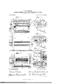
- Figure 1 is a vertical front view of part of the frame and driving mechanism of shoe finishing machine provided with my improved leather compressing mechanism.
- a leather compressing mechanism comprising hollow end frames, journal blocks supported in horizontal guide ways in the end frames, front and back rolls rotatably supported in the ournal blocks, screw threaded shafts screw threaded through the end frames and butting against the front ournal blocks, sprocket wheels on the shafts, a sprocket chain connecting the sprocket wheels, a handle on the right sprocket wheel, springs en aging with the journal blocks to automatically hold the rolls in an open adjusted position, heavy springs engaging with the journal blocks of the back roll, means for adjusting the tension of the heavy springs, stops on the end frames to limit the forward movement of the back roll, means for revolving the rolls and means forming a mouth in the top of the mechanism to feed leather to the rolls by gravity.
Landscapes
- Treatment And Processing Of Natural Fur Or Leather (AREA)
Description
H, B. BORNSIDE. LEATHER COMEEESSING MECHANISM FOR SE03 FINISEING MACHINES.
APPLIGATION FILED SE? IN'YE'NTUH.
llllllfi 55 ml: tllalllilllflfllulm WITNEEEEE.
UNITED STATES PATENT QFFICE.
HARRY BENJAMIN BORNSIDE, OF PROVIDENCE, RHODE ISLAND.
LEATHER-COMPRESSING MECHANISM FOR SHOE-FINISHING MACHINES.
To all whom it may concern:
Be it known that l, HARRY BENJAMIN BOBNSIDE, a citizen of the United States, residing at Providence, in the county of Providence and State of Rhode Island, have invented a new and useful Improvement in Leather-Compressing Mechanisms for Shoe- Finishing Machines, of which the following is a specification.
This invention has reference to an improvement in leather working machines and more particularly to an improvement in leather compressing mechanism for shoe finishing machines.
The object of my invention is to improve the construction of a leather compressing mechanism whereby the mechanism is adapted for use in shoe finishing machines and the pieces of leather, which are usually shoe taps or sole blanks are fed to the compressing rolls by gravity, thereby eliminating the usual method which requires that the pieces of leather be held and fed to the rolls by hand.
A further object of my invention is to construct a leather compressing mechanism so that the compressing rolls are automatically held in any open adjusted position, thereby facilitating the automatic feeding of the leather to the rolls.
rlnother object of my invention is to construct a leather compressing mechanism so that the same may be secured to and form a part of a shoe finishing machine and 00- cupy space not heretofore utilized by the operative parts of the machine.
Another object of my invention is to construct a leather compressing mechanism so that by the addition of a frame and driving mechanism the compressing mechanism may be used as a separate and complete machine, for compressing or rolling leather.
A final object of my invention is to sim plify the construction of a leather compressing mechanism thereby reducing the cost of manufacturing the same.
My invention consists in the peculiar and novel construction of a leather compressing mechanism for shoe finishing machines said mechanism having details of construction, as will be more fully set forth hereinafter and claimed.
Figure 1. is a vertical front view of part of the frame and driving mechanism of shoe finishing machine provided with my improved leather compressing mechanism.
Specification of Letters Patent.
Application filed September 8, 1909.
Patented May 3, 1916..
Serial No. 516,017.
Fig. 2. is a top plan view of "Fig. 1. Fig. 3. is a transverse sectional view taken on line 3. of Fig. 1. Fig. 4. is a transverse sectional view taken on line 1. l. of Fig. 1. Fig. is a longitudinal detail sectional view taken vertically on a line drawn centrally through the pulleys and between the com pressing rolls. looking toward the front and 6. is an enlarged detail sectional view taken on a horizontal line drawn centrally through the left hand ournal blocks of the compressing rolls.
In the drawings (4 indicates the frame, 5 the main driving shaft, 0 the main driving pulley, (Z the upper front strut and e the upper back strut of a shoe finishing machine provided with my improved leather compressing mechanism which consists of hollow end frames 8. 8. supported on the front and back struts (Z and e to which they are secured. Each end frame 8. has a cavity 9. approximately the shape of the frame, as shown in Figs. 4. and 5, front and back horizontal guide-ways 10. and 11. in the end walls, the front edge of the back guide-way 11. forming a stop 12 as shown in Fig. Journal blocks 13. 13. in the guide-ways 10. and 11, a twin whip spring 14. held in the cavity 9. by a pin 15 intermediate the bearing blocks 10. and 11, in a position for the free ends of the spring to engage with the blocks, as shown in Fig. 4;. A. screwthreaded shaft 16. screw-threaded through the front of each frame 8. 8. on a centr al horizontal line with the journal blocks 13. 13., the inner end of each shaft butting against the front journal block 13., a sprocket wheel 17 secured to the outer end of each shaft 16. 16, a sprocket chain 18. connecting the sprocket wheels 17. 17. on the shafts 16. 16. and a handle 19. on the right hand sprocket wheel, as shown in Fig. 1. Brackets 20. 20. each bracket secured to the back of an end frame 8. and having a sleeve 21. extending through a hole in the end frame 8, a comparatively heavy coiled spring 22. in the sleeve 21 and engaging with the rear journal block 13., an adjusting bolt 23. screw-threaded through the bracket and engaging with the spring 22., and a downwardly and forwardly curved arm 24:. as shown in Fig. l. A curved sheet metal drip apron 25. secured at each end to the arms 24. 24c. and having a drip trough 26. at the front edge, each end of the trough being closed by a removable plug 27. An
inwardly extending downwardly curved plate 28. secured to the front strut (Z, an inwardly extending downwardly curved plate 29. secured to the back strut 6 each plate extending from the right to the left hand end frames 8. 8., the inner edges of the plates forming a central longitudinal slot 30, as shown in Figs. 2. and 3. A back roll 31. journaled in the rear journal blocks 13. 13. and having a gear 32. A front roll 33. journaled in the front journal blocks 13. 13. and having a gear 34. meshing with the gear 32 on the back roll and a gear 35 on the opposite end of the roll. A stud 36 secured to the left hand end frame 8., an idle pulley 37. on the stud, a pulley 38. on the stud and having a gear 39. meshing with the gear 35 on the front roll 33. A pulley 40 on the main driving shaft 6, a belt 11. connecting the pulley 10. with either of the pulleys 37 or 38. and a shipper lever 42 pivotally secured at its lower end to the frame of the machine and having a shipper as. engaging with the belt 11. The shipper lever 12. extends upward in a convenient position for the operator, as shown in Fig. 1.
The end frames 8. 8. and the plates 28 and 29. form a V shape mouth 44. in the top of the mechanism with the slot 30 directly above the opening between the rolls 31 and 33. as shown in Figs. 2. and 3. The rolls are adjusted or spaced for different thicknesses of leather by turning the handle 19, the twin whip springs 14:. 1 1. forcing the front journal blocks 13. 13. against the ends of the shafts 16. 16. and holding the rolls in an open position. The tension on the back roll 31. is adjusted by turning the adjusting bolts 23. 23. and the back roll is held in its normal forward position by the stops 12. 12. on the end frames 8. 8. Power is transmitted from the driving shaft 6 through the pulley 40. the belt 41., the pulley 38, the gear 39., the gear 35. and the gears 3A and 32. to revolve the rolls 33. and 31.
The rolls are quickly adjusted for any thickness of leather and when so adjusted the leather is simply dropped into the mouth 44 of the mechanism. The plates 28 and 29 now guide the leather which drops by gravity through the slot 30 and between the rolls 31. and 33. which squeeze or compress the leather. The leather now drops from the rolls on to the apron 25 and the moisture squeezed from the leather collects on the apron and drips into the drip pan 26. from which it is removed when required.
By the peculiar construction of the mouth 44. and the rolls being always held in an open adjusted position the leather is fed by gravity to the rolls, thereby eliminating the operation and time required of feeding the leather to the rolls by hand as has heretofore been done.
It is evident that the gear 35. may be secured to the back roll 31. and mesh with the gear 39. on the pulley 38, without materially affecting the spirit of my invention.
Having thus described my invention, I claim as new and desire to secure by Letters Patent 1. A leather compressing mechanism having end frames, rolls rotatably supported by the end frames, means for adjusting the position of the rolls relative to each other, means for revolving the rolls and means for feeding leather to the rolls by gravity.
2. A leather compressing mechanism having end frames, rolls rotatably supported by the end frames, means for adjusting the position of the rolls relative to each other, means for automatically holding the rolls in an open adjusted position, means for revolving the rolls and means for feeding leather to the rolls by gravity.
3. A leather compressing mechanism com prising end frames, rolls rotatably supported by the end frames, means for adjusting the rolls relative to each other, means for automatically holding the rolls in an open adjusted position, means for revolving the rolls and means forming a mouth in the top of the mechanism to feed leather by gravity to the rolls.
4. A leather compressing mechanism comprising end frames, front and back rolls rotatably supported in the end frames, means for adjusting the front roll relative to the back roll, springs intermediate the rolls adapted to automatically hold the rolls in an open adjusted position; means for exerting a spring tension on the back roll, means for adjusting the spring tension on the back roll, means for revolving the rolls and down wardly curved plates which with the end frames form a mouth in the top of the mechanism to feed leather by gravity to the rolls.
5. A leather compressing mechanism comprising end frames, journal blocks supported in horizontal guide ways in the end frames, front and back rolls rotatably supported in the journal blocks, means for adjusting the front roll relative to the back roll, springs intermediate and engaging with the journal blocks and adapted to automatically hold the rolls in an open adjusted position, heavy springs engaging with the journal blocks of the back roll, means for adjusting the tension of the heavy springs on the journal blocks, stops on the end frames engaging with the journal blocks of the back roll to limit the forward movement of the back roll, means for revolving the rolls and means forming a mouth in the top of the mechanism to feed leather by gravity to the rolls.
6. In combination, a leather compressing mechanism comprising hollow end frames, journal blocks supported in horizontal guide ways in the end frames, front and back rolls rotatably supported in the ournal blocks, screw threaded shafts screw threaded through the end frames and butting against the front ournal blocks, sprocket wheels on the shafts, a sprocket chain connecting the sprocket wheels, a handle on the right sprocket wheel, springs en aging with the journal blocks to automatically hold the rolls in an open adjusted position, heavy springs engaging with the journal blocks of the back roll, means for adjusting the tension of the heavy springs, stops on the end frames to limit the forward movement of the back roll, means for revolving the rolls and means forming a mouth in the top of the mechanism to feed leather to the rolls by gravity.
'7. In combination, a leather coi'npressing mechanism comprising hollow end frames, journal blocks supported in guide ways in the end frames, front and back rolls rotatably supported in the journal blocks,means engaging with the front journal blocks to adjust the front roll relative to the back roll, springs engaging with the journal blocks to automatically hold the rolls in an open adjusted position, heavy springs engaging with the journal blocks of the back roll, means for adjusting the tension of the heavy springs, brackets secured to the back of the end frames and having downwardly and forwardly curved arms, a drip apron secured to the arms, a drip trough on the forward edge of the apron, means for revolving the rolls and downwardly curved plates which with the end frames form a mouth in the top of the mechanism to feed leather by gravity to the rolls.
8. In combination, a leather compressing mechanism comprising hollow end frames, journal blocks supported in guide ways in the end frames, front and back rolls rotatably supported in the journal blocks, shafts screw-threaded through the end frames and engaging with the front ournal blocks, a sprocket wheel on each shaft, asprocket chain connecting the sprocket wheels, a handle on the right sprocket wheel, springs engaging with the journal blocks to automatically hold the rolls in an open adjusted position, heavy springs engaging with the journal blocks of the back roll, means for adjusting the tension of the heavy springs, brackets secured to the back of the end frames and having downwardly and forwardly curved arms, a drip apron secured to the arms, a drip trough on the forward edge of the drip apron, a gear on the back roll meshing with a gear on the front roll, a stud on the left hand end frame, an idle pulley on the stud, a pulley on the stud having a gear meshing with a gear on the front roll, means for revolving the pulley carrying the gear, means for shipping a belt from the idle pulley to the gear pulley and downwardly curved plates which with the end frames form a mouth in the top of the mechanism to feed leather by gravity to the rolls.
In testimony whereof, I have signed my name to this specification in the presence of two subscribing witnesses.
HARRY BENJAl HN BORNSIDE.
lVitnesses lrNTl-IONY V. Pnr'rmn, BENNIE OIANOIARULO.
Priority Applications (1)
| Application Number | Priority Date | Filing Date | Title |
|---|---|---|---|
| US51601709A US956565A (en) | 1909-09-03 | 1909-09-03 | Leather-compressing mechanism for shoe-finishing machines. |
Applications Claiming Priority (1)
| Application Number | Priority Date | Filing Date | Title |
|---|---|---|---|
| US51601709A US956565A (en) | 1909-09-03 | 1909-09-03 | Leather-compressing mechanism for shoe-finishing machines. |
Publications (1)
| Publication Number | Publication Date |
|---|---|
| US956565A true US956565A (en) | 1910-05-03 |
Family
ID=3024968
Family Applications (1)
| Application Number | Title | Priority Date | Filing Date |
|---|---|---|---|
| US51601709A Expired - Lifetime US956565A (en) | 1909-09-03 | 1909-09-03 | Leather-compressing mechanism for shoe-finishing machines. |
Country Status (1)
| Country | Link |
|---|---|
| US (1) | US956565A (en) |
-
1909
- 1909-09-03 US US51601709A patent/US956565A/en not_active Expired - Lifetime
Similar Documents
| Publication | Publication Date | Title |
|---|---|---|
| US2671992A (en) | Edge grinding machine for glass plates or the like | |
| US1642782A (en) | Machine for making corrugated paper | |
| US956565A (en) | Leather-compressing mechanism for shoe-finishing machines. | |
| US1096633A (en) | Box-folding machine. | |
| US106276A (en) | Improvement in machines for husking corn | |
| US1359357A (en) | Grinding-mill | |
| US430359A (en) | white | |
| US1138567A (en) | Feeding mechanism for carding-machines. | |
| US253565A (en) | August l | |
| US319991A (en) | Dough-rolling machine | |
| US555417A (en) | baron | |
| US245608A (en) | John j | |
| US2350381A (en) | Wringer | |
| US254969A (en) | Charles hemje | |
| US589782A (en) | janney | |
| US1327299A (en) | Paraffining-machine | |
| US726329A (en) | Machine for making shooks for boxes. | |
| US1183013A (en) | Planer and matcher. | |
| US858248A (en) | Pea-shelling machine. | |
| US138244A (en) | Improvement in planing-machines | |
| US1963865A (en) | Block feeder fok match machines | |
| US913869A (en) | Cigar-machine. | |
| US1651140A (en) | Metal-working machine | |
| US194171A (en) | Improvement in wringing-machines | |
| US1063779A (en) | Horseshoe-forming machine. |