US9565617B2 - Method and apparatus for configuring routing path in wireless communication system - Google Patents
Method and apparatus for configuring routing path in wireless communication system Download PDFInfo
- Publication number
- US9565617B2 US9565617B2 US14/072,087 US201314072087A US9565617B2 US 9565617 B2 US9565617 B2 US 9565617B2 US 201314072087 A US201314072087 A US 201314072087A US 9565617 B2 US9565617 B2 US 9565617B2
- Authority
- US
- United States
- Prior art keywords
- terminal
- neighboring
- intermediary
- target
- routing
- Prior art date
- Legal status (The legal status is an assumption and is not a legal conclusion. Google has not performed a legal analysis and makes no representation as to the accuracy of the status listed.)
- Expired - Fee Related, expires
Links
Images


Classifications
-
- H—ELECTRICITY
- H04—ELECTRIC COMMUNICATION TECHNIQUE
- H04W—WIRELESS COMMUNICATION NETWORKS
- H04W84/00—Network topologies
- H04W84/18—Self-organising networks, e.g. ad-hoc networks or sensor networks
-
- H—ELECTRICITY
- H04—ELECTRIC COMMUNICATION TECHNIQUE
- H04W—WIRELESS COMMUNICATION NETWORKS
- H04W40/00—Communication routing or communication path finding
- H04W40/02—Communication route or path selection, e.g. power-based or shortest path routing
- H04W40/20—Communication route or path selection, e.g. power-based or shortest path routing based on geographic position or location
-
- H—ELECTRICITY
- H04—ELECTRIC COMMUNICATION TECHNIQUE
- H04W—WIRELESS COMMUNICATION NETWORKS
- H04W40/00—Communication routing or communication path finding
- H04W40/24—Connectivity information management, e.g. connectivity discovery or connectivity update
- H04W40/28—Connectivity information management, e.g. connectivity discovery or connectivity update for reactive routing
Definitions
- the present disclosure relates to a wireless communication system. More particularly, the present disclosure relates to configuring a routing path between terminals.
- An ad-hoc wireless network is a type of a peer-to-peer mode for performing direct communication among a plurality of radio stations without the aid of an access point or other wired network connections.
- the ad-hoc wireless network is useful since a wireless network can be configured rapidly and easily in a place where a wireless infrastructure does not exist.
- a routing path is configured by selecting an intermediary node (or an intermediary terminal) between a source terminal and a target terminal (or a destination terminal) on the basis of a routing algorithm.
- Most of well-known routing algorithms aim to select a minimum number of intermediary nodes between the source terminal and the target terminal.
- a routing path having the minimum number of intermediary nodes is not necessarily an optimal routing path.
- the intermediary node between the source terminal and the target terminal is located at an edge of a coverage region of the source terminal, there is a disadvantage in that the routing path, which transmits data, may be broken due to a movement of the source terminal or the intermediary node.
- a routing path formed with a relatively large number of intermediary nodes between the source terminal and the target terminal disadvantageously leads to an increase in an amount of power consumed among the plurality of intermediary nodes.
- a Location-Aided Routing (LAR) algorithm is a representative routing algorithm which uses location information selected from among well-known routing algorithms.
- the LAR is an algorithm for determining an expected zone in which the target terminal can move at an average speed during a unit time and a request zone in which the source terminal must transmit a message according to the expected zone, and for selecting an intermediary terminal within the request zone.
- the LAR disadvantageously delivers many messages unnecessarily since the source terminal transmits and receives a message for configuring a routing path with respect to all terminals in the request zone.
- an aspect of the present disclosure is to provide a method and apparatus for configuring a routing path which uses location information of a terminal in a wireless communication system.
- Another aspect of the present disclosure is to provide a method and apparatus for configuring a routing path by using a linear virtual line which reaches from a source terminal to a target terminal in a wireless communication system.
- Yet another aspect of the present disclosure is to provide a method and apparatus for determining a point at which a virtual line and an orthogonal line cross by using a line which is from an intermediary terminal and which is orthogonal to the virtual line between a source terminal and a target terminal, and for selecting the intermediary terminal by using a distance to the point with respect to the source terminal in a wireless communication system.
- Still another aspect of the present disclosure is to provide a method and apparatus for determining a region excluded in a selection of an intermediary node on the basis of a maximum speed of a terminal and for selecting a neighboring terminal not included in the region excluded in the selection of the intermediary node as the intermediary terminal in a wireless communication system.
- Still another aspect of the present disclosure is to provide a method and apparatus for configuring a routing path in such a manner that, if a response message for a path configuration is received from a terminal in a wireless communication, it is determined whether the terminal which transmits the response message is identical to a terminal determined as a previous node.
- a method of a node selecting terminal for configuring a routing path includes measuring a first distance between the terminal and a target terminal, transmitting information of the measured first distance to at least one neighboring terminal, receiving a second distance measured for the target terminal with respect to the terminal from the at least one neighboring terminal, and determining a neighboring terminal of which the second distance is the longest as a next terminal of the routing path.
- a method of a neighboring terminal for configuring a routing path includes receiving from a node selecting terminal a signal including a first distance between the node selecting terminal and a target terminal, determining whether the target terminal is the neighboring terminal, when the target terminal is not the neighboring terminal, measuring a second distance to the target terminal on the basis of the node selecting terminal by using the distance information, and transmitting the second distance to the node selecting terminal.
- a node selecting terminal for configuring a routing path.
- the node selecting terminal includes a transceiver configured to transmit and receive a signal with at least one neighboring terminal, and a controller configured to control a function for measuring a first distance between the node selecting terminal and a target terminal, to transmit the measured distance information to the at least one neighboring terminal, to receive a second distance measured for the target terminal with respect to the terminal from the at least one neighboring terminal, and to determine a neighboring terminal of which the second distance is the longest as a next terminal of the routing path.
- a neighboring terminal for configuring a routing path.
- the neighboring terminal includes a transceiver configured to transmit and receiving a signal with at least one different terminal, and a controller configured to control a function of receiving from a node selecting terminal a signal including a first distance between the node selecting terminal and a target terminal, to determine whether the target terminal is the neighboring terminal, and if the target terminal is not the neighboring terminal, to measure a second distance to the target terminal on the basis of the node selecting terminal by using the distance information and to transmit the second distance to the node selecting terminal.
- FIG. 1 illustrates a projection line and a shadow line according to an embodiment of the present disclosure
- FIGS. 2A, 2B, and 2C illustrate an example of configuring a routing path on the basis of a projection line and a shadow line according to an embodiment of the present disclosure
- FIG. 3A and FIG. 3B illustrate a signal flow for configuring a routing path between a source terminal and a target terminal according to an embodiment of the present disclosure
- FIG. 4 illustrates a region excluded in selection of an intermediary node according to an embodiment of the present disclosure
- FIG. 5A and FIG. 5B illustrate a process of a source terminal for configuring a routing path according to an embodiment of the present disclosure
- FIGS. 6A, 6B, and 6C illustrate a process of an intermediary terminal for configuring a routing path according to an embodiment of the present disclosure
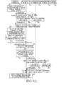
- FIG. 7 is a flowchart illustrating a process of a target terminal for configuring a routing path according to an embodiment of the present disclosure
- FIG. 8 is a block diagram illustrating a structure of a terminal for configuring a routing path according to an embodiment of the present disclosure.
- FIG. 9 and FIG. 10 are graphs illustrating performance on a routing path configuration according to the related art and an embodiment of the present disclosure.
- an intermediary node, an intermediary terminal, and a next terminal may equally refer to an intermediary node of a routing path, and these terms are interchangeably used in the following description.
- FIG. 1 illustrates a projection line and a shadow line according to an embodiment of the present disclosure.
- the present disclosure configures a routing path between the source terminal S 100 and the target terminal T 102 .
- the source terminal S 100 generates a virtual line (hereinafter, called a projection line) 121 which reaches to the target terminal 102 , and calculates a length of the projection line 121 .
- the length of the projection line 121 can be calculated on the basis of location information of the source terminal S 100 and location information of the target terminal T 102 .
- the length of the projection line 121 can be calculated as shown in Equation (1) on the basis of a coordinate (X S , Y S , Z S ) indicating a location of the source terminal S 100 and a coordinate (X T , Y T , Z T ) indicating a location of the target terminal T 102 .
- PROJ S ⁇ square root over ( ⁇ X T ⁇ X S ⁇ 2 + ⁇ Y T ⁇ Y S ⁇ 2 + ⁇ Z T ⁇ Z S ⁇ 2 ) ⁇ Equation (1)
- PROJ S denotes a length of the projection line between the source terminal S 100 and the target terminal T 102 .
- a terminal 111 neighboring to the source terminal S 100 generates a virtual line 123 orthogonal to the projection line 121 between the source terminal S 100 and the target terminal T 102 , and calculates a distance of a line 127 (hereinafter, called a shadow line) connecting the source terminal S 100 at a point 125 at which the projection line 121 and the virtual line 123 intersect.
- the shadow line can indicate a relative distance of a neighboring terminal to the target terminal T 102 , measured with respect to the source terminal S 100 .
- the distance of the shadow line 127 can be calculated on the basis of a projection distance, a distance between the source terminal S 100 and the neighboring terminal A 111 , and a distance between the target terminal T 102 and the neighboring terminal A 111 .
- the distance of the shadow line 127 can be calculated by Equation (2) below.
- SHAD A DIST S 2 - DIST T 2 + PROJ S 2 2 ⁇ PROJ S Equation ⁇ ⁇ ( 2 )
- SHAD A denotes a length of the shadow line 127 of the neighboring terminal A 111
- DIST S denotes a distance between the neighboring terminal A 111 and the target terminal T 102
- PROJ S denotes a length of the projection line 121 which reaches from the source terminal S 100 to the target terminal 102 .
- the length of the shadow line may be a positive number or a negative number.
- a neighboring terminal of which a shadow line has a greatest distance is selected as a terminal for performing a role of an intermediary node. That is, according to the embodiment of the present disclosure, from among a plurality of neighboring terminals capable of receiving a signal from the source terminal S 100 , a neighboring terminal closest in distance to the target terminal T 102 may be selected as an intermediary terminal.
- the intermediary terminal repeatedly generates a projection line which reaches to the target terminal T 102 , may calculate a length of the projection line, may calculate the length of the shadow line on the basis of the calculated length of the projection line as described above, and may select a next intermediary terminal.
- FIGS. 2A, 2B and 2C illustrate an example of configuring a routing path on the basis of a projection line and a shadow line according to an embodiment of the present disclosure.
- each terminal may change in location due to a movement.
- a source terminal S 100 generates a projection line 120 which reaches from the source terminal S 100 to a target terminal T 102 , and transmits length information of the projection line 120 to neighboring terminals 111 , 114 , and 116 . Then, upon receiving the length information of the projection line 120 , the neighboring terminals 111 , 114 , and 116 respectively calculate lengths of shadow lines 121 , 122 , and 123 for the projection line 120 , and transmit length information of the shadow lines 121 , 122 , and 123 to the source terminal S 100 .
- the source terminal S 100 selects the terminal A 111 having a longest shadow line to a next node, i.e., an intermediary terminal, and reports to the terminal A 111 that it is selected as the intermediary terminal.
- a next node i.e., an intermediary terminal
- the terminal A 111 selected as the intermediary terminal generates a projection line 130 which reaches from the terminal A 111 to the target terminal T 102 , and transmits length information of the projection line 130 to neighboring terminals 112 , 113 , and 116 . Then, upon receiving the length information of the projection line 130 , the neighboring terminals 112 , 113 , and 116 respectively calculate lengths of shadow lines 131 , 132 , and 133 for the projection line 130 , and transmit length information of the shadow lines 131 , 132 , and 133 to the terminal A 111 .
- the terminal C 113 selects the terminal A 111 having a longest shadow line to a next node, i.e., an intermediary terminal, and reports to the terminal C 113 that it is selected as the intermediary terminal.
- the terminal C 113 selected as the intermediary terminal generates a projection line 140 which reaches from the terminal C 113 to the target terminal T 102 , and transmits length information of the projection line 140 to neighboring terminals 102 , 111 , 112 , and 115 . Since the target terminal T 102 exists in a coverage region of the terminal C 113 , a signal for configuring a routing path can be received from the terminal C 113 . Accordingly, the target terminal T 102 transmits a response signal to the terminal C 113 selected as the intermediary node. This response signal is delivered to the source terminal S 100 via the terminal A 111 and the terminal C 113 selected as the intermediary node, and thus a routing path is configured between the source terminal S 110 and the target terminal T 102 .
- FIG. 3A and FIG. 3B illustrate a signal flow for configuring a routing path between a source terminal and a target terminal according to an embodiment of the present disclosure.
- a source terminal 100 calculates a projection line which reaches from the source terminal 100 to a target terminal 102 .
- the source terminal 100 transmits to neighboring terminals 111 and 112 a Query-Routing Request (Q-RREQ) message including the calculated length of the projection line.
- the Q-RREQ message includes an IDentifier (ID) and location information (or a location coordinate) of a terminal for transmitting the Q-RREQ message, an ID and location information of a target terminal, and a length of a projection line which reaches from the terminal for transmitting the Q-RREQ message to the target terminal.
- ID IDentifier
- location information or a location coordinate
- the Q-RREQ message transmitted by the source terminal S 100 includes an ID of the source terminal S 100 , location information of the source terminal S 100 , an ID of the target terminal T 102 , location information of the target terminal T 102 , and length information of the projection line 120 which reaches from the source terminal S 100 to the target terminal T 102 .
- each of the neighboring terminal A 111 and the neighboring terminal B 112 calculates a length of a shadow line by using projection line length information of the source terminal 100 .
- the neighboring terminal A 111 confirms length information of the projection line 120 , location information of the source terminal S 100 , and location information of the target terminal T 102 from the Q-RREQ message, then calculates a distance between the source terminal S 100 and the neighboring terminal A 111 and a distance between the target terminal T 102 and the neighboring terminal A 111 , and then calculates a length of the shadow line 121 by using Equation (2).
- each of the neighboring terminal A 111 and the neighboring terminal B 112 transmits to the source terminal T 100 an Acknowledgement-Routing Request (A-RREQ) message including the calculated length of the shadow line.
- the A-RREQ message includes an ID and location information of a terminal for transmitting the Q-RREQ message, an ID and location information of a terminal for transmitting the A-RREQ message, and the calculated length of the shadow line. For example, referring to FIG.
- the A-RREQ message transmitted by the terminal A 111 in response to the Q-RREQ of the source terminal S 100 includes an ID of the source terminal S 100 , location information of the source terminal S 100 , an ID of the neighboring terminal A 111 , location information of the neighboring terminal A 111 , and the length information of the shadow line 121 calculated in the neighboring terminal A 111 .
- the source terminal S 100 determines a red zone, and selects a neighboring terminal having an optimal shadow line as a next terminal (or an intermediary terminal) of a routing path on the basis of the determined red zone.
- the red zone is a region which is included in a coverage region of the terminal for selecting the intermediary node and which is excluded in selection of the intermediary node, and is determined as a region having a high probability that the routing path can be broken in next data transmission by considering a speed of the terminal. That is, a region within a coverage region (or a region corresponding to the maximum transmission radius) of a terminal for selecting an intermediary node can be divided into an intermediary node non-selection region and an intermediary node selection region.
- the red zone is determined on the basis of a maximum transmission radius of a terminal for selecting an intermediary node and a maximum speed of the terminal as shown in Equation (3) below.
- R RED (d) denotes a radius of an intermediary node selection region, and is used as a distance for determining a red zone.
- R denotes a maximum transmission radius of a terminal for selecting an intermediary node.
- r denotes a terminal movement radius per a unit time, and is determined by a terminal's maximum movement speed v max and a unit time t.
- the remaining regions other than a region corresponding to R RED (d) determined according to Equation (3) are determined as a red zone 410 which is excluded in selection of an intermediary node.
- a neighboring terminal located in the red zone does not break the routing path in the present disclosure, it is regarded that the routing path can be broken at a next time point due to a movement of the terminal, and thus the neighboring terminal located in the red zone is excluded from a node selection target.
- FIG. 4 illustrates a region excluded in selection of an intermediary node according to an embodiment of the present disclosure.
- the source terminal 100 can select the terminal A 111 , and not the terminal B 112 , as a next node of a routing path even if a length of a shadow line of the terminal B 112 is longer than a length of a shadow line of the terminal A 111 .
- the source terminal 100 can select the terminal A 111 , and not the terminal B 112 , as a next node of a routing path even if a length of a shadow line of the terminal B 112 is longer than a length of a shadow line of the terminal A 111 .
- a region not corresponding to a maximum transmission radius of the source terminal 100 for selecting an intermediary node is excluded from an intermediary node selection target region. Therefore, a terminal D 114 , which is located out of the maximum transmission radius of the source terminal 100 for selecting the intermediary node, is also excluded from the intermediary node selection target.
- a region indicating a movement radius of a neighboring terminal can be directly calculated in each neighboring terminal and then can be transmitted to an intermediary node selecting terminal.
- an intermediary node can be calculated in the selecting terminal.
- the region indicating the movement radius of the neighboring terminal can be calculated as shown in Equation (4) below according to a distance between the neighboring terminal and the terminal for selecting the intermediary node.
- a 1 ⁇ r 2 ⁇ ( v max ⁇ t ) 2 ,0 ⁇ d ⁇ R ⁇ r
- a 2 ⁇ 1 R 2 + ⁇ 2 r 2 ⁇ d ⁇ sin ⁇ 2 ,R ⁇ r ⁇ d ⁇ R+r
- a 3 0, R+r ⁇ d Equation (4)
- r denotes a terminal movement radius per a unit time, and is determined by terminal's maximum movement speed v max and a unit time t.
- R denotes a maximum transmission radius of a terminal for selecting an intermediary node
- d denotes a distance between the source terminal S 100 for selecting an intermediary node and a neighboring terminal.
- ⁇ 1 is
- the source terminal S 100 determines neighboring terminals which have a region other than a red zone as a movement radius region from among regions corresponding to a maximum transmission radius of the intermediary terminal A 111 each as being a candidate intermediary terminal, and selects a terminal having a longest shadow line as a next terminal (or an intermediary terminal) from among the candidate intermediary terminals.
- the neighboring terminal A 111 is selected as the next terminal between the neighboring terminal A 111 and the neighboring terminal B 112 .
- the source terminal S 100 writes information of the terminal A 111 selected as the next terminal in a routing table.
- the routing table can include a source terminal ID, a target terminal ID, a previous terminal ID, and a next terminal ID. In this case, since a previous terminal of the source terminal S 100 does not exist, it can be written that the previous terminal ID does not exist.
- the source terminal S 100 transmits to the neighboring terminal A 111 a Decision-Routing Request (D-RREQ) message indicating that it is selected as an intermediary terminal.
- the D-RREQ message includes an ID and location information (or a location coordinate) of the terminal S 110 for transmitting the D-RREQ message and an ID and location information of the terminal A 111 selected as the intermediary terminal.
- the terminal A 111 selected as the intermediary terminal writes information on a routing path to its routing table.
- the routing table can include a source terminal ID, a target terminal ID, a previous terminal ID, and a next terminal ID.
- the terminal A 111 can write to its routing table an ID of the terminal S 100 as an ID of a source terminal, an ID of the terminal T 102 as an ID of a target terminal, and an ID of the source terminal S 100 as an ID of a previous terminal.
- the intermediary terminal A 111 calculates a length of a projection line which reaches from the intermediary terminal A 111 to the target terminal 102 .
- the intermediary terminal A 111 transmits a Q-RREQ message including the calculated length of the projection line to the neighboring terminals 112 and 113 .
- the Q-RREQ message transmitted by the intermediary terminal A 111 includes an ID of the intermediary terminal A 111 , location information of the intermediary terminal A 111 , an ID of the target terminal T 102 , location information of the target terminal T 102 , and length information of the projection line 130 which reaches from the intermediary terminal A 111 to the target terminal T 102 .
- the neighboring terminal B 112 and the neighboring terminal C 113 calculate a length of a shadow line by using projection line length information of the intermediary terminal A 111 .
- the neighboring terminal B 112 confirms length information of the projection line 130 , location information of the intermediary terminal A 111 , and location information of the target terminal T 102 from the Q-RREQ message, thereafter calculates a distance between the intermediary terminal A 111 and the neighboring terminal B 112 and a distance between the target terminal T 102 and the neighboring terminal B 112 , and thereafter calculates a length of the shadow line 131 as illustrated in Equation (2).
- the neighboring terminal B 112 and the neighboring terminal C 113 transmit an A-RREQ message including the calculated length of the shadow line to the intermediary terminal A 111 .
- the A-RREQ message includes an ID and location information of a terminal which transmits the Q-RREQ message, an ID and location information of a terminal which transmits the A-RREQ message, and the calculated length of the shadow line.
- the A-RREQ message transmitted by the terminal B 112 in response to the Q-RREQ of the intermediary terminal A 111 includes an ID of the intermediary terminal A 111 , location information of the intermediary terminal A 111 , an ID of the neighboring terminal B 112 , location information of the neighboring terminal B 112 , and length information of the shadow line 131 calculated in the neighboring terminal B 112 .
- the intermediary terminal A 111 Upon receiving the A-RREQ message from the neighboring terminals 112 and 114 , in operation 325 , the intermediary terminal A 111 determines a red zone, and selects a neighboring terminal having an optimal shadow line as a next terminal (or an intermediary terminal) of a routing path on the basis of the determined red zone.
- the red zone is a region which is included in a coverage of the terminal A for selecting the intermediary node and which is excluded in selection of the intermediary node, and is determined as a region having a high probability that the routing path can be broken in next data transmission by considering a speed of the terminal That is, the intermediary terminal A 111 determines neighboring terminals, which have a region other than a red zone as a movement radius region from among regions corresponding to a maximum transmission radius of the intermediary terminal A 111 , as a candidate intermediary terminal on the basis of the red zone determined by using Equation (3) and a region indicating a movement radius of each neighboring terminal determined by Equation (4), and thereafter selects a terminal having a longest shadow line as a next terminal (or an intermediary terminal) from among the candidate intermediary terminals.
- the neighboring terminal C 113 is selected as the next terminal between the neighboring terminal B 112 and the neighboring terminal C 113 .
- the intermediary terminal A 111 writes information of the terminal C 113 selected as the next terminal in the routing table.
- the intermediary terminal A 111 additionally writes an ID of the next terminal, i.e., an ID of the terminal C 113 , in the routing table written in the aforementioned operation 315 .
- the intermediary terminal A 111 transmits to the neighboring terminal C 113 a D-RREQ message indicating that it is selected as the intermediary terminal.
- the D-RREQ message includes an ID and location information (or a location coordinate) of the terminal A 111 for transmitting the D-RREQ message and an ID and location information of the terminal C 113 selected as the intermediary terminal.
- the terminal C 113 selected as the intermediary terminal writes information on a routing path to its routing table.
- the routing table can include a source terminal ID, a target terminal ID, a previous terminal ID, and a next terminal ID.
- the terminal C 113 can write to its routing table an ID of the terminal A 111 as an ID of a source terminal, an ID of the terminal T 102 as an ID of a target terminal, and an ID of the source terminal S 100 as an ID of a previous terminal.
- the intermediary terminal C 113 calculates a length of a projection line which reaches from the intermediary terminal C 113 to the target terminal 102 .
- the intermediary terminal C 113 transmits a Q-RREQ message including a length of a projection line to neighboring terminals.
- the Q-RREQ message transmitted by the intermediary terminal C 113 includes an ID of the intermediary terminal C 113 , location information of the intermediary terminal C 113 , an ID of the target terminal T 102 , location information of the target terminal T 102 , and length information of the projection line 140 which reaches from the intermediary terminal C 113 to the target terminal T 102 .
- the target terminal T 102 which receives the Q-RREQ message confirms that its own ID is identical to an ID of a target terminal of the received Q-RREQ message, determines whether the received Q-RREQ message is for configuring a routing path of the source terminal S 100 and the target terminal T 102 .
- the target terminal T 102 writes the intermediary terminal C 113 which transmits the Q-RREQ to a routing table.
- the routing table may include a source terminal ID, a target terminal ID, a previous terminal ID, and a next terminal ID.
- the target terminal T 102 may write to its own routing table an ID of the terminal S 100 as an ID of a source terminal, an ID of the terminal T 102 as an ID of a target terminal, and the intermediary terminal C 113 as an ID of a previous terminal. In this case, since the target terminal T 102 is a final destination of data transmitted by the source terminal S 100 , it may be written that the next terminal does not exist.
- the target terminal T 102 transmits a Routing Response (RREP) message to the intermediary terminal C 113 which is a previous terminal.
- the RREP message may include an ID of a source terminal, location information of the source terminal, an ID of a target terminal, and location information of the target terminal.
- the intermediary terminal C 113 which receives the RREP message writes a next terminal as the target terminal T 102 . That is, the intermediary terminal C 113 may additionally write the ID of the target terminal T 102 to an ID of a next terminal of the routing table written in operation 321 .
- the intermediary terminal C 113 confirms the previous terminal's ID written in the routing table and delivers the RREP message to the intermediary terminal A 111 , which is a previous terminal.
- the intermediary terminal A 111 confirms an ID of a terminal which transmits the RREP message.
- the intermediary terminal A compares an ID of the terminal which transmits the RREP message with a next terminal's ID written in the routing table. If the ID of the terminal C 113 which transmits the RREP message is not identical to the next terminal's ID written in the routing table, then the intermediary terminal A 111 determines that an error occurs in the routing path, and returning to operation 319 , repeats an operation for selecting the next terminal again.
- the intermediary terminal A 111 determines the terminal C 113 as a next terminal of the intermediary terminal A 111 .
- the intermediary terminal A 111 confirms the previous terminal's ID written in the routing table.
- the intermediary terminal A 111 delivers the RREP message to the source terminal S 100 which is a previous terminal.
- the source terminal S 100 which receives the RREP message confirms an ID of a terminal which transmits the RREP message.
- the source terminal S 100 compares an ID of the terminal which transmits the RREP message with a next terminal's ID written in the routing table. If the ID of the terminal A 111 which transmits the RREP message is not identical to the next terminal's ID written in the routing table, the source terminal S 100 determines that an error occurs in the routing path, and returning to operation 303 , repeats an operation for selecting the next terminal again.
- the source terminal S 100 determines the terminal A 111 as a next terminal, and determines that the configuration of the routing path is complete. Next, the source terminal S 100 transmits data, which is to be transmitted to the target terminal T 102 , through the routing path.
- intermediary terminals of the routing path may have only information of a previous terminal which will receive data and a next terminal which will transmit data, without having to have information on the entirety of the routing path.
- FIG. 5A and FIG. 5B illustrate a process of a source terminal for configuring a routing path according to an embodiment of the present disclosure.
- the source terminal calculates a length of a projection line which reaches from the source terminal to a target terminal.
- the length of the projection line can be calculated as shown in Equation (1) by using location information (or a coordinate) of the source terminal and location information of the target terminal.
- the source terminal transmits a Q-RREQ message including the length of the projection line to neighboring terminals.
- the Q-RREQ message includes an ID and location information (or a location coordinate) of the source terminal, an ID and location information of the target terminal, and the length of the projection line which reaches from the source terminal to the target terminal.
- the source terminal determines whether an A-RREQ message is received from at least one neighboring terminal within a pre-set Time to Live (TTL). If the A-RREQ is not received from the at least one neighboring terminal within the pre-set TTL, returning to operation 503 , the source terminal retransmits the Q-RREQ message.
- TTL Time to Live
- the source terminal confirms a shadow line value of a corresponding neighboring terminal, included in the received A-RREQ message.
- the source terminal determines a red zone indicating a region excluded in selection of an intermediary terminal.
- the source terminal determines a candidate intermediate terminal to neighboring terminals which are located within a maximum transmission radius of the source terminal from among neighboring terminals for transmitting the A-RREQ and which are not located in a region not corresponding to the red zone, and determines a next terminal (or an intermediary terminal) to be a terminal having a longest shadow line from among the candidate intermediary terminals.
- the red zone of the source terminal is determined by using a maximum transmission radius of the source terminal and a terminal movement radius per a unit time.
- the neighboring terminal is located within the maximum transmission radius of the source terminal and is not located in a region not corresponding to the red zone can be determined by using a region indicating a movement radius of each neighboring terminal as shown in Equation (4) above.
- the region indicating the movement radius of each neighboring terminal can be directly calculated in a corresponding neighboring terminal, and can also be calculated in the source terminal That is, the source terminal can divide a region corresponding to the maximum transmission radius of the source terminal into an intermediary terminal non-selection region (i.e., a red zone) and an intermediary terminal selection region, and can determine a candidate intermediary terminal to neighboring terminals located in the intermediary terminal selection region.
- the source terminal writes a next terminal in the routing table.
- the routing table of the source terminal can include a source terminal ID, a target terminal ID, a previous terminal ID, and a next terminal ID. In this case, since a previous terminal of the source terminal S 100 does not exist, it can be written that the previous terminal ID does not exist.
- the source terminal transmits to a next terminal a D-RREQ message indicating that it is selected as an intermediary terminal.
- the D-RREQ message includes an ID and location information (or a location coordinate) of the terminal for transmitting the D-RREQ message and an ID and location information of the neighboring terminal selected as the intermediary terminal.
- the source terminal determines whether an RREP message is received within a pre-set TTL. If the RREP message is not received within the pre-set TTL, the source terminal determines that the routing path is broken, and returning to operation 503 , retransmits the Q-RREQ message to neighboring terminals to re-select a next terminal.
- the pre-set TTL can be measured with respect to a time at which the D-RREQ message is transmitted, and can be set to a size different from that of the TTL in operation 505 .
- the source terminal determines whether a terminal which transmits the RREP message is identical to a next terminal written in the routing table. If the terminal which transmits the RREP message is not identical to the next terminal written in the routing table, the source terminal determines that the routing path is broken, and returning to operation 503 , retransmits the Q-RREQ message to neighboring terminals to re-select a next terminal.
- the source terminal determines that the configuration of the routing path is complete, and proceeding to operation 521 , transmits and receives data for the target terminal to and from the next terminal. In this case, the data transmitted to the next terminal is transmitted to the target terminal via the routing path.
- FIGS. 6A 6 B and 6 C illustrate a process of an intermediary terminal for configuring a routing path according to an embodiment of the present disclosure.
- the intermediary terminal receives a Q-RREQ message including a projection line length from an intermediary node selecting terminal.
- the intermediary terminal can receive the Q-RREQ message from a source terminal which intends to configure the rouging path, and can receive the Q-RREQ message from the intermediary terminal
- the terminal which transmits the Q-RREQ message is called the intermediary node selecting terminal.
- the intermediary terminal calculates a length of a shadow line by using projection line length information included in the Q-RREQ message.
- the length information of the shadow line can be calculated as shown in Equation (2) above by using projection line length information, a location of the intermediary node selecting terminal, and location information of the target terminal.
- the intermediary terminal transmits an A-RREQ message including the length of the shadow line to the intermediary node selecting terminal.
- the intermediary terminal determines whether a D-RREQ message is received within a pre-set TTL.
- the pre-set TTL can be measured with respect to an A-RREQ message transmission time. If the D-RREQ message is not received within the pre-set TTL, the procedure of FIG. 6 ends.
- the intermediary terminal determines that it is selected as the intermediary node.
- the intermediary terminal writes an intermediary node selecting terminal which transmits the D-RREQ message in the routing table as a previous terminal.
- the intermediary terminal writes a source terminal ID and a target terminal ID in the routing table.
- the intermediary terminal calculates a length of a projection line which reaches from the intermediary terminal to the target terminal on the basis of target terminal's location information included in the Q-RREQ message.
- the length of the projection line can be calculated as shown in Equation (1) by using location information (or a coordinate) of the intermediary terminal and location information of the target terminal.
- the intermediary terminal transmits a Q-RREQ message including the length of the projection line to neighboring terminals.
- the Q-RREQ message includes an ID and location information (or a location coordinate) of the intermediary terminal, an ID and location information of the target terminal, and the length of the projection line which reaches from the intermediary terminal to the target terminal.
- the Q-RREQ message can include an ID of the source terminal.
- the intermediary terminal determines whether an A-RREQ message is received from at least one neighboring terminal within a pre-set TTL. If the A-RREQ is not received from the at least one neighboring terminal within the pre-set TTL, the procedure proceeds to operation 627 .
- the intermediary terminal confirms a shadow line value of a corresponding neighboring terminal, included in the received A-RREQ message.
- the intermediary terminal determines a red zone indicating a region excluded in selection of an intermediary terminal.
- the intermediary terminal determines a candidate intermediate terminal to neighboring terminals which are located within a maximum transmission radius of the intermediary terminal from among neighboring terminals for transmitting the A-RREQ and which are not located in a region not corresponding to the red zone, and determines a next terminal (or an intermediary terminal) to a terminal having a longest shadow line from among the candidate intermediary terminals.
- the red zone of the intermediary terminal is determined by using a maximum transmission radius of the intermediary terminal and a terminal movement radius per a unit time.
- whether the neighboring terminal is located within the maximum transmission radius of the intermediary terminal and is not located in a region not corresponding to the red zone can be determined by using a region indicating a movement radius of each neighboring terminal as shown in Equation (4) above.
- the region indicating the movement radius of each neighboring terminal can be directly calculated in a corresponding neighboring terminal, and can also be calculated in the intermediary terminal.
- the intermediary terminal writes a next terminal in the routing table. That is, the intermediary terminal can additionally write a next terminal ID in the routing table written in the aforementioned operation 609 .
- the intermediary terminal transmits to the next terminal a D-RREQ message indicating that it is selected as the intermediary terminal.
- the D-RREQ message includes an ID and location information (or a location coordinate) of a terminal which transmits the D-RREQ message and an ID and location information of a neighboring terminal selected as the intermediary terminal.
- the D-RREQ message can include an ID of the source terminal.
- the intermediary terminal determines whether an RREP message is received within a pre-set TTL. If the RREP message is not received within the pre-set TTL, the intermediary terminal determines that the routing path is broken, and returning to operation 613 , retransmits the Q-RREQ message to neighboring terminals to re-select a next terminal.
- the pre-set TTL can be measured with respect to a time at which the D-RREQ message is transmitted, and can be set to a size different from that of the TTL in operation 615 .
- the intermediary terminal determines whether a terminal which transmits the RREP message is a target terminal. If it is the target terminal, directly proceeding to operation 633 , the intermediary terminal transmits a response message to a previous terminal written in the routing table. In this case, the intermediary terminal can write an ID of the target terminal in the routing table as an ID of a next terminal.
- the intermediary terminal determines whether a terminal which transmits the RREP message is identical to the next terminal written in the routing table. If the terminal which transmits the RREP message is not identical to the next terminal written in the routing table, the intermediary terminal determines that the routing path is broken, and returning to operation 613 , retransmits the Q-RREQ message to neighboring terminals to re-select a next terminal.
- the intermediary terminal determines that the configuration of the routing path is complete, and proceeding to operation 633 , transmits the RREP message to the previous terminal written in the routing table.
- the intermediary terminal determines whether data is received from the previous terminal or the next terminal. If the data is received, proceeding to operation 637 , the intermediary terminal delivers the data to the previous terminal or next terminal written in the routing table.
- FIG. 7 is a flowchart illustrating a process of a target terminal for configuring a routing path according to an embodiment of the present disclosure.
- the target terminal receives a Q-RREQ message including a projection line length from a neighboring terminal in operation 701 , and compares whether its ID is equal to a target terminal's ID included in the Q-RREQ message in operation 703 . If its ID is not identical to the target terminal's ID included in the Q-RREQ message, proceeding to operation 603 , the target terminal performs the subsequent steps.
- the target terminal If its ID is identical to the target terminal's ID included in the Q-RREQ message, proceeding to operation 705 , the target terminal transmits an RREP message to a corresponding neighboring terminal Thereafter, the target terminal and receives data from a source terminal to the neighboring terminal in operation 707 , and then the procedure of FIG. 7 ends.
- the target terminal can periodically transmit the RREP message to determine whether the routing path is maintained.
- the source terminal and intermediary terminals of the routing path can transmit a Routing Error (RRER) message to the next terminal to request retransmission of the RREP message, or can perform an operation for determining that an error occurs in the routing path and retransmitting a Q-RREQ message to reconfigure the routing path.
- RRER Routing Error
- FIG. 8 is a block diagram illustrating a structure of a terminal for configuring a routing path according to an embodiment of the present disclosure.
- the terminal includes a controller 800 , a transceiver 810 , and a storage unit 820 .
- the controller 800 includes a routing path controller 802 .
- the controller 800 controls and processes an overall operation of the terminal, and according to the present disclosure, includes the routing path controller 802 to control and process a function for configuring a routing path between a source terminal and a target terminal. That is, the routing path controller 802 includes a projection line calculator 804 to control and process a function for calculating a length of a projection line which reaches from a corresponding terminal to the target terminal if the terminal is a source terminal or an intermediary terminal, and for transmitting a Q-RREQ message including the calculated length of the projection line to neighboring terminals.
- the routing path controller 802 includes a red zone determining unit 806 to control and process a function for determining a red zone of a corresponding terminal if the terminal is a source terminal or an intermediary terminal, and for selecting a next terminal, i.e., a next intermediary terminal, of a routing path on the basis of the red zone and a region indicating a movement radius of a neighboring terminal.
- a red zone determining unit 806 to control and process a function for determining a red zone of a corresponding terminal if the terminal is a source terminal or an intermediary terminal, and for selecting a next terminal, i.e., a next intermediary terminal, of a routing path on the basis of the red zone and a region indicating a movement radius of a neighboring terminal.
- the routing path controller 802 receives an A-RREQ message from the neighboring terminal, determines a candidate intermediary terminal to neighboring terminals of which a movement radius region of a neighboring terminal overlaps with a region other than a red zone from among regions corresponding to a maximum transmission radius of the terminal, and selects a terminal having a longest shadow line as a next terminal from among the candidate intermediary terminals.
- the routing path controller 802 controls and processes a function for transmitting a D-RREQ message to a selected next terminal to report that it is selected as an intermediary node.
- the routing path controller 802 includes a shadow line calculation unit 808 to control and process a function for calculating a length of a shadow line upon receiving from a neighboring terminal a Q-RREQ message of which a target terminal is another terminal, and for transmitting an A-RREQ message including the calculated length of the shadow line to the terminal which transmits the Q-RREQ message.
- the routing path controller 802 controls and processes a function for transmitting an RREP message upon receiving a Q-RREQ message of which a target terminal is the terminal itself from the neighboring terminal.
- the routing path controller 802 controls and processes a function for writing information of a next terminal in a routing table 822 if the next terminal is selected, and for writing information of a previous terminal in the routing table if a D-RREQ is received from the neighboring table. That is, the routing path controller 802 controls and processes the functions described above in FIG. 3 to FIG. 7 .
- the transceiver 810 processes signal transmission and reception with respect to a neighboring terminal, a next terminal, a previous terminal, or a target terminal under the control of the controller 800 .
- the storage unit 820 stores data and various programs required for an operation of the terminal, and includes the routing table 822 according to the present disclosure.
- the routing table 822 is written by the routing path controller 802 , and if an error occurs in the routing path, can be updated by the routing path controller 802 .
- the routing table 822 may include an ID of a source terminal, an ID of a target terminal, an ID of a previous terminal, and an ID of a next terminal.
- the routing table 822 may include location information of the source terminal, location information of the target terminal, location information of the previous terminal, and location information of the next terminal.
- FIG. 9 and FIG. 10 are graphs illustrating performance on a routing path configuration according to the related art and an embodiment of the present disclosure.
- LAR denotes a Location-Aided Routing (LAR) algorithm described in the prior art
- TATR denotes a method proposed in the present disclosure.
- a horizontal axis represents a time at which a terminal temporarily stops its moving while the terminal moves
- a vertical axis represents a probability that a packet is successfully delivered. If a pause time of the terminal is within 0 to 40 seconds, it can be seen that the conventional LAR scheme has a higher packet delivery success rate that the TATR scheme of the present disclosure, whereas if the pause time of the terminal is greater than or equal to 60 seconds, the TATR scheme proposed in the present disclosure has a higher packet delivery success rate than the conventional LAR scheme.
- a horizontal axis represents a time at which a terminal temporarily stops its moving while the terminal moves
- a vertical axis represents the number of hops of a routing path.
- the TATR scheme of the present disclosure has an advantage in that the number of times of transmitting a control message for configuring a routing path can be decreased in comparison with the conventional LAR scheme.
- a routing path is configured by using a linear virtual line which reaches from a source terminal to a target terminal on the basis of location information of a terminal in a wireless communication, each terminal performs an independent computation without a complex computation process, and thus there is an advantage in that an optimal data routing path can be configured by using a minimum number of intermediary terminals.
- a region excluded in selection of an intermediary node is determined on the basis of a maximum speed of a terminal, and thereafter a terminal for taking a role of an intermediary node is selected from the remaining terminals other than a terminal capable of breaking a data routing path on the basis of the determined region excluded in selection of the intermediary node, thereby being able to configure a reliable routing path.
- the various embodiments of the present disclosure as described above typically involve the processing of input data and the generation of output data to some extent.
- This input data processing and output data generation may be implemented in hardware or software in combination with hardware.
- specific electronic components may be employed in a mobile device or similar or related circuitry for implementing the functions associated with the various embodiments of the present disclosure as described above.
- one or more processors operating in accordance with stored instructions may implement the functions associated with the various embodiments of the present disclosure as described above. If such is the case, it is within the scope of the present disclosure that such instructions may be stored on one or more non-transitory processor readable mediums.
- processor readable mediums examples include Read-Only Memory (ROM), Random-Access Memory (RAM), CD-ROMs, magnetic tapes, floppy disks, and optical data storage devices.
- ROM Read-Only Memory
- RAM Random-Access Memory
- CD-ROMs Compact Disc-ROMs
- magnetic tapes magnetic tapes
- floppy disks optical data storage devices.
- the processor readable mediums can also be distributed over network coupled computer systems so that the instructions are stored and executed in a distributed fashion.
- functional computer programs, instructions, and instruction segments for accomplishing the present disclosure can be easily construed by programmers skilled in the art to which the present disclosure pertains.
Landscapes
- Engineering & Computer Science (AREA)
- Computer Networks & Wireless Communication (AREA)
- Signal Processing (AREA)
- Mobile Radio Communication Systems (AREA)
- Telephonic Communication Services (AREA)
Abstract
Description
PROJS=√{square root over ({X T −X S}2 +{Y T −Y S}2 +{Z T −Z S}2)} Equation (1)
R RED(d)=R−r=R−v max ·t Equation (3)
A1=πr 2−π(v max ·t)2,0<d≦R−r
A2=α1 R 2+α2 r 2 −d·sin α2 ,R−r<d≦R+r
A3=0,R+r<d Equation (4)
and α2 is
Claims (16)
Applications Claiming Priority (2)
| Application Number | Priority Date | Filing Date | Title |
|---|---|---|---|
| KR10-2012-0126769 | 2012-11-09 | ||
| KR1020120126769A KR20140060095A (en) | 2012-11-09 | 2012-11-09 | Method and apparatus for setting a routing path in wireless communication system |
Publications (2)
| Publication Number | Publication Date |
|---|---|
| US20140133311A1 US20140133311A1 (en) | 2014-05-15 |
| US9565617B2 true US9565617B2 (en) | 2017-02-07 |
Family
ID=50681607
Family Applications (1)
| Application Number | Title | Priority Date | Filing Date |
|---|---|---|---|
| US14/072,087 Expired - Fee Related US9565617B2 (en) | 2012-11-09 | 2013-11-05 | Method and apparatus for configuring routing path in wireless communication system |
Country Status (2)
| Country | Link |
|---|---|
| US (1) | US9565617B2 (en) |
| KR (1) | KR20140060095A (en) |
Cited By (1)
| Publication number | Priority date | Publication date | Assignee | Title |
|---|---|---|---|---|
| US20230292217A1 (en) * | 2020-07-31 | 2023-09-14 | Lg Electronics Inc. | Method and apparatus for routing path switching in wireless communication system |
Families Citing this family (5)
| Publication number | Priority date | Publication date | Assignee | Title |
|---|---|---|---|---|
| JP7003539B2 (en) * | 2017-09-28 | 2022-01-20 | 京セラドキュメントソリューションズ株式会社 | Ad hoc network route construction system, node, center node and ad hoc network route construction method |
| CN111404720B (en) * | 2020-01-28 | 2022-10-04 | 江西电信信息产业有限公司 | Method, device and equipment for automatically configuring optical path and storage medium |
| WO2023272411A1 (en) * | 2021-06-27 | 2023-01-05 | Apple Inc. | Sidelink feedback enhancement |
| CN113543022B (en) * | 2021-07-26 | 2024-11-05 | 广州慧睿思通科技股份有限公司 | Method, device, intercom, equipment and storage medium for determining transmission power |
| CN114828147B (en) * | 2022-05-06 | 2023-10-10 | 中国电信股份有限公司 | Forwarding equipment selection method, forwarding equipment selection device, forwarding equipment selection equipment and computer readable storage medium |
Citations (20)
| Publication number | Priority date | Publication date | Assignee | Title |
|---|---|---|---|---|
| US20050169238A1 (en) * | 2004-01-30 | 2005-08-04 | Nokia Corporation | Obtaining routing information |
| US20050190717A1 (en) * | 2004-03-01 | 2005-09-01 | The Charles Stark Draper Laboratory | MANET routing based on best estimate of expected position |
| US20090207783A1 (en) * | 2008-02-14 | 2009-08-20 | Hyo Hyun Choi | Communication method and apparatus using virtual sink node in wireless sensor network |
| US20100177681A1 (en) * | 2009-01-09 | 2010-07-15 | Zafer Sahinoglu | Method and System for Target Positioning and Tracking in Cooperative Relay Networks |
| US20100208739A1 (en) | 2006-06-15 | 2010-08-19 | Rafael-Armament Development | Method for selecting relay in wireless broadcast ad hoc networks |
| US20100254309A1 (en) | 2009-04-07 | 2010-10-07 | Bbn Technologies Corp. | System, device, and method for unifying differently-routed networks using virtual topology representations |
| US20100309841A1 (en) | 2009-06-04 | 2010-12-09 | Conte Thomas M | Robust Multipath Routing |
| US20110038306A1 (en) | 2009-08-12 | 2011-02-17 | Miodrag Potkonjak | Forward-looking probabilistic statistical routing for wireless ad-hoc networks with lossy links |
| US20110142159A1 (en) | 2009-12-15 | 2011-06-16 | Electronics And Telecommunications Research Institute | Method and apparatus for hybrid virtual mimo transmission in wireless ad-hoc network |
| US20110182233A1 (en) * | 2010-01-27 | 2011-07-28 | Korea Advanced Institute Of Science And Technology | Method for pruning perimeter walks in data-centric storage sensor networks |
| US20110211472A1 (en) | 2007-08-30 | 2011-09-01 | Bae Systems Information And Electronic Systems Integration Inc. | Topology aware manet for mobile networks |
| US20110228777A1 (en) | 2010-03-16 | 2011-09-22 | Sumit Samajpati | Routing protocol apparatus, systems, and methods |
| US20110235636A1 (en) | 2010-03-23 | 2011-09-29 | Institute For Information Industry | Mobile ad hoc network and method for establishing routing thereof |
| US20110251790A1 (en) | 2008-12-22 | 2011-10-13 | Liotopoulos Fotios K | Methodology and system for routing optimization in gps-based navigation, combining dynamic traffic data |
| US20110261738A1 (en) | 2010-04-27 | 2011-10-27 | International Business Machines Corporation | Adaptive wireless sensor network and method of routing data in a wireless sensor network |
| US20120020285A1 (en) | 2010-07-20 | 2012-01-26 | Lig Nex1 Co., Ltd. | Apparatus and method for processing data in ad-hoc network |
| US20120044864A1 (en) | 2010-07-08 | 2012-02-23 | Peking University | Data transmission in mobile ad-hoc network |
| US20120294152A1 (en) * | 2011-05-20 | 2012-11-22 | The Regents Of The University Of California | Hybrid Cross-Layer Routing Protocol for MANETs |
| US20130290560A1 (en) * | 2010-08-26 | 2013-10-31 | West Bengal University Of Technology | Systems and methods for determining routes in networks |
| US20140029624A1 (en) * | 2012-07-30 | 2014-01-30 | Cisco Technology, Inc. | Reactive and proactive routing protocol interoperation in low power and lossy networks |
-
2012
- 2012-11-09 KR KR1020120126769A patent/KR20140060095A/en not_active Withdrawn
-
2013
- 2013-11-05 US US14/072,087 patent/US9565617B2/en not_active Expired - Fee Related
Patent Citations (20)
| Publication number | Priority date | Publication date | Assignee | Title |
|---|---|---|---|---|
| US20050169238A1 (en) * | 2004-01-30 | 2005-08-04 | Nokia Corporation | Obtaining routing information |
| US20050190717A1 (en) * | 2004-03-01 | 2005-09-01 | The Charles Stark Draper Laboratory | MANET routing based on best estimate of expected position |
| US20100208739A1 (en) | 2006-06-15 | 2010-08-19 | Rafael-Armament Development | Method for selecting relay in wireless broadcast ad hoc networks |
| US20110211472A1 (en) | 2007-08-30 | 2011-09-01 | Bae Systems Information And Electronic Systems Integration Inc. | Topology aware manet for mobile networks |
| US20090207783A1 (en) * | 2008-02-14 | 2009-08-20 | Hyo Hyun Choi | Communication method and apparatus using virtual sink node in wireless sensor network |
| US20110251790A1 (en) | 2008-12-22 | 2011-10-13 | Liotopoulos Fotios K | Methodology and system for routing optimization in gps-based navigation, combining dynamic traffic data |
| US20100177681A1 (en) * | 2009-01-09 | 2010-07-15 | Zafer Sahinoglu | Method and System for Target Positioning and Tracking in Cooperative Relay Networks |
| US20100254309A1 (en) | 2009-04-07 | 2010-10-07 | Bbn Technologies Corp. | System, device, and method for unifying differently-routed networks using virtual topology representations |
| US20100309841A1 (en) | 2009-06-04 | 2010-12-09 | Conte Thomas M | Robust Multipath Routing |
| US20110038306A1 (en) | 2009-08-12 | 2011-02-17 | Miodrag Potkonjak | Forward-looking probabilistic statistical routing for wireless ad-hoc networks with lossy links |
| US20110142159A1 (en) | 2009-12-15 | 2011-06-16 | Electronics And Telecommunications Research Institute | Method and apparatus for hybrid virtual mimo transmission in wireless ad-hoc network |
| US20110182233A1 (en) * | 2010-01-27 | 2011-07-28 | Korea Advanced Institute Of Science And Technology | Method for pruning perimeter walks in data-centric storage sensor networks |
| US20110228777A1 (en) | 2010-03-16 | 2011-09-22 | Sumit Samajpati | Routing protocol apparatus, systems, and methods |
| US20110235636A1 (en) | 2010-03-23 | 2011-09-29 | Institute For Information Industry | Mobile ad hoc network and method for establishing routing thereof |
| US20110261738A1 (en) | 2010-04-27 | 2011-10-27 | International Business Machines Corporation | Adaptive wireless sensor network and method of routing data in a wireless sensor network |
| US20120044864A1 (en) | 2010-07-08 | 2012-02-23 | Peking University | Data transmission in mobile ad-hoc network |
| US20120020285A1 (en) | 2010-07-20 | 2012-01-26 | Lig Nex1 Co., Ltd. | Apparatus and method for processing data in ad-hoc network |
| US20130290560A1 (en) * | 2010-08-26 | 2013-10-31 | West Bengal University Of Technology | Systems and methods for determining routes in networks |
| US20120294152A1 (en) * | 2011-05-20 | 2012-11-22 | The Regents Of The University Of California | Hybrid Cross-Layer Routing Protocol for MANETs |
| US20140029624A1 (en) * | 2012-07-30 | 2014-01-30 | Cisco Technology, Inc. | Reactive and proactive routing protocol interoperation in low power and lossy networks |
Non-Patent Citations (1)
| Title |
|---|
| Candidate Neighbours to Rebrodcast the RREQ for Efficient flooding in Mobile Ad hoc Network, Sofian Hamad et al., IEEE, 2011. * |
Cited By (2)
| Publication number | Priority date | Publication date | Assignee | Title |
|---|---|---|---|---|
| US20230292217A1 (en) * | 2020-07-31 | 2023-09-14 | Lg Electronics Inc. | Method and apparatus for routing path switching in wireless communication system |
| US12507150B2 (en) * | 2020-07-31 | 2025-12-23 | Lg Electronics Inc. | Method and apparatus for routing path switching in wireless communication system |
Also Published As
| Publication number | Publication date |
|---|---|
| US20140133311A1 (en) | 2014-05-15 |
| KR20140060095A (en) | 2014-05-19 |
Similar Documents
| Publication | Publication Date | Title |
|---|---|---|
| US9565617B2 (en) | Method and apparatus for configuring routing path in wireless communication system | |
| JP6090604B2 (en) | Neighbor access point detection in the network | |
| US20120207074A1 (en) | Transmitting multiple group-addressed frames in a wireless network | |
| US20090046601A1 (en) | Topology controlled discovery for next hop determination | |
| US8559293B2 (en) | Wireless communication apparatus, wireless communication network and method of controlling routing selection | |
| Xing et al. | Impact of sensing coverage on greedy geographic routing algorithms | |
| US12143915B2 (en) | Controlling tree topology over mesh topology based on autonomous decentralized control | |
| CN112202848B (en) | Unmanned system network self-adaptive routing method and system based on deep reinforcement learning | |
| Chandramohan et al. | Performance evaluation of VANET using directional location aided routing (D-LAR) protocol with sleep scheduling algorithm | |
| JP5708102B2 (en) | Wireless communication terminal apparatus and wireless communication terminal apparatus control method | |
| Yu et al. | Distributed dominating set and connected dominating set construction under the dynamic SINR model | |
| US20240064604A1 (en) | Wireless route control method, wireless communication system, and wireless node | |
| Shu et al. | Mobile edge aided data dissemination for wireless healthcare systems | |
| WO2024212801A1 (en) | Collaborative sensing network planning method and apparatus, and device and storage medium | |
| Li et al. | An analytic model predicting the optimal range for maximizing 1-hop broadcast coverage in dense wireless networks | |
| CN101459947B (en) | Cross-layer routing method based on position information | |
| JP5086725B2 (en) | Wireless communication method, wireless communication system, and wireless communication apparatus | |
| Farias et al. | Mitigating message dissemination issues in safety applications for vehicular ad hoc networks | |
| Rea et al. | Location-aware wireless resource allocation in industrial-like environment | |
| Lieckfeldt et al. | An algorithm for distributed beacon selection | |
| KR101414924B1 (en) | Time slot assignment method of ad-hoc network | |
| CN114641030B (en) | FTTR-based home user hotspot area identification method, system, device and medium | |
| Guesmia et al. | A new delay-based broadcast suppression mechanism for efficient emergency messages dissemination in CAVs environment | |
| US10341934B2 (en) | Wireless apparatus, network system and control method | |
| CN112672322B (en) | Inter-vehicle data self-organizing transmission method and electronic equipment |
Legal Events
| Date | Code | Title | Description |
|---|---|---|---|
| AS | Assignment |
Owner name: SAMSUNG ELECTRONICS CO., LTD., KOREA, REPUBLIC OF Free format text: ASSIGNMENT OF ASSIGNORS INTEREST;ASSIGNORS:CHOI, JI-HYEON;YEON, KYU-IL;KIM, HAN-SEOK;AND OTHERS;REEL/FRAME:031546/0843 Effective date: 20131104 |
|
| FEPP | Fee payment procedure |
Free format text: PAYOR NUMBER ASSIGNED (ORIGINAL EVENT CODE: ASPN); ENTITY STATUS OF PATENT OWNER: LARGE ENTITY |
|
| STCF | Information on status: patent grant |
Free format text: PATENTED CASE |
|
| FEPP | Fee payment procedure |
Free format text: MAINTENANCE FEE REMINDER MAILED (ORIGINAL EVENT CODE: REM.); ENTITY STATUS OF PATENT OWNER: LARGE ENTITY |
|
| LAPS | Lapse for failure to pay maintenance fees |
Free format text: PATENT EXPIRED FOR FAILURE TO PAY MAINTENANCE FEES (ORIGINAL EVENT CODE: EXP.); ENTITY STATUS OF PATENT OWNER: LARGE ENTITY |
|
| STCH | Information on status: patent discontinuation |
Free format text: PATENT EXPIRED DUE TO NONPAYMENT OF MAINTENANCE FEES UNDER 37 CFR 1.362 |
|
| FP | Lapsed due to failure to pay maintenance fee |
Effective date: 20210207 |