US9563237B2 - Input apparatus, electronic apparatus and touch pad - Google Patents
Input apparatus, electronic apparatus and touch pad Download PDFInfo
- Publication number
- US9563237B2 US9563237B2 US14/177,331 US201414177331A US9563237B2 US 9563237 B2 US9563237 B2 US 9563237B2 US 201414177331 A US201414177331 A US 201414177331A US 9563237 B2 US9563237 B2 US 9563237B2
- Authority
- US
- United States
- Prior art keywords
- touch pad
- pad cover
- ribs
- input apparatus
- cover
- Prior art date
- Legal status (The legal status is an assumption and is not a legal conclusion. Google has not performed a legal analysis and makes no representation as to the accuracy of the status listed.)
- Expired - Fee Related, expires
Links
Images


Classifications
-
- G—PHYSICS
- G06—COMPUTING OR CALCULATING; COUNTING
- G06F—ELECTRIC DIGITAL DATA PROCESSING
- G06F1/00—Details not covered by groups G06F3/00 - G06F13/00 and G06F21/00
- G06F1/16—Constructional details or arrangements
- G06F1/1613—Constructional details or arrangements for portable computers
- G06F1/1633—Constructional details or arrangements of portable computers not specific to the type of enclosures covered by groups G06F1/1615 - G06F1/1626
- G06F1/1684—Constructional details or arrangements related to integrated I/O peripherals not covered by groups G06F1/1635 - G06F1/1675
- G06F1/169—Constructional details or arrangements related to integrated I/O peripherals not covered by groups G06F1/1635 - G06F1/1675 the I/O peripheral being an integrated pointing device, e.g. trackball in the palm rest area, mini-joystick integrated between keyboard keys, touch pads or touch stripes
-
- G—PHYSICS
- G06—COMPUTING OR CALCULATING; COUNTING
- G06F—ELECTRIC DIGITAL DATA PROCESSING
- G06F1/00—Details not covered by groups G06F3/00 - G06F13/00 and G06F21/00
- G06F1/16—Constructional details or arrangements
- G06F1/1613—Constructional details or arrangements for portable computers
- G06F1/1615—Constructional details or arrangements for portable computers with several enclosures having relative motions, each enclosure supporting at least one I/O or computing function
- G06F1/1616—Constructional details or arrangements for portable computers with several enclosures having relative motions, each enclosure supporting at least one I/O or computing function with folding flat displays, e.g. laptop computers or notebooks having a clamshell configuration, with body parts pivoting to an open position around an axis parallel to the plane they define in closed position
Definitions
- the embodiments discussed herein are related to an input apparatus and an electronic apparatus.
- an input apparatus includes: a touch pad configured to detect a touched position on an input surface; a click button provided on a rear surface of the touch pad; and a touch pad cover including a through hole through which the click button passes, the touch pad cover being attached to the rear surface of the touch pad, wherein the touch pad cover includes: a mount configured to reduce deflection on an upper end of the touch pad cover; and a plurality of ribs, arranged at intervals on a rear surface of the touch pad cover, configured to distribute depression force to a first side of the touch pad cover when the depression force is applied on the input surface.
- FIGS. 1A, 1B, and 1C depict an example of a notebook personal computer
- FIG. 2A depicts an example of a touch pad
- FIG. 2B depicts a structure of a circuit of a touch pad
- FIG. 3A is a front plan view of a touch pad
- FIG. 3B is a back plan view of a touch pad
- FIG. 4A is an example of a perspective view depicting an assembly of the notebook personal computer
- FIG. 4B is a partial rear view depicting a touch pad
- FIG. 5A depicts an example of an upper housing of a notebook personal computer
- FIG. 5B is a sectional view depicting section B-B (center line CL) in FIG. 5A ;
- FIG. 5C depicts an example of a state of click operation
- FIG. 6A depicts a front view of a touch pad
- FIG. 6B depicts a back view of a touch pad
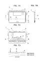
- FIGS. 7A to 7D depict an example of a deflection correcting rib
- FIGS. 8A to 8D depict an example of a deflection correcting rib
- FIGS. 9A to 9D depict an example of a touch pad cover
- FIGS. 10A to 10E depict an example of a deflection correcting rib.
- FIGS. 1A, 1B, and 1C depict an example of a notebook personal computer.
- a touch pad of a large size is disposed on a panel 3 adjacent to a keyboard section 2 .
- an independent right-click button 6 and an independent left-click button 7 are disposed in a lower part of a touch pad 4 on the panel 3 adjacent to the keyboard section 2 .
- the right-click button 6 and the left-click button 7 are present in the touch pad 4 of a larger size.
- the touch pad depicted in FIG. 1C has the structure different from that of the touch pad and the click button depicted in FIG. 1B .
- the supporting plate is secured to the housing at three points (left and right sides of the front end side and the middle of the rear end side) and a switch receptacle is disposed in a triangle formed by these three securing points.
- the entire touch pad is dented and the appearance may deteriorate.
- the reinforcing plate is inserted between the touch pad and the supporting plate so as to reduce an erroneous pressing of the touch pad by the deformation of the touch pad. This increases the number of components and makes the structure complicated, thereby possibly increasing the production cost.
- an undeflectable area and a deflectable area are provided in a large touch pad, and, only when pressing the deflectable area, the touch pad deflects and the switch element starts operating (clicking).
- FIG. 2A depicts an example of a touch pad.
- FIG. 2A is a perspective view depicting the assembly of a touch pad 4 , which is an input apparatus including a touch pad cover 20 .
- the touch pad 4 may be, for example, an input apparatus mounted on a keyboard section 2 of the notebook personal computer 1 , which is the electronic apparatus depicted in FIG. 1A .
- the touch pad 4 includes a touch pad unit 10 , which detects a touched position on the input surface, and the touch pad cover 20 , which is attached to the rear surface of the touch pad unit 10 .
- a glazed sheet 8 is attached to the upper surface of the touch pad unit 10 .
- the side of the touch pad 4 closed to the keyboard section 2 is called the upper end side and the side away from the keyboard section 2 is called the lower end side. Also in the touch pad unit 10 and the touch pad cover 20 , the side close to the keyboard section 2 is called the upper end side and the side away from the keyboard section 2 is called the lower end side.
- a click button 9 is mounted in the middle of the lower end part on the rear surface of the touch pad unit 10 .
- a connector 14 is disposed in the middle in the vicinity of the upper end part.
- a controller IC 13 is mounted in a section adjacent to the connector 14 .
- the touch pad cover 20 attached to the rear surface of the touch pad unit 10 has, therein, a window 23 through which the click button 9 mounted on the rear surface of the touch pad unit 10 passes and an opening 24 that keeps the touch pad cover 20 from making contact with the controller IC 13 and the connector 14 . Accordingly, in a state where the touch pad cover 20 is attached to the rear surface of the touch pad unit 10 , the click button 9 may be exposed through the window 23 and the controller IC 13 and the connector 14 may be exposed through the window 24 .
- a plurality of deflection correcting ribs 27 are disposed at certain intervals.
- the plurality of deflection correcting ribs 27 distribute more depression force when the input surface of the lower end side of the touch pad unit 10 is pressed to the sides of the touch pad cover 20 .
- a reinforcing rib 28 is disposed on the lower end side adjacent to the deflection correcting ribs 27 .
- FIG. 2B depicts a circuit of a touch pad.
- the controller IC 13 includes a touch sensor controller 13 A and a click button controller 13 B coupled to the touch sensor controller 13 A.
- the touch sensor controller 13 A is coupled to a touch sensor 15 , which detects an input to the touch pad unit 10
- the click button controller 13 B is coupled to the click button 9 .
- the touch sensor controller 13 A is coupled to the connector 14 .
- a touch input to the input surface is detected by the touch sensor 15 and the touch sensor controller 13 A.
- the touch pad unit 10 is of a capacitive type
- grid-like X electrodes (for example, 16) and Y electrodes (for example, 12) for detecting, for example, finger operation are disposed on the input surface of the touch pad unit 10 and electric energy is stored between the electrodes. If no operation is performed on the input surface, the two types of electrodes form a stable electric field.
- the electric field changes.
- the capacitance reduces at the position with which the fingers make contact.
- the touch sensor controller 13 A detects changes in the capacitance and the coordinates (touch position) at which the fingers made contact with the input surface.
- the click button controller 13 B determines whether a right click or a left click has been performed based on touch position detection results from the touch sensor controller 13 A. For example, when the lower end side of the touch pad unit 10 is pressed to press the click button 9 , the click button controller 13 B determines whether the right side or the left side of the touch pad unit 10 has been pressed, based on the results from the touch sensor controller 13 A. When the right side of the touch pad unit 10 has been pressed, the click button controller 13 B assumes a right click. When the left side of the touch pad unit 10 has been pressed, the click button controller 13 B assumes a left click. Information about the touch position and information indicating a right or left click are input to the controller of the personal computer via the connector 14 .
- FIG. 3A is a front plan view of a touch pad.
- FIG. 3A depicts the upper side after the touch pad 4 depicted in FIG. 2A is assembled.
- FIG. 3B is an example of a back plan view of a touch pad.
- FIG. 3B depicts the rear surface of touch pad 4 depicted in FIG. 3A .
- An undeflectable area 11 A and a deflectable area 11 B are disposed on the upper surface (touch input surface) 11 of the touch pad unit 10 that forms the touch pad 4 .
- the structure of the touch pad cover 20 attached to the rear surface of the touch pad unit 10 may determine whether the touch pad unit 10 is deflectable or undeflectable.
- a planar mount 25 which is formed integrally with the touch cover 20 and extends from the touch cover 20 to an external, is provided in the upper end part of the touch pad cover 20 and both sides with a certain length from the upper end part to the lower end part. For example, a step is disposed between the touch pad cover 20 and the mount 25 . Securing holes 25 A are disposed at certain intervals in the section of the mount 25 adjacent to the upper end part of the touch pad cover 20 . A screw hole 26 is disposed in each of both ends of the mount 25 . For example, the number of securing holes 25 A disposed in the mount 25 may be four.
- An opening 24 is disposed in the vicinity of the upper end part of the touch pad cover 20 .
- the controller IC 13 and the connector 14 disposed on the rear surface of the touch pad unit 10 are exposed in the opening 24 .
- the controller IC 13 and the connector 14 position on the rear surface of the undeflectable area 11 A of the touch pad unit 10 .
- the window 23 is disposed in the middle close to the lower end part of the touch pad cover 20 .
- the click button 9 disposed on the rear surface of the touch pad unit 10 is exposed in the window 23 when the touch pad unit 10 is attached to the upper surface of the touch pad cover 20 .
- the ribs 27 and the rib 28 which have mutually different functions, are disposed on an area provided lower than the lower end side of the opening 24 disposed in the touch pad cover 20 .
- the ribs 27 are the deflection correcting rib, which distributes more depression force to the sides of the touch pad cover 20 when the input surface at the lower end side of touch pad unit 10 is pressed.
- the plurality of ribs 27 may be disposed symmetrically about the center line CL of the touch pad cover 20 .
- the rib 28 may be a reinforcing rib that reinforces the lower end side of the touch pad cover 20 and is disposed on both sides of the window 23 on the rear surface of the touch pad cover 20 .
- the reinforcing rib 28 includes a linear rib 28 L disposed in a direction orthogonal to the center line CL on the upper end side of the window 23 .
- the linear rib 28 L functions as a border between the two types of ribs 27 and 28 .
- the number of ribs 27 may be four.
- the ribs 27 are disposed obliquely with respect to the center line CL so as to begin with the center line CL of the touch pad cover 20 and ends with the linear rib 28 L.
- the lowermost rib 27 is coupled to the linear rib 28 L as a straight line.
- the other ribs 27 are coupled to the linear rib 28 L via curved portions that are curved in the vicinity of the linear rib 28 L.
- the first and second ribs are coupled to a communication rib 27 L and the third and fourth ribs are coupled to another communication rib 27 L on the center line CL.
- the communication ribs 27 L may be disposed for each pair of ribs 27 or may be disposed in positions away from the center line CL in parallel with them, instead of on the center line CL.
- FIG. 4A is an example of a perspective view depicting an assembly of a notebook personal computer.
- a touch pad installation hole 31 is disposed in an upper housing 30 of the notebook personal computer, which is an input apparatus on which the touch pad 4 is mounted.
- Four latches 35 corresponding to the securing holes 25 A disposed in the touch pad cover 20 are disposed at an end (upper end side of the touch pad 4 ) of the inside of the installation hole 31 .
- Bosses 33 corresponding to screw holes 26 disposed in the touch pad cover 20 are disposed on both ends of the touch pad installation hole 31 that are closer to the latches 35 .
- a depressing projection 34 is disposed in a position corresponding to the click button 9 disposed on the touch pad cover 20 .
- FIG. 4B is a partial rear view depicting a touch pad.
- FIG. 4B depicts the state where the touch pad 4 is attached and secured to the installation hole 31 .
- the upper end side of the touch pad cover 20 is secured by causing the four latches 35 to be engaged in the four securing holes 25 A in the mount 25 , and both ends of the mount 25 are secured to the bosses 33 with the screws 29 .
- the undeflectable area 11 A of the touch pad unit 10 present on the rear surface of the area may not be deflected.
- FIG. 5A depicts an example of an upper housing of a notebook personal computer.
- FIG. 5A depicts the side (upper surface) opposite to the rear surface of the upper housing 30 of the notebook personal computer depicted in FIG. 4B .
- FIG. 5B is a sectional view depicting section B-B (center line CL) in FIG. 5A .
- FIG. 5C depicts an example of a state of click operation.
- FIG. 5C is a sectional view depicting the states of individual components when click operation is performed in the state depicted in FIG. 5B .
- a border BL between the undeflectable area 11 A and the deflectable area 11 B may be the same as the line BL depicted in FIG. 4B or the line connecting both ends of the mount 25 .
- the depressing projection 34 disposed on the upper housing 30 faces the click button 9 mounted on the rear surface of the touch pad unit 10 .
- FIG. 5C when the end side of the touch pad unit 10 is clicked (pressed) by a finger of the operator, the touch pad unit 10 is deformed with respect to a rotation axis RA that positions in the border BL, and the click button 9 is pressed by the depressing projection 34 .
- FIG. 6A depicts a front view of a touch pad.
- FIG. 6B depicts a back view of a touch pad.
- a section indicated by a dotted line P at the right of a touch input surface 11 of the touch pad unit 10 depicted in FIG. 6A may be pressed.
- the section on the rear surface corresponding to the dotted line P depicted in FIG. 6A is also indicated by a dotted line P.
- the plurality of ribs 27 formed on the touch pad cover 20 obliquely toward the linear rib 28 L distributes depression force. In the distribution of depression force, more depression force is shifted to in the direction in which the touch pad cover 20 is easy to deflect and less depression force is shifted to the direction in which the touch pad cover 20 is not easy to deflect.
- the deflection component is shifted to the right part of the touch pad cover 20 and the left part of the touch input surface 11 of the touch pad unit 10 is not deflected so much because the left part is not pressed.
- the deflection component is shifted to the left part of the touch pad cover 20 and the right part of the touch input surface 11 of the touch pad unit 10 is not deflected so much because the right part is not pressed.
- the deflection correcting ribs 27 concentrates the deflection direction on one direction (left or right) regardless of the clicked position on the touch input surface 11 of the touch pad unit 10 as described above, the appearance is not degraded when the input surface 11 is pressed and input error may be reduced.
- FIGS. 7A to 7D depict an example of deflection correcting ribs.
- FIGS. 7A to 7D depict the case where the deflection correcting ribs 27 are disposed appropriately on the rear surface of the touch pad cover 20 .
- FIGS. 8A to 8D depict an example of deflection correcting ribs.
- FIGS. 8A to 8D depict the case where the deflection correcting ribs 27 are disposed inappropriately on the rear surface of the touch pad cover 20 .
- FIGS. 7A to 7D depict an example of deflection correcting ribs.
- FIGS. 8A to 8D depict the case where the deflection correcting ribs 27 are disposed inappropriately on the rear surface of the touch pad cover 20 .
- FIGS. 9A to 9D depict an example of a touch pad cover.
- FIGS. 9A to 9D depict the case where no deflection correcting ribs 27 are disposed on the rear surface of the touch pad cover 20 .
- FIGS. 7A, 8A, and 9A depict clicked positions PA and PB on the touch input surface 11 of the touch pad unit 10 .
- FIGS. 7B, 8B and 9B depict the side of the touch pad 4 .
- FIGS. 7C, 8C and 9C depict the rear surface of the touch pad cover 20 .
- FIGS. 7D, 8D and 9D depict the deflection of the touch pad cover 20 .
- the touch pad cover 20 is bent toward the pressed section, regardless of the pressed position on the touch pad unit 10 . Accordingly, operation error during clicking may be reduced.
- the deflection correcting ribs 27 are disposed inappropriately or no deflection correcting ribs 27 are disposed on the rear surface of the touch pad cover 20 as depicted in FIGS. 8D and 9D , the touch pad cover 20 is bent toward the pressed section if the pressed position is far from the center line of the touch pad unit 10 . However, if the pressed position is close to the center line of the touch pad unit 10 , the touch pad cover 20 is not bent toward the pressed section appropriately and the click button may operate incorrectly.
- FIGS. 10A to 10E depict an example of a deflection correcting rib.
- FIGS. 10A and 10B depict the deflection correcting ribs 27 disposed on the touch pad cover 20 of the touch pad 4 .
- FIG. 10A depicts a rear view of the touch pad 4 having the touch pad cover 20 .
- the deflection correcting ribs 27 of the touch pad cover 20 begin with the center line of the touch pad cover 20 , extend orthogonally to the center line, bent in a direction parallel with the center line in midway, and reach the linear rib 28 L.
- a communication rib 27 L for communicating between the deflection correcting ribs 27 is disposed on the center line of the touch pad cover 20 .
- FIG. 10B depicts a rear view of the touch pad 4 having the touch pad cover 20 .
- the deflection correcting ribs 27 of the touch pad cover 20 begin with the center line of the touch pad cover 20 and extend obliquely. Then, the deflection correcting ribs 27 excluding the uppermost rib 27 reach the linear rib 28 L. The uppermost rib 27 ends with a side of the touch pad cover 20 .
- the communication rib 27 L for communicating between the deflection correcting ribs 27 is disposed on the center line of the touch pad cover 20 .
- FIG. 10C depicts a rear view of the touch pad 4 having the touch pad cover 20 .
- the deflection correcting ribs 27 of the touch pad cover 20 begin with the center line of the touch pad cover 20 , extend orthogonally to the center line, and bent toward the lower end side in midway. In FIGS. 7A to 7D , for example, all of the curved portions of the ribs 27 reach the linear rib 28 L. In FIG. 10C , however, the two uppermost ribs 27 may end with a side of the touch pad cover 20 .
- the communication rib 27 L for communicating between the deflection correcting ribs 27 is disposed on the center line of the touch pad cover 20 .
- FIG. 10D depicts a rear view of the touch pad 4 having the touch pad cover 20 .
- the deflection correcting ribs 27 of the touch pad cover 20 begin with the center line of the touch pad cover 20 and extend obliquely.
- the uppermost rib 27 ends with a side of the touch pad cover 20 in FIG. 10B , but all of the ribs 27 may end with the linear rib 28 L in FIG. 10D .
- the communication rib 27 L for communicating between the deflection correcting ribs 27 is disposed on the center line of the touch pad cover 20 .
- FIG. 10E depicts a rear view of the touch pad 4 having the touch pad cover 20 .
- the deflection correcting ribs 27 of the touch pad cover 20 begin with the center line of the touch pad cover 20 and extend obliquely. Then, all of the deflection correcting ribs 27 reach the linear rib 28 L as straight lines.
- the deflection correcting ribs 27 of the touch pad cover 20 begin with the center line of the touch pad cover 20 and extend obliquely, but all of the deflection correcting ribs 27 reach the linear rib 28 L as curved lines, not straight lines.
- the communication rib 27 L for communicating between the deflection correcting ribs 27 is disposed on the center line of the touch pad cover 20 .
- the shape of the deflection correcting rib 27 has only to be configured to concentrate the deflection of the touch pad cover 20 on the left or right side of the touch pad cover 20 , regardless of the pressed position on the touch pad unit 10 .
Landscapes
- Engineering & Computer Science (AREA)
- Computer Hardware Design (AREA)
- Theoretical Computer Science (AREA)
- Human Computer Interaction (AREA)
- Physics & Mathematics (AREA)
- General Engineering & Computer Science (AREA)
- General Physics & Mathematics (AREA)
- Position Input By Displaying (AREA)
- Tumbler Switches (AREA)
- User Interface Of Digital Computer (AREA)
Abstract
Description
Claims (20)
Applications Claiming Priority (2)
| Application Number | Priority Date | Filing Date | Title |
|---|---|---|---|
| JP2013-074186 | 2013-03-29 | ||
| JP2013074186A JP6032101B2 (en) | 2013-03-29 | 2013-03-29 | INPUT DEVICE AND ELECTRONIC DEVICE HAVING THE INPUT DEVICE |
Publications (2)
| Publication Number | Publication Date |
|---|---|
| US20140293157A1 US20140293157A1 (en) | 2014-10-02 |
| US9563237B2 true US9563237B2 (en) | 2017-02-07 |
Family
ID=51620508
Family Applications (1)
| Application Number | Title | Priority Date | Filing Date |
|---|---|---|---|
| US14/177,331 Expired - Fee Related US9563237B2 (en) | 2013-03-29 | 2014-02-11 | Input apparatus, electronic apparatus and touch pad |
Country Status (2)
| Country | Link |
|---|---|
| US (1) | US9563237B2 (en) |
| JP (1) | JP6032101B2 (en) |
Cited By (1)
| Publication number | Priority date | Publication date | Assignee | Title |
|---|---|---|---|---|
| US20240168526A1 (en) * | 2022-11-23 | 2024-05-23 | Acer Incorporated | Body structure of portable computer |
Families Citing this family (8)
| Publication number | Priority date | Publication date | Assignee | Title |
|---|---|---|---|---|
| US9984838B2 (en) * | 2014-08-29 | 2018-05-29 | Hewlett-Packard Development Company, L.P. | Click pad |
| US9652057B2 (en) * | 2014-12-31 | 2017-05-16 | Synaptics Incorporated | Top mount clickpad module for bi-level basin |
| JP6940040B2 (en) | 2016-02-04 | 2021-09-22 | ホアウェイ・テクノロジーズ・カンパニー・リミテッド | Information processing methods and electronic devices |
| US9891674B2 (en) * | 2016-03-04 | 2018-02-13 | Dell Products L.P. | Information handling system planar integrated button touch pad assembly |
| JP6581924B2 (en) * | 2016-03-07 | 2019-09-25 | アルプスアルパイン株式会社 | Touchpad input device |
| JP2020119099A (en) | 2019-01-21 | 2020-08-06 | レノボ・シンガポール・プライベート・リミテッド | Touch pad and electronic device |
| JP2020202164A (en) * | 2019-06-13 | 2020-12-17 | レノボ・シンガポール・プライベート・リミテッド | Input device and electronic apparatus |
| CN114690918A (en) * | 2022-03-16 | 2022-07-01 | 苏州三星电子电脑有限公司 | Touch pad unit and electronic device with same |
Citations (6)
| Publication number | Priority date | Publication date | Assignee | Title |
|---|---|---|---|---|
| JP2002046789A (en) | 2000-08-07 | 2002-02-12 | Hagoromo:Kk | Storage case |
| US20110149534A1 (en) * | 2009-12-18 | 2011-06-23 | Kabushiki Kaisha Toshiba | Electronic device |
| US20110149523A1 (en) * | 2009-12-22 | 2011-06-23 | Kabushiki Kaisha Toshiba | Electronic device |
| US20110249383A1 (en) * | 2010-04-12 | 2011-10-13 | Kabushiki Kaisha Toshiba | Electronic apparatus |
| US20120162892A1 (en) * | 2010-12-24 | 2012-06-28 | Kabushiki Kaisha Toshiba | Electronic apparatus |
| JP2013008123A (en) | 2011-06-23 | 2013-01-10 | Alps Electric Co Ltd | Input device having movable touch pad |
Family Cites Families (3)
| Publication number | Priority date | Publication date | Assignee | Title |
|---|---|---|---|---|
| JP3330666B2 (en) * | 1993-04-08 | 2002-09-30 | 株式会社ブリヂストン | Storage pad for airbag and method for manufacturing the storage pad |
| US8441450B2 (en) * | 2008-09-30 | 2013-05-14 | Apple Inc. | Movable track pad with added functionality |
| JP2009117377A (en) * | 2009-01-16 | 2009-05-28 | Toshiba Corp | Electronics |
-
2013
- 2013-03-29 JP JP2013074186A patent/JP6032101B2/en not_active Expired - Fee Related
-
2014
- 2014-02-11 US US14/177,331 patent/US9563237B2/en not_active Expired - Fee Related
Patent Citations (6)
| Publication number | Priority date | Publication date | Assignee | Title |
|---|---|---|---|---|
| JP2002046789A (en) | 2000-08-07 | 2002-02-12 | Hagoromo:Kk | Storage case |
| US20110149534A1 (en) * | 2009-12-18 | 2011-06-23 | Kabushiki Kaisha Toshiba | Electronic device |
| US20110149523A1 (en) * | 2009-12-22 | 2011-06-23 | Kabushiki Kaisha Toshiba | Electronic device |
| US20110249383A1 (en) * | 2010-04-12 | 2011-10-13 | Kabushiki Kaisha Toshiba | Electronic apparatus |
| US20120162892A1 (en) * | 2010-12-24 | 2012-06-28 | Kabushiki Kaisha Toshiba | Electronic apparatus |
| JP2013008123A (en) | 2011-06-23 | 2013-01-10 | Alps Electric Co Ltd | Input device having movable touch pad |
Cited By (2)
| Publication number | Priority date | Publication date | Assignee | Title |
|---|---|---|---|---|
| US20240168526A1 (en) * | 2022-11-23 | 2024-05-23 | Acer Incorporated | Body structure of portable computer |
| US12429928B2 (en) * | 2022-11-23 | 2025-09-30 | Acer Incorporated | Body structure of portable computer |
Also Published As
| Publication number | Publication date |
|---|---|
| JP2014199526A (en) | 2014-10-23 |
| JP6032101B2 (en) | 2016-11-24 |
| US20140293157A1 (en) | 2014-10-02 |
Similar Documents
| Publication | Publication Date | Title |
|---|---|---|
| US9563237B2 (en) | Input apparatus, electronic apparatus and touch pad | |
| CN106155189B (en) | electronic device | |
| CN205680068U (en) | Electrode slice | |
| CN105072220B (en) | Electronic equipment and key-press mounting structure | |
| US8890826B2 (en) | Position detection sensor unit and position detection apparatus | |
| US20100103611A1 (en) | Electronic device | |
| US20140176485A1 (en) | Touch screen, portable electronic device, and method of operating a touch screen | |
| US20150169005A1 (en) | Electronic device and touchpad assembly | |
| US20150160750A1 (en) | Electronic apparatus | |
| TWI590116B (en) | Touchpad module and electronic device | |
| US10861659B1 (en) | Touch input device | |
| US20170052611A1 (en) | Information processing apparatus and base member | |
| TW202016707A (en) | Touchpad device | |
| US20160143172A1 (en) | Electronic device | |
| CN110286806A (en) | A kind of touch pad input device and electronic equipment | |
| JP2015064852A (en) | Touch pad | |
| CN115668109A (en) | A support component, a touch panel and electronic equipment | |
| JP6581924B2 (en) | Touchpad input device | |
| JP6271671B1 (en) | INPUT DEVICE, ELECTRONIC DEVICE, AND METHOD FOR ASSEMBLING INPUT DEVICE | |
| JP3186414U (en) | Touchpad input device | |
| CN2809835Y (en) | button | |
| KR101448137B1 (en) | Touchscreen panel | |
| TWI321985B (en) | I/o shield and electronic apparatus using the same | |
| US9134769B2 (en) | Portable electronic device and an input module and a flexible bridging board thereof | |
| CN209590698U (en) | A kind of key and mobile terminal |
Legal Events
| Date | Code | Title | Description |
|---|---|---|---|
| AS | Assignment |
Owner name: FUJITSU LIMITED, JAPAN Free format text: ASSIGNMENT OF ASSIGNORS INTEREST;ASSIGNOR:HOSHI, MASAHIKO;REEL/FRAME:032193/0050 Effective date: 20140120 |
|
| STCF | Information on status: patent grant |
Free format text: PATENTED CASE |
|
| AS | Assignment |
Owner name: FUJITSU CLIENT COMPUTING LIMITED, JAPAN Free format text: ASSIGNMENT OF ASSIGNORS INTEREST;ASSIGNOR:FUJITSU LIMITED;REEL/FRAME:048751/0051 Effective date: 20181128 |
|
| MAFP | Maintenance fee payment |
Free format text: PAYMENT OF MAINTENANCE FEE, 4TH YEAR, LARGE ENTITY (ORIGINAL EVENT CODE: M1551); ENTITY STATUS OF PATENT OWNER: LARGE ENTITY Year of fee payment: 4 |
|
| FEPP | Fee payment procedure |
Free format text: MAINTENANCE FEE REMINDER MAILED (ORIGINAL EVENT CODE: REM.); ENTITY STATUS OF PATENT OWNER: LARGE ENTITY |
|
| LAPS | Lapse for failure to pay maintenance fees |
Free format text: PATENT EXPIRED FOR FAILURE TO PAY MAINTENANCE FEES (ORIGINAL EVENT CODE: EXP.); ENTITY STATUS OF PATENT OWNER: LARGE ENTITY |
|
| STCH | Information on status: patent discontinuation |
Free format text: PATENT EXPIRED DUE TO NONPAYMENT OF MAINTENANCE FEES UNDER 37 CFR 1.362 |
|
| FP | Lapsed due to failure to pay maintenance fee |
Effective date: 20250207 |