US9563045B2 - Surgical microscope apparatus and sealed drape - Google Patents
Surgical microscope apparatus and sealed drape Download PDFInfo
- Publication number
- US9563045B2 US9563045B2 US13/967,588 US201313967588A US9563045B2 US 9563045 B2 US9563045 B2 US 9563045B2 US 201313967588 A US201313967588 A US 201313967588A US 9563045 B2 US9563045 B2 US 9563045B2
- Authority
- US
- United States
- Prior art keywords
- surgical microscope
- arm
- drape
- lateral arm
- lateral
- Prior art date
- Legal status (The legal status is an assumption and is not a legal conclusion. Google has not performed a legal analysis and makes no representation as to the accuracy of the status listed.)
- Active
Links
Images
Classifications
-
- G—PHYSICS
- G02—OPTICS
- G02B—OPTICAL ELEMENTS, SYSTEMS OR APPARATUS
- G02B21/00—Microscopes
- G02B21/0004—Microscopes specially adapted for specific applications
- G02B21/0012—Surgical microscopes
-
- A—HUMAN NECESSITIES
- A61—MEDICAL OR VETERINARY SCIENCE; HYGIENE
- A61B—DIAGNOSIS; SURGERY; IDENTIFICATION
- A61B46/00—Surgical drapes
- A61B46/10—Surgical drapes specially adapted for instruments, e.g. microscopes
-
- A—HUMAN NECESSITIES
- A61—MEDICAL OR VETERINARY SCIENCE; HYGIENE
- A61B—DIAGNOSIS; SURGERY; IDENTIFICATION
- A61B90/00—Instruments, implements or accessories specially adapted for surgery or diagnosis and not covered by any of the groups A61B1/00 - A61B50/00, e.g. for luxation treatment or for protecting wound edges
- A61B90/20—Surgical microscopes characterised by non-optical aspects
-
- F—MECHANICAL ENGINEERING; LIGHTING; HEATING; WEAPONS; BLASTING
- F04—POSITIVE - DISPLACEMENT MACHINES FOR LIQUIDS; PUMPS FOR LIQUIDS OR ELASTIC FLUIDS
- F04C—ROTARY-PISTON, OR OSCILLATING-PISTON, POSITIVE-DISPLACEMENT MACHINES FOR LIQUIDS; ROTARY-PISTON, OR OSCILLATING-PISTON, POSITIVE-DISPLACEMENT PUMPS
- F04C2270/00—Control; Monitoring or safety arrangements
- F04C2270/04—Force
- F04C2270/042—Force radial
- F04C2270/0421—Controlled or regulated
Definitions
- the present invention relates to a surgical microscope apparatus used with a drape that covers the apparatus.
- the surgical microscope apparatus suspends a surgical microscope in midair and is used for, for example, neurosurgery.
- the apparatus includes a stand that is set on a floor, a longitudinal arm that is uprightly and pivotally supported with the stand, and a lateral arm that has a base end pivotally supported at an upper end of the longitudinal arm and horizontally extends from the upper end of the longitudinal arm, the surgical microscope being suspended from a front end of the lateral arm.
- the surgical microscope and part of the horizontal and longitudinal arms are covered with a drape to secure an aseptic condition.
- Patent Literature 1 discloses a technique of drawing air from the inside of the drape so that the drape may tightly be attached to the surgical microscope apparatus.
- the present invention provides a surgical microscope apparatus capable of drawing air only from around a surgical microscope covered with a drape.
- the surgical microscope apparatus has a stand body, a longitudinal arm pivotally supported with the stand body, a lateral arm whose base end is pivotally supported at an upper end of the longitudinal arm, a surgical microscope supported in the vicinity of a front end of the lateral arm, and a drape distributing over a predetermined area of the apparatus ranging from the surgical microscope to the longitudinal arm.
- the apparatus includes a hollow structure provided for each of the vertical and lateral arms, an intake port formed in the vicinity of the front end of the lateral arm, a discharge port provided for one of the horizontal and longitudinal arms, pivotal parts arranged in an area of the apparatus ranging from the intake port to the discharge port, each pivotal part having a ventilating structure to form a ventilating path between the intake port and the discharge port, and a discharge unit arranged in the ventilating path.
- FIG. 1 is a side view illustrating a surgical microscope apparatus according to an embodiment of the present invention
- FIG. 2 is a side view corresponding to FIG. 1 , illustrating the surgical microscope apparatus with a drape in a drawn state;
- FIG. 3 is aperspectiveview illustrating a surgical microscope of the surgical microscope apparatus and the periphery of the surgical microscope;
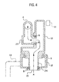
- FIG. 4 is a sectional view illustrating a front end area of a lateral arm of the surgical microscope apparatus.
- FIG. 5 is a sectional view illustrating a base end area of the lateral arm.
- FIGS. 1 to 5 A surgical microscope apparatus according to an embodiment of the present invention will be explained with reference to FIGS. 1 to 5 .
- a stand body 1 of the surgical microscope apparatus is installed on a base 2 that is set on a floor.
- An upper part of the stand body 1 has a pivotal part J 1 that pivotally supports a longitudinal arm (a first arm) 3 .
- the longitudinal arm 3 has a hollow structure and uprightly extends.
- a lower end of the longitudinal arm 3 is connected to a bar 4 , which is connected to a counterweight 5 .
- An upper end of the longitudinal arm 3 is connected to a lateral arm (a second arm) 6 that has a hollow structure and extends horizontally.
- the lateral arm 6 has a thick base end 7 .
- the base end 7 has a pivotal part J 2 that is connected to the upper end of the longitudinal arm 3 .
- An end of the base end 7 is connected through a longitudinal sub-arm 8 to the bar 4 .
- the longitudinal sub-arm 8 is substantially parallel to the longitudinal arm 3 .
- Four pivotal parts that support the longitudinal arm 3 and longitudinal sub-arm 8 form a parallel linkage.
- the base end 7 of the lateral arm 6 has a vertical link 9 .
- the vertical link 9 With an inner structure (not illustrated) and a lateral sub-arm 11 , the vertical link 9 always maintains a vertical (perpendicular) state even if the longitudinal arm 3 or the lateral arm 6 inclines.
- the lateral arm 6 is upwardly curved between the base and front ends thereof.
- the front end of the lateral arm 6 is connected through a pivotal part J 3 to a front member 10 that is L-shaped in cross section and has a hollow structure.
- An upper end of the front member 10 is connected through the lateral sub-arm 11 to an upper end of the vertical link 9 .
- the lateral sub-arm 11 is substantially parallel to the lateral arm 6 .
- the lateral arm 6 and lateral sub-arm 11 are supported with four pivotal parts to form a parallel linkage.
- the front member 10 is connected through the lateral sub-arm 11 to the vertical link 9 , and therefore, the front member 10 always keeps a vertical position.
- a lower part of the front member 10 is connected through a pivotal part J 4 to a rotary body 12 .
- the rotary body 12 has a box shape and is rotatable around the pivotal part J 4 .
- the rotary body 12 is connected to a support arm 13 that supports a surgical microscope 14 . With the surgical microscope 14 , a surgeon D observes an enlarged image of an objective part of a patient and carries out a surgery.
- the longitudinal arm 3 , lateral arm 6 , front member 10 , and rotary body 12 each have a hollow structure, to form an inner space of FIG. 4 that is continuous through the pivotal part J 3 between the lateral arm 6 and the front member 10 and the pivotal part J 4 between the front member 10 and the rotary body 12 .
- This continuous inner space realizes ventilation.
- the lateral arm 6 and front member 10 are connected to each other so that they are rotatable relative to each other through bearings B and communicate with each other.
- the front member 10 and rotary body 12 are connected to each other so that they are rotatable relative to each other through bearings B.
- a lower end of the rotary body 12 is opened to form an intake port 15 .
- the intake port 15 communicates with an inner space of the front member 10 , to form part of a ventilating path A that extends from the intake port 15 to the longitudinal arm 3 .
- the base end 7 of the lateral arm 6 includes a discharge port 16 and a discharge fan 17 to serve the discharge unit stipulated in the claims.
- a closed space having two openings ( 15 , 16 ) is defined through the lateral arm 6 up to the intake port 15 .
- the discharge unit generates a pressure gradient to discharge air from the intake port 15 to the discharge port 16 and is arrangeable at any location in the ventilating path A.
- the drape P is put around the surgical microscope 14 , lateral arm 6 , and longitudinal arm 3 .
- An eyepiece 14 a of the surgical microscope 14 is set to protrude out of the drape P.
- An objective lens of the surgical microscope 14 is provided with a cap (not illustrated).
- the drape P distributing around the lateral arm 6 and longitudinal arm 3 is partly fastened with bands 18 and 19 so that the drape P may not sag.
- the drape P distributing around the rotary body 12 is tightly fastened with a band 20 .
- the discharge fan 17 is driven to draw air from around the surgical microscope 14 through the intake port 15 of the rotary body 12 .
- the drape P distributing around the surgical microscope 14 tightly attaches to the surgical microscope 14 , to never block the field of vision of the surgeon D.
- the drape P distributing around the lateral arm 6 and longitudinal arm 3 is not attracted and is only partly bound with the bands 18 and 19 . Accordingly, movements of the lateral arm 6 and longitudinal arm 3 are not restricted by the drape P.
- the hollow structures of the lateral arm 6 and front member 10 form the continuous inner space that is used as the ventilating path. This eliminates the need of separate suction tubes or the like for drawing air from around the surgical microscope 14 .
- the rotary body 12 is always maintained at a vertical position, and therefore, the surgical microscope 14 is supported always in a perpendicular state irrespective of movements of the lateral arm 6 and the like. This improves the handling of the surgical microscope 14 .
- the surgical microscope 14 Since the surgical microscope 14 is vertically supported, the motion of the surgical microscope 14 is minimized to rotation around a vertical axis. Accordingly, no problem occurs even when the drape P is tightly attached to the surgical microscope 14 .
- the discharge unit is arranged in the base end 7 of the lateral arm 6 .
- the pivotal part J 2 between the lateral arm 6 and the longitudinal arm 3 may have a ventilating structure and the discharge unit may be arranged inside the longitudinal arm 3 .
- the intake port is formed on the front end side of the lateral arm.
- the drape put around the surgical microscope apparatus is drawn only around the surgical microscope. Drawing the drape around the surgical microscope clears the visibility of a surgeon who handles the surgical microscope.
- the drape distributing around the horizontal and longitudinal arms is not drawn, and therefore, the operability of the surgical microscope apparatus is secured.
- the lateral arm and the like are hollow to form the inner ventilating path, and therefore, there is no need of separately preparing suction tubes or the like for drawing air from the inside of the drape around the surgical microscope.
- the rotary body is kept vertical to secure the vertical state of the surgical microscope even when the lateral arm and the like are widely moved. Due to this, the surgical microscope is easy to handle. Since the surgical microscope is always vertical, the motion of the surgical microscope is minimized to cause no problem when the drape around the surgical microscope is tightly attracted.
Landscapes
- Health & Medical Sciences (AREA)
- Surgery (AREA)
- Life Sciences & Earth Sciences (AREA)
- General Health & Medical Sciences (AREA)
- Public Health (AREA)
- Molecular Biology (AREA)
- Veterinary Medicine (AREA)
- Animal Behavior & Ethology (AREA)
- Medical Informatics (AREA)
- Engineering & Computer Science (AREA)
- Biomedical Technology (AREA)
- Heart & Thoracic Surgery (AREA)
- Physics & Mathematics (AREA)
- Nuclear Medicine, Radiotherapy & Molecular Imaging (AREA)
- Oral & Maxillofacial Surgery (AREA)
- Pathology (AREA)
- Analytical Chemistry (AREA)
- Optics & Photonics (AREA)
- Chemical & Material Sciences (AREA)
- General Physics & Mathematics (AREA)
- Microscoopes, Condenser (AREA)
Abstract
At a front end of the lateral arm of a surgical microscope apparatus, the apparatus has an intake port. A band is tied around the front end of the lateral arm so that a drape is drawn only to a surgical microscope. Drawing the drape to the surgical microscope results in clearing the field of vision of a surgeon. Part of the drape around the lateral arm and a longitudinal arm is not drawn, to cause no hindrance in operability of the surgical microscope. The lateral arm and the like are hollow to form an inner ventilating path without separately preparing ventilating tubes or the like for ventilation.
Description
1. Field of the Invention
The present invention relates to a surgical microscope apparatus used with a drape that covers the apparatus.
2. Description of Related Art
The surgical microscope apparatus suspends a surgical microscope in midair and is used for, for example, neurosurgery. The apparatus includes a stand that is set on a floor, a longitudinal arm that is uprightly and pivotally supported with the stand, and a lateral arm that has a base end pivotally supported at an upper end of the longitudinal arm and horizontally extends from the upper end of the longitudinal arm, the surgical microscope being suspended from a front end of the lateral arm.
The surgical microscope and part of the horizontal and longitudinal arms are covered with a drape to secure an aseptic condition.
If the drape loosens and sags, it will obstruct the visibility of a surgeon. To deal with this problem, Japanese Patent Publication No. 2988980 (Patent Literature 1) discloses a technique of drawing air from the inside of the drape so that the drape may tightly be attached to the surgical microscope apparatus.
This related art, however, pulls the drape not only from around the surgical microscope but also from around the lateral atm to tightly attach the drape to the lateral arm. The tightly attached drape prevents a free movement of the lateral arm, thereby deteriorating the operability of the surgical microscope apparatus.
The present invention provides a surgical microscope apparatus capable of drawing air only from around a surgical microscope covered with a drape.
According to an aspect of the present invention, the surgical microscope apparatus has a stand body, a longitudinal arm pivotally supported with the stand body, a lateral arm whose base end is pivotally supported at an upper end of the longitudinal arm, a surgical microscope supported in the vicinity of a front end of the lateral arm, and a drape distributing over a predetermined area of the apparatus ranging from the surgical microscope to the longitudinal arm. According to this aspect of the present invention, the apparatus includes a hollow structure provided for each of the vertical and lateral arms, an intake port formed in the vicinity of the front end of the lateral arm, a discharge port provided for one of the horizontal and longitudinal arms, pivotal parts arranged in an area of the apparatus ranging from the intake port to the discharge port, each pivotal part having a ventilating structure to form a ventilating path between the intake port and the discharge port, and a discharge unit arranged in the ventilating path.
A surgical microscope apparatus according to an embodiment of the present invention will be explained with reference to FIGS. 1 to 5 .
A stand body 1 of the surgical microscope apparatus is installed on a base 2 that is set on a floor. An upper part of the stand body 1 has a pivotal part J1 that pivotally supports a longitudinal arm (a first arm) 3. The longitudinal arm 3 has a hollow structure and uprightly extends. A lower end of the longitudinal arm 3 is connected to a bar 4, which is connected to a counterweight 5.
An upper end of the longitudinal arm 3 is connected to a lateral arm (a second arm) 6 that has a hollow structure and extends horizontally. The lateral arm 6 has a thick base end 7. The base end 7 has a pivotal part J2 that is connected to the upper end of the longitudinal arm 3. An end of the base end 7 is connected through a longitudinal sub-arm 8 to the bar 4. The longitudinal sub-arm 8 is substantially parallel to the longitudinal arm 3. Four pivotal parts that support the longitudinal arm 3 and longitudinal sub-arm 8 form a parallel linkage.
The base end 7 of the lateral arm 6 has a vertical link 9. With an inner structure (not illustrated) and a lateral sub-arm 11, the vertical link 9 always maintains a vertical (perpendicular) state even if the longitudinal arm 3 or the lateral arm 6 inclines.
The lateral arm 6 is upwardly curved between the base and front ends thereof. The front end of the lateral arm 6 is connected through a pivotal part J3 to a front member 10 that is L-shaped in cross section and has a hollow structure. An upper end of the front member 10 is connected through the lateral sub-arm 11 to an upper end of the vertical link 9. The lateral sub-arm 11 is substantially parallel to the lateral arm 6. The lateral arm 6 and lateral sub-arm 11 are supported with four pivotal parts to form a parallel linkage.
The front member 10 is connected through the lateral sub-arm 11 to the vertical link 9, and therefore, the front member 10 always keeps a vertical position. A lower part of the front member 10 is connected through a pivotal part J4 to a rotary body 12. The rotary body 12 has a box shape and is rotatable around the pivotal part J4. The rotary body 12 is connected to a support arm 13 that supports a surgical microscope 14. With the surgical microscope 14, a surgeon D observes an enlarged image of an objective part of a patient and carries out a surgery.
The longitudinal arm 3, lateral arm 6, front member 10, and rotary body 12 each have a hollow structure, to form an inner space of FIG. 4 that is continuous through the pivotal part J3 between the lateral arm 6 and the front member 10 and the pivotal part J4 between the front member 10 and the rotary body 12. This continuous inner space realizes ventilation.
At the pivotal part J3, the lateral arm 6 and front member 10 are connected to each other so that they are rotatable relative to each other through bearings B and communicate with each other.
At the pivotal part J4, the front member 10 and rotary body 12 are connected to each other so that they are rotatable relative to each other through bearings B. A lower end of the rotary body 12 is opened to form an intake port 15. The intake port 15 communicates with an inner space of the front member 10, to form part of a ventilating path A that extends from the intake port 15 to the longitudinal arm 3.
As illustrated in FIG. 5 , the base end 7 of the lateral arm 6 includes a discharge port 16 and a discharge fan 17 to serve the discharge unit stipulated in the claims. With this, a closed space (ventilating path A) having two openings (15, 16) is defined through the lateral arm 6 up to the intake port 15. When the discharge fan 17 is driven to discharge air from the inside of the lateral arm 6 to the outside, circumferential air around the rotary body 12 is drawn through the intake port 15, front member 10, and lateral arm 6. The discharge unit generates a pressure gradient to discharge air from the intake port 15 to the discharge port 16 and is arrangeable at any location in the ventilating path A.
Operation of the surgical microscope apparatus covered with a drape P will be explained.
The drape P is put around the surgical microscope 14, lateral arm 6, and longitudinal arm 3. An eyepiece 14 a of the surgical microscope 14 is set to protrude out of the drape P. An objective lens of the surgical microscope 14 is provided with a cap (not illustrated).
The drape P distributing around the lateral arm 6 and longitudinal arm 3 is partly fastened with bands 18 and 19 so that the drape P may not sag. The drape P distributing around the rotary body 12 is tightly fastened with a band 20.
In this state, the discharge fan 17 is driven to draw air from around the surgical microscope 14 through the intake port 15 of the rotary body 12. This produces a pressure decrease to firmly attract the drape P only around the surgical microscope 14. Namely, the drape P distributing around the surgical microscope 14 tightly attaches to the surgical microscope 14, to never block the field of vision of the surgeon D. The drape P distributing around the lateral arm 6 and longitudinal arm 3 is not attracted and is only partly bound with the bands 18 and 19. Accordingly, movements of the lateral arm 6 and longitudinal arm 3 are not restricted by the drape P.
The hollow structures of the lateral arm 6 and front member 10 form the continuous inner space that is used as the ventilating path. This eliminates the need of separate suction tubes or the like for drawing air from around the surgical microscope 14.
According to the present embodiment, the rotary body 12 is always maintained at a vertical position, and therefore, the surgical microscope 14 is supported always in a perpendicular state irrespective of movements of the lateral arm 6 and the like. This improves the handling of the surgical microscope 14.
Since the surgical microscope 14 is vertically supported, the motion of the surgical microscope 14 is minimized to rotation around a vertical axis. Accordingly, no problem occurs even when the drape P is tightly attached to the surgical microscope 14.
According to the present embodiment, the discharge unit is arranged in the base end 7 of the lateral arm 6. Instead, the pivotal part J2 between the lateral arm 6 and the longitudinal arm 3 may have a ventilating structure and the discharge unit may be arranged inside the longitudinal arm 3.
According to the present invention, the intake port is formed on the front end side of the lateral arm. By binding a front end part of the lateral arm with a band or the like, the drape put around the surgical microscope apparatus is drawn only around the surgical microscope. Drawing the drape around the surgical microscope clears the visibility of a surgeon who handles the surgical microscope. The drape distributing around the horizontal and longitudinal arms is not drawn, and therefore, the operability of the surgical microscope apparatus is secured. The lateral arm and the like are hollow to form the inner ventilating path, and therefore, there is no need of separately preparing suction tubes or the like for drawing air from the inside of the drape around the surgical microscope.
According to the present invention, the rotary body is kept vertical to secure the vertical state of the surgical microscope even when the lateral arm and the like are widely moved. Due to this, the surgical microscope is easy to handle. Since the surgical microscope is always vertical, the motion of the surgical microscope is minimized to cause no problem when the drape around the surgical microscope is tightly attracted.
This application claims benefit of priority under 35 USC §119 to Japanese Patent Application No. 2012-183003, filed on Aug. 22, 2012, the entire contents of which are incorporated by reference herein. Although the invention has been described above by reference to certain embodiments of the invention, the invention is not limited to the embodiments described above. Modifications and variations of the embodiments described above will occur to those skilled in the art, in light of the teachings. The scope of the invention is defined with reference to the following claims.
Claims (2)
1. A surgical microscope apparatus having a stand body, a longitudinal arm pivotally supported with the stand body, a lateral arm pivotally supported at a base end thereof by an upper end of the longitudinal arm, a surgical microscope supported at a front end of the lateral arm, and a drape covering a predetermined area of the apparatus ranging from the surgical microscope to the longitudinal arm, comprising:
a hollow structure provided for each of the longitudinal and lateral arms;
an intake port formed at the front end of the lateral arm;
a discharge port provided at one of the lateral and longitudinal arms;
pivotal parts arranged in an area of the apparatus ranging from the intake port to the discharge port, each pivotal part having a ventilating structure to form a ventilating path between the intake port and the discharge port;
a discharge unit arranged in the ventilating path; and
a band tightly sealing the drape around the front end of the lateral arm at the surgical microscope, wherein the drape is tightly held only around the microscope; and
a front member having a hollow structure, the front member pivotally supported at the front end of the lateral arm; and
a vertical link connected to the base end of the lateral arm, the front member connected to the vertical link and maintained to be always vertical.
2. The surgical microscope apparatus of claim 1 , further comprising:
a rotary body pivotally supported at a lower end of the front member and rotatable around a vertical axis;
the intake port formed at a lower part of the rotary body; and
a pivotal part provided between the front member and the lateral arm and a pivotal part provided between the front member and the rotary body each being configured to pass air along the ventilating path therethrough.
Applications Claiming Priority (3)
Application Number | Priority Date | Filing Date | Title |
---|---|---|---|
JP2012183003A JP5879232B2 (en) | 2012-08-22 | 2012-08-22 | Surgical microscope equipment |
JPJP2012-183003 | 2012-08-22 | ||
JP2012-183003 | 2012-08-22 |
Publications (2)
Publication Number | Publication Date |
---|---|
US20140055850A1 US20140055850A1 (en) | 2014-02-27 |
US9563045B2 true US9563045B2 (en) | 2017-02-07 |
Family
ID=49035370
Family Applications (1)
Application Number | Title | Priority Date | Filing Date |
---|---|---|---|
US13/967,588 Active US9563045B2 (en) | 2012-08-22 | 2013-08-15 | Surgical microscope apparatus and sealed drape |
Country Status (3)
Country | Link |
---|---|
US (1) | US9563045B2 (en) |
EP (1) | EP2700374B1 (en) |
JP (1) | JP5879232B2 (en) |
Cited By (5)
Publication number | Priority date | Publication date | Assignee | Title |
---|---|---|---|---|
US20160281911A1 (en) * | 2015-03-24 | 2016-09-29 | Mitaka Kohki Co., Ltd. | Medical stand apparatus |
US20180008496A1 (en) * | 2013-03-14 | 2018-01-11 | Liko Research & Development Ab | Split drum for lift strap in ceiling lift |
USD875151S1 (en) | 2017-04-28 | 2020-02-11 | Ecolab Usa Inc. | Microscope drape |
USD877226S1 (en) | 2017-04-28 | 2020-03-03 | Ecolab Usa Inc. | Optical lens housing |
US11553972B2 (en) * | 2019-03-22 | 2023-01-17 | Sony Olympus Medical Solutions Inc. | Medical holding apparatus and medical observation system |
Families Citing this family (12)
Publication number | Priority date | Publication date | Assignee | Title |
---|---|---|---|---|
USD758465S1 (en) * | 2013-09-27 | 2016-06-07 | Carl Zeiss Meditec Ag | Surgical microscope |
JP6305187B2 (en) | 2014-04-21 | 2018-04-04 | 三鷹光器株式会社 | Surgical microscope system |
GB2584378B (en) * | 2014-11-20 | 2021-04-21 | Cmr Surgical Ltd | Cooling a surgical robotic arm |
JP6434359B2 (en) * | 2015-04-23 | 2018-12-05 | 三鷹光器株式会社 | Surgical microscope equipment |
US10122991B2 (en) | 2015-08-11 | 2018-11-06 | Mitaka Kohki Co., Ltd. | Surgical stereoscopic observation apparatus |
US9939603B2 (en) * | 2015-09-22 | 2018-04-10 | Novartis Ag | Brake system |
JP6769600B2 (en) * | 2016-07-14 | 2020-10-14 | 三鷹光器株式会社 | Surgical microscope device |
JP1589602S (en) * | 2017-03-30 | 2020-10-26 | ||
JP2020520694A (en) * | 2017-05-25 | 2020-07-16 | コヴィディエン リミテッド パートナーシップ | Drapes for covering robotic surgery systems and components of robotic surgery systems |
DE102018211395B4 (en) * | 2018-07-10 | 2021-05-27 | Carl Zeiss Meditec Ag | Surgical microscope stand with a sealing arrangement |
CN109745124B (en) * | 2019-01-25 | 2021-02-19 | 佳木斯大学附属第一医院 | Neurosurgery operation microscope device |
JP7352586B2 (en) | 2021-01-22 | 2023-09-28 | 日立グローバルライフソリューションズ株式会社 | storage room |
Citations (8)
Publication number | Priority date | Publication date | Assignee | Title |
---|---|---|---|---|
US5122904A (en) | 1989-10-23 | 1992-06-16 | Olympus Optical Co., Ltd. | Operating microscope with drape and suction means for removing air from the drape |
JPH06269461A (en) | 1993-03-18 | 1994-09-27 | Mitaka Koki Co Ltd | Heat dissipating structure of stand device |
US5970980A (en) | 1996-07-12 | 1999-10-26 | Adair; Edwin L. | Sterile encapsulated operating room video monitor and video monitor support device |
JP2988980B2 (en) | 1989-10-23 | 1999-12-13 | オリンパス光学工業株式会社 | Operation microscope |
US20030066534A1 (en) | 2001-09-20 | 2003-04-10 | Spetzler Robert F. | Medical instrument arrangement with drape |
US20040138650A1 (en) | 2002-11-12 | 2004-07-15 | Katsushige Nakamura | Rotary support structure for medical equipment |
US20050161176A1 (en) | 2004-01-27 | 2005-07-28 | Carl Zeiss Ag | Device holding apparatus |
JP2010046117A (en) | 2008-08-19 | 2010-03-04 | Mitaka Koki Co Ltd | Surgical microscopic system |
Family Cites Families (1)
Publication number | Priority date | Publication date | Assignee | Title |
---|---|---|---|---|
JP2988981B2 (en) | 1990-08-08 | 1999-12-13 | オリンパス光学工業株式会社 | Surgical microscope drape |
-
2012
- 2012-08-22 JP JP2012183003A patent/JP5879232B2/en active Active
-
2013
- 2013-08-15 US US13/967,588 patent/US9563045B2/en active Active
- 2013-08-22 EP EP13181342.0A patent/EP2700374B1/en not_active Not-in-force
Patent Citations (10)
Publication number | Priority date | Publication date | Assignee | Title |
---|---|---|---|---|
US5122904A (en) | 1989-10-23 | 1992-06-16 | Olympus Optical Co., Ltd. | Operating microscope with drape and suction means for removing air from the drape |
JP2988980B2 (en) | 1989-10-23 | 1999-12-13 | オリンパス光学工業株式会社 | Operation microscope |
JPH06269461A (en) | 1993-03-18 | 1994-09-27 | Mitaka Koki Co Ltd | Heat dissipating structure of stand device |
US5970980A (en) | 1996-07-12 | 1999-10-26 | Adair; Edwin L. | Sterile encapsulated operating room video monitor and video monitor support device |
US20030066534A1 (en) | 2001-09-20 | 2003-04-10 | Spetzler Robert F. | Medical instrument arrangement with drape |
JP2003220077A (en) | 2001-09-20 | 2003-08-05 | Carl Zeiss:Fa | Instrument having drape |
US20040138650A1 (en) | 2002-11-12 | 2004-07-15 | Katsushige Nakamura | Rotary support structure for medical equipment |
US20050161176A1 (en) | 2004-01-27 | 2005-07-28 | Carl Zeiss Ag | Device holding apparatus |
US7846086B2 (en) | 2004-01-27 | 2010-12-07 | Carlzeiss Ag | Device holding apparatus |
JP2010046117A (en) | 2008-08-19 | 2010-03-04 | Mitaka Koki Co Ltd | Surgical microscopic system |
Non-Patent Citations (3)
Title |
---|
EPO Search report, Dec. 2, 2013. |
Japan Office action, mail date is Feb. 18, 2014. |
Japan Office action, mail date is May 20, 2014. |
Cited By (9)
Publication number | Priority date | Publication date | Assignee | Title |
---|---|---|---|---|
US20180008496A1 (en) * | 2013-03-14 | 2018-01-11 | Liko Research & Development Ab | Split drum for lift strap in ceiling lift |
US10646392B2 (en) * | 2013-03-14 | 2020-05-12 | Liko Research & Development Ab | Split drum for lift strap in ceiling lift |
US11679049B2 (en) | 2013-03-14 | 2023-06-20 | Liko Research & Development Ab | Split drum for lift strap in ceiling strap |
US20160281911A1 (en) * | 2015-03-24 | 2016-09-29 | Mitaka Kohki Co., Ltd. | Medical stand apparatus |
US9822922B2 (en) * | 2015-03-24 | 2017-11-21 | Mitaka Kohki Co., Ltd. | Medical stand apparatus |
USD875151S1 (en) | 2017-04-28 | 2020-02-11 | Ecolab Usa Inc. | Microscope drape |
USD877226S1 (en) | 2017-04-28 | 2020-03-03 | Ecolab Usa Inc. | Optical lens housing |
USD1033502S1 (en) | 2017-04-28 | 2024-07-02 | Ecolab Usa Inc. | Optical lens housing |
US11553972B2 (en) * | 2019-03-22 | 2023-01-17 | Sony Olympus Medical Solutions Inc. | Medical holding apparatus and medical observation system |
Also Published As
Publication number | Publication date |
---|---|
JP5879232B2 (en) | 2016-03-08 |
EP2700374A1 (en) | 2014-02-26 |
EP2700374B1 (en) | 2018-04-18 |
US20140055850A1 (en) | 2014-02-27 |
JP2014039644A (en) | 2014-03-06 |
Similar Documents
Publication | Publication Date | Title |
---|---|---|
US9563045B2 (en) | Surgical microscope apparatus and sealed drape | |
JP6552592B2 (en) | Operating microscope apparatus and operating microscope system | |
EP1295568A1 (en) | Instrument having a drape | |
ES2882792T3 (en) | Display device of a digital image | |
US9746659B2 (en) | Surgical microscope system | |
EP2745038B1 (en) | Floor stand with angled arm for microscope | |
US9107618B2 (en) | Imaging accessory frame for integration with an operating microscope | |
WO2016047066A1 (en) | Medical robot cover | |
ES2542422T3 (en) | Surgical Microscope Cloth Set | |
JP5985601B2 (en) | Arm of arm structure for intraoral X-ray apparatus | |
US20140240832A1 (en) | Microdrape | |
US9822922B2 (en) | Medical stand apparatus | |
JP2968513B1 (en) | Stand device with monitor | |
JP6434359B2 (en) | Surgical microscope equipment | |
US6869194B2 (en) | Sterilizable drape for ophthalmoscopic lens | |
JP2018051117A (en) | Medical stand device | |
JP6097623B2 (en) | Auxiliary arm mounting structure of stand device | |
JP6769600B2 (en) | Surgical microscope device | |
JP5363891B2 (en) | Work hood and work box equipped with the work hood | |
IT202000011290A1 (en) | ASPIRATION SYSTEM FOR OPTICAL INSTRUMENTS | |
JP2014200275A (en) | Structure for fitting auxiliary arm of stand device | |
JP2021164527A (en) | Surgical microscope apparatus | |
JP2019048025A (en) | Stand device for surgical microscope | |
JP2017055728A (en) | Cell culture room and culture facility | |
JPH07143995A (en) | Stand device for optical instrument for medical treatment |
Legal Events
Date | Code | Title | Description |
---|---|---|---|
AS | Assignment |
Owner name: MITAKA KOHKI CO., LTD., JAPAN Free format text: ASSIGNMENT OF ASSIGNORS INTEREST;ASSIGNORS:DOI, MASAO;NAKATA, YUSUKE;REEL/FRAME:031017/0837 Effective date: 20130723 |
|
STCF | Information on status: patent grant |
Free format text: PATENTED CASE |
|
CC | Certificate of correction | ||
MAFP | Maintenance fee payment |
Free format text: PAYMENT OF MAINTENANCE FEE, 4TH YR, SMALL ENTITY (ORIGINAL EVENT CODE: M2551); ENTITY STATUS OF PATENT OWNER: SMALL ENTITY Year of fee payment: 4 |