US956209A - Profiling-machine. - Google Patents
Profiling-machine. Download PDFInfo
- Publication number
- US956209A US956209A US39516007A US1907395160A US956209A US 956209 A US956209 A US 956209A US 39516007 A US39516007 A US 39516007A US 1907395160 A US1907395160 A US 1907395160A US 956209 A US956209 A US 956209A
- Authority
- US
- United States
- Prior art keywords
- carriage
- standard
- cutter
- shaft
- profiler
- Prior art date
- Legal status (The legal status is an assumption and is not a legal conclusion. Google has not performed a legal analysis and makes no representation as to the accuracy of the status listed.)
- Expired - Lifetime
Links
- 230000007246 mechanism Effects 0.000 description 9
- 239000007788 liquid Substances 0.000 description 4
- 230000000284 resting effect Effects 0.000 description 3
- 230000001050 lubricating effect Effects 0.000 description 2
- 230000004048 modification Effects 0.000 description 2
- 238000012986 modification Methods 0.000 description 2
- 230000000717 retained effect Effects 0.000 description 2
- 230000013707 sensory perception of sound Effects 0.000 description 2
- 230000035939 shock Effects 0.000 description 2
- 241000585703 Adelphia <angiosperm> Species 0.000 description 1
- KUVIULQEHSCUHY-XYWKZLDCSA-N Beclometasone Chemical group C1CC2=CC(=O)C=C[C@]2(C)[C@]2(Cl)[C@@H]1[C@@H]1C[C@H](C)[C@@](C(=O)COC(=O)CC)(OC(=O)CC)[C@@]1(C)C[C@@H]2O KUVIULQEHSCUHY-XYWKZLDCSA-N 0.000 description 1
- 241001080526 Vertica Species 0.000 description 1
- 230000008859 change Effects 0.000 description 1
- 230000000052 comparative effect Effects 0.000 description 1
- 238000010276 construction Methods 0.000 description 1
- 230000000994 depressogenic effect Effects 0.000 description 1
- 210000005069 ears Anatomy 0.000 description 1
- 230000003028 elevating effect Effects 0.000 description 1
- 230000006870 function Effects 0.000 description 1
- 238000007689 inspection Methods 0.000 description 1
- 229920000136 polysorbate Polymers 0.000 description 1
- 101150008563 spir gene Proteins 0.000 description 1
Images
Classifications
-
- B—PERFORMING OPERATIONS; TRANSPORTING
- B23—MACHINE TOOLS; METAL-WORKING NOT OTHERWISE PROVIDED FOR
- B23Q—DETAILS, COMPONENTS, OR ACCESSORIES FOR MACHINE TOOLS, e.g. ARRANGEMENTS FOR COPYING OR CONTROLLING; MACHINE TOOLS IN GENERAL CHARACTERISED BY THE CONSTRUCTION OF PARTICULAR DETAILS OR COMPONENTS; COMBINATIONS OR ASSOCIATIONS OF METAL-WORKING MACHINES, NOT DIRECTED TO A PARTICULAR RESULT
- B23Q35/00—Control systems or devices for copying directly from a pattern or a master model; Devices for use in copying manually
- B23Q35/04—Control systems or devices for copying directly from a pattern or a master model; Devices for use in copying manually using a feeler or the like travelling along the outline of the pattern, model or drawing; Feelers, patterns, or models therefor
- B23Q35/08—Means for transforming movement of the feeler or the like into feed movement of tool or work
- B23Q35/10—Means for transforming movement of the feeler or the like into feed movement of tool or work mechanically only
-
- Y—GENERAL TAGGING OF NEW TECHNOLOGICAL DEVELOPMENTS; GENERAL TAGGING OF CROSS-SECTIONAL TECHNOLOGIES SPANNING OVER SEVERAL SECTIONS OF THE IPC; TECHNICAL SUBJECTS COVERED BY FORMER USPC CROSS-REFERENCE ART COLLECTIONS [XRACs] AND DIGESTS
- Y10—TECHNICAL SUBJECTS COVERED BY FORMER USPC
- Y10S—TECHNICAL SUBJECTS COVERED BY FORMER USPC CROSS-REFERENCE ART COLLECTIONS [XRACs] AND DIGESTS
- Y10S29/00—Metal working
- Y10S29/088—Metal working by projecting, squirting or dripping
-
- Y—GENERAL TAGGING OF NEW TECHNOLOGICAL DEVELOPMENTS; GENERAL TAGGING OF CROSS-SECTIONAL TECHNOLOGIES SPANNING OVER SEVERAL SECTIONS OF THE IPC; TECHNICAL SUBJECTS COVERED BY FORMER USPC CROSS-REFERENCE ART COLLECTIONS [XRACs] AND DIGESTS
- Y10—TECHNICAL SUBJECTS COVERED BY FORMER USPC
- Y10S—TECHNICAL SUBJECTS COVERED BY FORMER USPC CROSS-REFERENCE ART COLLECTIONS [XRACs] AND DIGESTS
- Y10S29/00—Metal working
- Y10S29/101—Pan, bed, or table
-
- Y—GENERAL TAGGING OF NEW TECHNOLOGICAL DEVELOPMENTS; GENERAL TAGGING OF CROSS-SECTIONAL TECHNOLOGIES SPANNING OVER SEVERAL SECTIONS OF THE IPC; TECHNICAL SUBJECTS COVERED BY FORMER USPC CROSS-REFERENCE ART COLLECTIONS [XRACs] AND DIGESTS
- Y10—TECHNICAL SUBJECTS COVERED BY FORMER USPC
- Y10T—TECHNICAL SUBJECTS COVERED BY FORMER US CLASSIFICATION
- Y10T409/00—Gear cutting, milling, or planing
- Y10T409/30—Milling
- Y10T409/30084—Milling with regulation of operation by templet, card, or other replaceable information supply
- Y10T409/301176—Reproducing means
- Y10T409/301624—Duplicating means
-
- Y—GENERAL TAGGING OF NEW TECHNOLOGICAL DEVELOPMENTS; GENERAL TAGGING OF CROSS-SECTIONAL TECHNOLOGIES SPANNING OVER SEVERAL SECTIONS OF THE IPC; TECHNICAL SUBJECTS COVERED BY FORMER USPC CROSS-REFERENCE ART COLLECTIONS [XRACs] AND DIGESTS
- Y10—TECHNICAL SUBJECTS COVERED BY FORMER USPC
- Y10T—TECHNICAL SUBJECTS COVERED BY FORMER US CLASSIFICATION
- Y10T409/00—Gear cutting, milling, or planing
- Y10T409/30—Milling
- Y10T409/303976—Milling with means to control temperature or lubricate
- Y10T409/304032—Cutter or work
Definitions
- PROEILING MACHINE AIPPLIOATION I'ILEDSEPT. 30, 1907.
- PROPILING MAGHINE PROPILING MAGHINE. APPLIOA TION TILED SEPT. 30, 1907.
- a TTORNEY ggyrNEssEs I AyoREw a GRAHAM co.
- My invention relates to improvements in profilers, and particularly to that class of profilers in which a cutter is guided through a predetermined path by means of a pin which is moved over a fixed templet.
- Profiling machines usually have two or more cutters, including a roughing cutter and a finishing cutter, actuated by separate spindles; the roughing cutter being used first to reduce the work to approximately the desired shape, this cutter then being moved out of position and the finishing cutter being brought into position to complete the operation. I-Ieretofore these cutters have both been driven simultaneously, although only one of the cutters could be used at a time; thus needless power was consumed in driving the idle cutter and there was unnecessary wearing of the parts of the machine not performing any useful function.
- the main objects of myinvention are to provide a profiler with the following improvements; driving mechanism by which a cutter is driven only when in operative position; mechanism by which a cutter may be quickly and conveniently moved into or out of a predetermined fixed operative position; a counterbalance for each cutter so that when the cutter is released from its lowermost operative position it will be automatically raised to its uppermost inoperative position; means for preventing undue wear and shock upon the cutters; means for raising and lowering the cutters; means for moving the cutters laterally; an automatic system inclosed within the standard of the profiler for lubricating the cutters; and other improvements which will appear in the following specification.
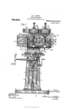
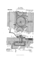
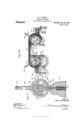
- Figure 1 is a front elevation of a profiler constructed in accordance with this invention
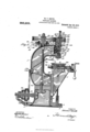
- Fig. '2 a side elevation partly'in section of the same
- Fig. 3 a front elevation of the cutter carriage
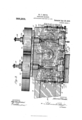
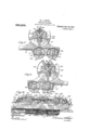
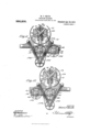
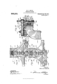
- Fig. 4 a bottom plan view of the cutter carriage; Figs. 5 and 6 top plan views showing the carriage in two positions; Fig. 7 a vertical transverse section of the carriage and support; Fig. 8 a longitudinal section of the carriage and its support online 8- 8 of Fig. 7; Fig. 9 a vertical longitudinal section of the carriage on line 99 of Fig. 7 Fig. 10 a diagrammatic front View of the carriage with its bed 7 plate removed showing the means for moving the cutter spindles vertically; Figs. 11 and 12 top plan views showing a modified form of driving mechanism in two positions; Figs. 13 and 14 top plan viewsshowing a second modification of the driving mechanism in two positions; Fig. 15 is a left hand side elevation of the modification shown in Figs. 13 and 14.
- the profiler comprises, broadly: a main vertical hollow standard constituting the body or support of the entire machine; a horizontal table for holding the work, movable, longitudinally and laterally, and supported upon a vertically movable bracket mounted upon the lower front portion of the frame; a pair of'vertical cutter spindles, vertically movable and carried by a horizontally movable cutter carriage slidably mounted above the table upon the upper front portion of the frame of the machine; a rotary handle, a g'ear'and a rackfor moving each spindle vertically; a'l'atcli for securing the spindles'in fixed positions vertically; a spring for automatically elevatin the spindles'when released from their locked positions; a rotary handle, a'gear and a rack for moving the cutter carriage horizontally; and a latch for locking the carriage in a fixed position.
- the preferred driving mechanism of the machine comprises, broadly: a pair of horizontal pulleys carried upon the upper side of the cutter carriage, concentric respectively with the spindles and having splined connections therewith, so that the spindles may be driven by'the pulleys without supporting them; a vertical shaft extending centrally through the frame of the machine,
- the vertical standard or body 1 of the profiler is provided at its lower end with laterally extending sides 2, having upturned edges 3, and forming the base of the machine.
- the frame of the machine is curved, from a point at the top of the vertical ways supporting the table, rearwardly away from the inner edge of the table, and then extends vertically and is again turned forwardly and extends horizontally above the table, terminating in a substantially vertical flat surface formed by horizontally extending spaced ways or guides 9 which form the upper and lower edges of the front upper portion of the standard and extend longitudinally of the machine, projecting beyond the sides of the standard in each direction, being suitably connected at their ends by cross bars 10, the space between the bars opening into the interior of the standard.
- the cutter carriage which is slidably mounted upon the horizontal ways of the standard has a vertical bed plate 11, the upper side 12 of which is extended inwardly and provided with a groove fitting over the upper edge of the upper guide 9 to support the carriage, the lower side of the carriage being similarly extended over the lower edge of the lower guide.
- each slider mounted upon the front of the carriage bed are a pair of vertically movable sliders 13, the inner side of each slider being formed in the shape of a dovetail ll. and resting in a corresponding groove in the carriage bed.
- the upper and lower ends of each slider are provided with forwardly extending lugs 15, provided with taper sockets and carrying split bearings 16 held in the sockets by means of nuts 17 and lock nuts 18.
- Hotatably supported in these hearings are the vertical cutter spindles 19, the spindles be ing secured against longitudinal movement with respect to their bearings by collars 20 secured to the spindles, or by any other suitable means.
- each spindle passes slidably through a bearing 21, which projects over the front of the bed and is secured to the upper ed e of the bed by means of screws
- This bearing is formed externally into a i upwardly extending cylindrical bearing concentric with the spin lle, and supports a pulley 2%, the hub of which rests at its lower edge upon the shoulder 25 of the beari
- the upper edge of the hub of the pu is provided with a collar 26, secured to the hub by means of screws 27, and projecting over the upper end of the pu ey and slidably receiving the spindles 19, through the aperture of the coi the s .dles being provided with lon diral key-way 28, and the collar being p led with.
- a corresponding spline 28' whereby motion is transmitted from the pulley to the spindle, the spindle being free to slide vertically and the pulley being fixed in a vertical position and being supported dir ctly upon the bed of the carriage.
- a washer 26 Loosely surrounding the spindle and between the collar 26 and the upper end of the bearing 23 is a washer 26 which is rigidly secured to the end of the bearing 23 by means of the screws 27'.
- this washer 26 extends outwardly beyond the surface of the bearing 23 and engages loosely in a recess provided therefor in the upper end of the hub of the pulley
- Vertical movement is given to the spindles by means of the vertical racks (see 8) which are rigidly secured to the bed of the carriage, and gears meshing respectively with the racks, e h of the gears being mounted upon the r end of a shaft 31, which extends rotatably through tl e slider supporting the spindle, in 1-: suitable thimble 82, and has secured to its outer end a crank 33 and c 'ank hanfhe whereby the gear may be rotated, this moving the slider vertic lly and carrying therewith its spindle.
- each gear 30 and rig idly secured to the inner face thereof is a pulleyilfi havinga grooved face 36.
- Extending in the grooves of each pu ley 1* 1d eonnecti the two pulleys togetlter is spir 37, each end of the spi beirg see n its corresponding pulley by means of a plate 38.
- lVhen either pulley is moved out of the horizontal plane of the other. the length of the spring is increased, and the tension upon the spring is suflicient to rotate the lower pulley vertica y along its rack, thus automatically QlGVElt] the corresponding spindle.
- a horizontally movable latch 39 (see Fig. 10) is mounted in guides 40 upon each slider of the cutter carriage and manually operated by means of a bell crank lever .41 pivoted to the slider and having a handle 4-2.
- latch is adapted to engage in a recess 43 of the plate 44, which is secured in a vertical position to the carriage bed adjacent the end of the latch.
- This plate is provided with a vertical groove 45, and secured to the bed plate by means of screws 46 passing through this recess.
- a vertical screw 47 is mounted to rotate on a lug 48 upon the bed and to engage in a lug 49 upon the plate, lock nuts 50 upon the screw being provided to engage against the sides of the lug upon the plate to lock it in any desired position with respect to the screw, the lower end of the screw being retained against longitudinal movement in the lug upon the bed.
- the spindles may be locked in a predetermined position vertically by means of the latch, and the latch plate may be adjusted to change this position according to the requirements of the work.
- Horizontal movement is given to the carriage by means of a horizontal rack 51 (see Figs. 7 and 8) secured to the lower edge of the upper horizontal guide of the standard, and a gear 52 rotatably mounted on the inner side of the carriage, upon the inner end of a shaft 53 extending through the bed plate of the carriage.
- a disk 54 Upon the outer end of the shaft 53 is secured a disk 54 by means of the key 55, the washer 56, and bolt 57 in the end of the shaft.
- the disk is provided with an outwardly extending hub 58 upon which is secured the crank 59 carrying the crank handle 60, the crank being fastened rigidlyto the disk by means of the screw 61.
- the inner face of the disk is provided with an annular groove 62, the outer surface 63 of which forms an internal cam over which rolls the cam follower 64 fixed to the upper end of a vertically movable latch 65, which is slidably mounted in a vertical slot of the bed plate and projects through the bed plate, the inner lower end 66 of the latch projecting over the upper edge of the lower horizontal guide of the standard, and being adapted to engage in a recess 67 in this edge.
- the cam follower actuating the latch is held downwardly against its cam by means of a bolt 68 extending downwardly from the latch through an aperture in the bed plate of the carriage, the upper end of the bolt being fixed into the latch and the lower end of the bolt being provided with a head 69 having a spiral spring 70 surrounding the bolt between the head thereof and the upper shoulder of the enlarged portion of the recess in which the lower end of the bolt and spring are contained.
- the gear 52 upon the inner end of the shaft carrying the crank is provided with a key-way 71 wider than the corresponding key 72, whereby when the crank is rotated in one direction the shaft is permitted to rotate through a limited are before the key 72 acts upon the gear 52 to turn it and to move the carriage.
- Two recesses 67 are provided for the latch to lock the carriage in two positions, and are spaced apart a distance equal to the distance between the cutters, and the gear moving the carriage is so proportioned that one rotation of the gear moves the carriage adistance equal to the space between the cutters, thus giving the cam a complete revolution as the carriage moves over that distance, thus permitting the latch to be drawn by its spring automatically into engagement with each recess consecutively.
- either cutter may I be automatically brought into a fixed position, with respect to the work, with great exactness.
- Power is transmitted to the pulleys connected to the spindles by means of a vertically jointed shaft 73 housed within the standard of the machine.
- the upper end of this vertical shaft projects through an aperture 74 in the upper side of the standard and is carried in a bearing 75 provided intermediate of its ends with a horizontal flange 7 6 resting upon the upper side of the standard and being movably secured thereto by means. of the bolts 7 7 passing through slots 78 in the flange, the bearing being yieldingly pressed toward the front of the ma chine by means of a curved spring 7 9 held against the rear edge of the flange by means of a set screw 80 in an upwardly projecting lug 81 upon the standard.
- this cylindrical bearing 75 is reduced to form a bearing 82 for a driving pulley 83 concentric with the vertical drive shaft 7 3 which projects above the upper edge of the pulley, and is rigidly connected thereto by means of a collor 84, the weight of the pulley and of the shaft being supported by the standard.
- This pulley is so arranged with respect to the pulleys connected to the vertical spindles that as the cutter carriage is moved horizontally it brings the faces of the pulleys consecutively in contact with the driving pulley, and the yielding bearing of the driving pulley prevents any sudden shock or undue stress being brought to bear upon the cutter spindles.
- the lower end of the Vertical drive shaft 78 is supported upon an end thrust roller bearing 85 carried within the frame of the standard, and is provided at its lower end with a bevel gear 86.
- the counter-shaft S7 for driving the machine is mounted on one side of the standard adjacent the base thereof, the inner end of the counter-shaft being journaled in the side of the standard and being provided within the standard with a bevel gear 88 meshing with the bevel gear upon the vertical drive shaft 73 of the machine.
- the outer end of the counter-shaft is journaled at the upper end of a bracket 89, the lower end of which is fastened to the outer edge of the base of the machine.
- the countershaft carries the usual cone pulley 90, to be connected to a main driving shaft, and also a pulley 91 to drive the oiling pump.
- Means for keeping the cutters constantly lubricated is provided within the standard and comprises an oil tank 92, a rotary pump 93, a pipe 941 between the tank and the pump and a pipe 95 leading from the pump to the front side of the standard and having a jointed end 96 to direct the flow of oil against the cutter.
- the oil tank is located in the front lower side of the standard just beneath the shoulder below the table. the upper surface of the shoulder being dished and provided with an aperture 97 leading from the bottom of the depressed portion of the surface into the top of the oil tank.
- the table also is provided with a groove 98 extending around the upper surface thereof to catch the oil as it flows from the cutter and to return the same through the groove and over the in clined surface 99 of the bed of the table into the basin and through the aperture 97 of the standard and into the oil tank 92.
- the oil pump has its spindle 100, projecting through the side of the standard and carries apulley 101 vertically in alinement with the pulley 91 upon the counter-shaft by which it is driven.
- Figs. 11 and 12 are shown two positions of a modified form of mechanism for driving this machine.
- This construction comprises pulleys, 102, as already described, connected to the upper ends of the vertical cutter spindles, and also a driving pulley 103 as already described connected to the upper end of a vertical drive shaft carried by the standard, but the pulley 103 is spaced from the pulleys 102 so as not to be broughtinto contact with the rims of either of these pulleys through the motion of the carriage, and a belt 10 1 passing around pulley 108 and between pulleys 102 and over an idler 104 supported upon arms 105 rigid with the standard is used to drive the pulleys 102.
- an idler, 106 is mounted upon a sliding bearing 107 between the main driving pulley 108 and the pulleys 109 connected to the spindles, and the belt 110 in this case passing over the main driving pulley 108 and around the outer sides of the pulleys driving the spindles being brought inwardly between these latter pulleys and carried around the idler.
- the idler is drawn rearwardly to maintain the belt always in tight condition by means of a rope 111 connected to the sliding bearing of the pulley and extending rearwardly over a pulley 112 and then downwardly and having a weight 113 connected to its lower end.
- the work is clan'iped to the table of the machine to which is also attached the pattern or model to be duplicated and the cutters are adjusted and the carriage is moved to bring the roughing cutter and the finishing cutter consecutively into locked operative position with respect to the table.
- the sliders earrying the cutters are each provided with pins, 114, arranged upon opposite sides of the cutter and adapted to serve as guides for manipulating the table to bring the various portions of the pattern beneath the point of one of the pins, thereby moving the work correspondingly beneath the cutter to reproduce the contour of the pattern.
- a profiler the combination with a standard, provided with spaced ways, of a cutter carriage slidably mounted upon said ways, a rack secured to the inner edge of one of said ways, a gear rotatably carried by said carriage upon the inner side thereof and meshing with said rack, and means to rotate said gear to move said carriage.
- a profiler the combination with a standard provided with spaced ways, of a cutter carriage slidably mounted upon said w ays, a rack secured to the inner edge of one of said ways, a gear rotatably carried by said carriage and meshing with said rack, means to rotate said gear to move said carriage, and a latch upon said carriage and actuated by said rotating means to engage a recess provided therefor in said standard to lock said carriage in a predetermined position.
- a profiler the combination with a standard, provided with spaced ways, of a cutter carriage slidably mounted upon said ways, a rack secured to the edge of one of said ways, a shaft extending through said carriage and rotatably carried thereby, a gear fixed upon the inner end of said shaft and meshing with said rack, a cam fixed upon said shaft, a latch actuated by said cam and adapted to engage a recess provided therefor in said standard to lock said carriage in a predetermined position, and means to turn said gear to move and to lock said carriage.
- a profiler the combination with a standard, of a cutter carriage movably mounted thereon, a rack secured to said standard, a rotatable shaft mounted upon said carriage, a gear meshing with said rack and fixed upon said shaft, a disk provided with an annular groove forming a cam secured to said shaft, a latch slidably mounted upon said carriage and adapted to engage with said standard, a follower secured to said latch and engaging against said cam, and means to turn said shaft to move and to automatically lock said carriage.
- the combination wlth a standard, of a movable carriage mounted thereon, means for locking the said carriage in a predetermined position, and a member for moving said carriage into and out of locking engagement with said standard, said member being movable through a predetermined space to unlock the carriage without effecting the movement of the carriage.
- a profiler the combination with a standard, of a movable carriage mounted thereon, a rack secured to said standard, a gear meshing with said rack, a shaft carrying said gear and rotatably mounted upon the carriage, said gear being free to rotate through a limited are with respect to said shaft, a latch slidably mounted upon said carriage, means upon said shaft for actuating said latch, said latch being adapted to engage in a recess provided therefor in said standard, and means to rotate said shaft to move and to lock said carriage.
- a latch slidably mounted in a slot in said bed plate extending through said plate, the outer end of said latch being provided with a follower engaging against said cam surface, the inner end of said latch being adapted to engage in a recess provided therefor in the edge of one of said ways, and means to rotate said shaft to move and to lock said carriage.
- a carriage means to lock said carriage in one position, a crank and means operated by one revolution of said crank to unlock said carriage and to move it to a second position, and to then lock the carriage in said second position.
- a cutter carriage In a profiler, a cutter carriage, a pair of spaced cutter spindles and rotatable means for moving said carriage by a single rotation of said means a distance equal to the space between the axes of said spindles.
- a profiler the combination with a standard, of a horizontal table mounted upon a vertically adjustable bracket slidably mounted upon the front lower side of said standard, said table being longitudinally and laterally movable, said standard being recessed to receive the inner edge of said table, a horizontally movable cutter carriage slidably mounted upon said standard above said table, vertical spindles rotatably mounted upon said carriage and vertically movable thereon, pulleys mounted upon said carriage and splined to said spindles for driving the same, means to move said carriage horizontally, means to move said spindles vertically, a shaft having its lower end mounted.
- a bearing for the upper end of said vertical shaft slidably mounted upon the upper side of said standard over an aper ture provided therein, said shaft extending upwardly through said bearing and being provided at its upper end with a collar rigid therewith, a pulley rotatably mounted upon said movable bearing and secured to said collar and adapted to engage successively against the pulleys driving said spindles, a spring to force said movable bearing toward said spindles, and means to drive said vertical shaft to actuate said machine.
- a carriage in a profiler, a carriage, a pair of parallel spaced cutter spindles carried thereby, and rotatable means for moving said carriage by a single rotation of said means, a distance equal to the distance between the axes of said spindles.
- a hollow standard of a table supported there by, a pump and an oil tank within said standard, a tube leading from said tank to said pump and from said pump through the side of said standard, and terminating over said table to deliver oil thereon
- said standard being provided with an apertured recess over said tank
- said table being provided with inclined surfaces leading toward said recess to turn the oil from said table to said tank
- a counter-shaft for supplying power for said profiler
- a spindle extending through the side of said standard for driving said pump, and means upon the outside of said standard between said standard and said counter-shaft to drive said spindle.
- a protilcr the combination with a standard, of a cutter carriage movable thereon, a pair of sliders supported upon said carriage, spindles mounted upon said sliders, a rack upon said carriage adjacent to each slider, a gear meshing with each rack and rotatably carried by each of said sliders, a pulley with a grooved face concentric with each of said pulleys, and a yielding member carried in the said grooves and connecting said pulleys to retract said spindles after said spindles have been displaced.
- a profiler the combination with a hollow standard, of a table supported there by, a pump and a tank within said standard, a pipe leading from said tank to said pump and from said pump over said table to deliver a liquid upon said table, a spindle extending through the side of said standard for driving said pump and means upon the outside of said standard to drive said spindle, said table being grooved to return the liquid to said tank.
- a profiler the combination with a hollow standard, of a table supported thereby, a pump and a tank within said standard, a pipe leading from said tank to said pump and from said pump over said table and terminating in a jointed end adapted to deliver a liquid upon said table, and means carried by said standard for driving said pump.
- a profiler the combination with a bearing having concentric external and internal bearing surfaces, of a spindle rotatably mounted within said bearing and proj ecting therefrom, a pulley rotatably mounted upon the external surface of said bearing and a collar slidingly splined to said spindle and connected to the end of said pulley, said bearing bein fixed at one end and extending freely therefrom, and said pulley being removable over the free end of said bearing.
- a profiler the combination with a hollow vertical standard, having a recess in the front thereof, of a table supported by said standard and having its inner edge within said recess, the surface upon the under side of said recess beneath said table, being inclined toward an a erture through said standard and a tank within said standard beneath said aperture.
- a profiler the combination with a bearing, having concentric external and internal bearing surfaces, of a spindle rota tably mounted within said bearing and projecting therefrom, a pulley rotatably mounted upon the external surface of said bearing, a collar slidingly splined to said spindle and connected to the end of said pulley and a washer removably secured to the end of said bearing and loosely engaging in a recess provided therefor in the end of said pulley to hold said pulley against movement longitudinally of its hearing.
Landscapes
- Engineering & Computer Science (AREA)
- Automation & Control Theory (AREA)
- Mechanical Engineering (AREA)
- Control Of Cutting Processes (AREA)
Description
WITNESSES M. P. SMITH.
PROEILING MACHINE; AIPPLIOATION I'ILEDSEPT. 30, 1907.
s exams-sum 1.
,INVENTOR' ATTORNEY ANDREW a GRAHAM co.. FuOTo-Lnucsmwms WASHINGTON. .0-
Patelited Apr. 26, 1910;
"M.- F. SMITH.
v v PROPILING MACHINE. v
' APPLICATION FILED SEPT. 30, 1907. 956,209, Batented Apr.26,1910. s SHEETS-SHEET 2.
ANDREW B cnmmm c0. PHOTOYUTHOGHAPNERS. WASHINGTON. o. r:
? vzllllllllll WITNESSES M. P. SMITH; PROFILING MACHINE. APPLIOATION FILED SEPT. 30 1907.
Patented Apr. 26, 1910.
8 SHEETS-SHEET 3.
' WITNEISSQESY A TTORNEY A'nnnzw a GRAHAM cu, FHOTO-LITHOGRA M. F. SMITH. PROPILING MAGHINE.
.A BPLIOATION FILED BERT. 30, 190]. 956,209. I
8 SHEETS-SHEET 4. I
A TTORNEY Patented A r. 26, 1910.
vM. F. SMITH. PROFILING MAGHINB.
A l, A hv 1 H u bk m1 w: R T I I Mm h rb m 8 \b m6 m w M n P Why m x: mm mk v t m bk M HHTi B V m R, hhh L w W m E m Nb m mm \WXJ A Q L Q A TTORNEY ERS, WASHING M. F. SMITH.
PROPILING MAGHINE. APPLIOA TION TILED SEPT. 30, 1907.
A TTORNEY ggyrNEssEs I AyoREw a GRAHAM co. FHOTOLITNCGRAPNERS, wAaamGTuM n c.
. Ml 1*. SMITH. PROPILING MAUHINE.
, 'APPLIGATION FILED SEPT. 307 1907'. Apr.
'8 SHBBTS-SHBET 7.
- I I INVEN-TQR Mafia/7671146? WITNESSES I 4 BY W AT fORNEY ANDREW u. GR-AHAM cu r-nowmmocmwzns WASHINGTON u/c M. P. SMITH. PROFILING MACHINE. APPLICATION FILED SEPT. 30, 1907.
Patented Apr. 26, 1910.
INVENTOR WITNESSES fiy By ATTORNEY UNITED TAT S; OFFICE.-
MORRIS F. SMITH, PHILADELPHIA, PENNSYLVANIA, ASSIGNOR COMPANY A CORPORATION OF 'DELAKTAREL T0 s'riinnann ARMS PROFIIING-MAOHINE.
Specification of Letters Patent. Patented Apr, 26 1910, Application filed September 30, 1907. Serial No. 395,160.
To all whom it may concern:
Be it known that I, MORRIS F. SMITH, a citizen of the United States, and a resident of the city of Philadelphia, county of Phil'- adelphia, and State of Pennsylvania, have invented certain new and useful Improvements in Profiling-Machines, of which the following is a full, clear, and exact description.
My invention relates to improvements in profilers, and particularly to that class of profilers in which a cutter is guided through a predetermined path by means of a pin which is moved over a fixed templet.
Profiling machines usually have two or more cutters, including a roughing cutter and a finishing cutter, actuated by separate spindles; the roughing cutter being used first to reduce the work to approximately the desired shape, this cutter then being moved out of position and the finishing cutter being brought into position to complete the operation. I-Ieretofore these cutters have both been driven simultaneously, although only one of the cutters could be used at a time; thus needless power was consumed in driving the idle cutter and there was unnecessary wearing of the parts of the machine not performing any useful function.
The main objects of myinvention are to provide a profiler with the following improvements; driving mechanism by which a cutter is driven only when in operative position; mechanism by which a cutter may be quickly and conveniently moved into or out of a predetermined fixed operative position; a counterbalance for each cutter so that when the cutter is released from its lowermost operative position it will be automatically raised to its uppermost inoperative position; means for preventing undue wear and shock upon the cutters; means for raising and lowering the cutters; means for moving the cutters laterally; an automatic system inclosed within the standard of the profiler for lubricating the cutters; and other improvements which will appear in the following specification.
In the accompanying drawings: Figure 1 is a front elevation of a profiler constructed in accordance with this invention; Fig. '2 a side elevation partly'in section of the same; Fig. 3 a front elevation of the cutter carriage;
Fig, 4 a bottom plan view of the cutter carriage; Figs. 5 and 6 top plan views showing the carriage in two positions; Fig. 7 a vertical transverse section of the carriage and support; Fig. 8 a longitudinal section of the carriage and its support online 8- 8 of Fig. 7; Fig. 9 a vertical longitudinal section of the carriage on line 99 of Fig. 7 Fig. 10 a diagrammatic front View of the carriage with its bed 7 plate removed showing the means for moving the cutter spindles vertically; Figs. 11 and 12 top plan views showing a modified form of driving mechanism in two positions; Figs. 13 and 14 top plan viewsshowing a second modification of the driving mechanism in two positions; Fig. 15 is a left hand side elevation of the modification shown in Figs. 13 and 14.
The profiler comprises, broadly: a main vertical hollow standard constituting the body or support of the entire machine; a horizontal table for holding the work, movable, longitudinally and laterally, and supported upon a vertically movable bracket mounted upon the lower front portion of the frame; a pair of'vertical cutter spindles, vertically movable and carried by a horizontally movable cutter carriage slidably mounted above the table upon the upper front portion of the frame of the machine; a rotary handle, a g'ear'and a rackfor moving each spindle vertically; a'l'atcli for securing the spindles'in fixed positions vertically; a spring for automatically elevatin the spindles'when released from their locked positions; a rotary handle, a'gear and a rack for moving the cutter carriage horizontally; and a latch for locking the carriage in a fixed position. i
The preferred driving mechanism of the machine comprises, broadly: a pair of horizontal pulleys carried upon the upper side of the cutter carriage, concentric respectively with the spindles and having splined connections therewith, so that the spindles may be driven by'the pulleys without supporting them; a vertical shaft extending centrally through the frame of the machine,
journaled in-bearings carried thereby, havdrive shaft by inter-meshing bevel 'ears to drive the machine.
Referring to the drawings, particularly to Figs. 1 and 2, it is seen that the vertical standard or body 1 of the profiler is provided at its lower end with laterally extending sides 2, having upturned edges 3, and forming the base of the machine. The lower front portion of the standard is provided with vertical parallel ways l, upon which is slidably mounted a bracket 5, which is provided upon its upper side with ways (3 extending l1e"'=izo"ally in av direction substentiri erpc scalar to the front plane of the machine, and slidably carrying table bed 7, supporting upon its upper side the table 8 which is mounted to slide, with respect to the bed, direction parallel to the front plane of the machine. The usual mechanism is provided for elevating the table by raising the bracket supporting it, and for moving the table either longitudi nally or laterally of the machine. Such mechanism being old, a full detailed description is not necessary, as this feature of the machine will be sufficiently understood from the drawings.
The frame of the machine is curved, from a point at the top of the vertical ways supporting the table, rearwardly away from the inner edge of the table, and then extends vertically and is again turned forwardly and extends horizontally above the table, terminating in a substantially vertical flat surface formed by horizontally extending spaced ways or guides 9 which form the upper and lower edges of the front upper portion of the standard and extend longitudinally of the machine, projecting beyond the sides of the standard in each direction, being suitably connected at their ends by cross bars 10, the space between the bars opening into the interior of the standard.
The cutter carriage, which is slidably mounted upon the horizontal ways of the standard has a vertical bed plate 11, the upper side 12 of which is extended inwardly and provided with a groove fitting over the upper edge of the upper guide 9 to support the carriage, the lower side of the carriage being similarly extended over the lower edge of the lower guide.
Mounted upon the front of the carriage bed are a pair of vertically movable sliders 13, the inner side of each slider being formed in the shape of a dovetail ll. and resting in a corresponding groove in the carriage bed. The upper and lower ends of each slider are provided with forwardly extending lugs 15, provided with taper sockets and carrying split bearings 16 held in the sockets by means of nuts 17 and lock nuts 18. Hotatably supported in these hearings are the vertical cutter spindles 19, the spindles be ing secured against longitudinal movement with respect to their bearings by collars 20 secured to the spindles, or by any other suitable means. The upper end of each spindle passes slidably through a bearing 21, which projects over the front of the bed and is secured to the upper ed e of the bed by means of screws This bearing is formed externally into a i upwardly extending cylindrical bearing concentric with the spin lle, and supports a pulley 2%, the hub of which rests at its lower edge upon the shoulder 25 of the beari The upper edge of the hub of the pu is provided with a collar 26, secured to the hub by means of screws 27, and projecting over the upper end of the pu ey and slidably receiving the spindles 19, through the aperture of the coi the s .dles being provided with lon diral key-way 28, and the collar being p led with. a corresponding spline 28' whereby motion is transmitted from the pulley to the spindle, the spindle being free to slide vertically and the pulley being fixed in a vertical position and being supported dir ctly upon the bed of the carriage. Loosely surrounding the spindle and between the collar 26 and the upper end of the bearing 23 is a washer 26 which is rigidly secured to the end of the bearing 23 by means of the screws 27'. The outer --dge of this washer 26 extends outwardly beyond the surface of the bearing 23 and engages loosely in a recess provided therefor in the upper end of the hub of the pulley Vertical movement is given to the spindles by means of the vertical racks (see 8) which are rigidly secured to the bed of the carriage, and gears meshing respectively with the racks, e h of the gears being mounted upon the r end of a shaft 31, which extends rotatably through tl e slider supporting the spindle, in 1-: suitable thimble 82, and has secured to its outer end a crank 33 and c 'ank hanfhe whereby the gear may be rotated, this moving the slider vertic lly and carrying therewith its spindle. Concentricwith each gear 30 and rig idly secured to the inner face thereof is a pulleyilfi havinga grooved face 36. Extending in the grooves of each pu ley 1* 1d eonnecti the two pulleys togetlter is spir 37, each end of the spi beirg see n its corresponding pulley by means of a plate 38. lVhen either pulley is moved out of the horizontal plane of the other. the length of the spring is increased, and the tension upon the spring is suflicient to rotate the lower pulley vertica y along its rack, thus automatically QlGVElt] the corresponding spindle.
A horizontally movable latch 39 (see Fig. 10) is mounted in guides 40 upon each slider of the cutter carriage and manually operated by means of a bell crank lever .41 pivoted to the slider and having a handle 4-2. The
latch is adapted to engage in a recess 43 of the plate 44, which is secured in a vertical position to the carriage bed adjacent the end of the latch. This plate is provided with a vertical groove 45, and secured to the bed plate by means of screws 46 passing through this recess. To conveniently adjust the latch plate 44, a vertical screw 47 is mounted to rotate on a lug 48 upon the bed and to engage in a lug 49 upon the plate, lock nuts 50 upon the screw being provided to engage against the sides of the lug upon the plate to lock it in any desired position with respect to the screw, the lower end of the screw being retained against longitudinal movement in the lug upon the bed. By this arrangement the spindles may be locked in a predetermined position vertically by means of the latch, and the latch plate may be adjusted to change this position according to the requirements of the work.
Horizontal movement is given to the carriage by means of a horizontal rack 51 (see Figs. 7 and 8) secured to the lower edge of the upper horizontal guide of the standard, and a gear 52 rotatably mounted on the inner side of the carriage, upon the inner end of a shaft 53 extending through the bed plate of the carriage. Upon the outer end of the shaft 53 is secured a disk 54 by means of the key 55, the washer 56, and bolt 57 in the end of the shaft. The disk is provided with an outwardly extending hub 58 upon which is secured the crank 59 carrying the crank handle 60, the crank being fastened rigidlyto the disk by means of the screw 61. The inner face of the disk is provided with an annular groove 62, the outer surface 63 of which forms an internal cam over which rolls the cam follower 64 fixed to the upper end of a vertically movable latch 65, which is slidably mounted in a vertical slot of the bed plate and projects through the bed plate, the inner lower end 66 of the latch projecting over the upper edge of the lower horizontal guide of the standard, and being adapted to engage in a recess 67 in this edge. The cam follower actuating the latch is held downwardly against its cam by means of a bolt 68 extending downwardly from the latch through an aperture in the bed plate of the carriage, the upper end of the bolt being fixed into the latch and the lower end of the bolt being provided with a head 69 having a spiral spring 70 surrounding the bolt between the head thereof and the upper shoulder of the enlarged portion of the recess in which the lower end of the bolt and spring are contained. By this arrangement when the crank is turned to move the carriage horizontally the latch locking the carriage will be automatically withdrawn from engagement with the standard during the first part of the turn of the crank, to permit the carriage to be moved, and during the last part of the turn of the crank the latch will be permitted to be drawn by its s ring into engagement against the edge 0 the guide along which it will slide until it drops into a second recess provided to lock the carriage in its second position.
Toprevent the movement of the carriage until the latch is withdrawn, the gear 52 upon the inner end of the shaft carrying the crank is provided with a key-way 71 wider than the corresponding key 72, whereby when the crank is rotated in one direction the shaft is permitted to rotate through a limited are before the key 72 acts upon the gear 52 to turn it and to move the carriage. Two recesses 67 are provided for the latch to lock the carriage in two positions, and are spaced apart a distance equal to the distance between the cutters, and the gear moving the carriage is so proportioned that one rotation of the gear moves the carriage adistance equal to the space between the cutters, thus giving the cam a complete revolution as the carriage moves over that distance, thus permitting the latch to be drawn by its spring automatically into engagement with each recess consecutively. Thus when the machine is once adjusted either cutter may I be automatically brought into a fixed position, with respect to the work, with great exactness.
Power is transmitted to the pulleys connected to the spindles by means of a vertically jointed shaft 73 housed within the standard of the machine. The upper end of this vertical shaft projects through an aperture 74 in the upper side of the standard and is carried in a bearing 75 provided intermediate of its ends with a horizontal flange 7 6 resting upon the upper side of the standard and being movably secured thereto by means. of the bolts 7 7 passing through slots 78 in the flange, the bearing being yieldingly pressed toward the front of the ma chine by means of a curved spring 7 9 held against the rear edge of the flange by means of a set screw 80 in an upwardly projecting lug 81 upon the standard. The upper end of this cylindrical bearing 75 is reduced to form a bearing 82 for a driving pulley 83 concentric with the vertical drive shaft 7 3 which projects above the upper edge of the pulley, and is rigidly connected thereto by means of a collor 84, the weight of the pulley and of the shaft being supported by the standard. This pulley is so arranged with respect to the pulleys connected to the vertical spindles that as the cutter carriage is moved horizontally it brings the faces of the pulleys consecutively in contact with the driving pulley, and the yielding bearing of the driving pulley prevents any sudden shock or undue stress being brought to bear upon the cutter spindles.
The lower end of the Vertical drive shaft 78 is supported upon an end thrust roller bearing 85 carried within the frame of the standard, and is provided at its lower end with a bevel gear 86.
The counter-shaft S7 for driving the machine is mounted on one side of the standard adjacent the base thereof, the inner end of the counter-shaft being journaled in the side of the standard and being provided within the standard with a bevel gear 88 meshing with the bevel gear upon the vertical drive shaft 73 of the machine. The outer end of the counter-shaft is journaled at the upper end of a bracket 89, the lower end of which is fastened to the outer edge of the base of the machine. The countershaft carries the usual cone pulley 90, to be connected to a main driving shaft, and also a pulley 91 to drive the oiling pump.
Means for keeping the cutters constantly lubricated is provided within the standard and comprises an oil tank 92, a rotary pump 93, a pipe 941 between the tank and the pump and a pipe 95 leading from the pump to the front side of the standard and having a jointed end 96 to direct the flow of oil against the cutter. The oil tank is located in the front lower side of the standard just beneath the shoulder below the table. the upper surface of the shoulder being dished and provided with an aperture 97 leading from the bottom of the depressed portion of the surface into the top of the oil tank. The table also is provided with a groove 98 extending around the upper surface thereof to catch the oil as it flows from the cutter and to return the same through the groove and over the in clined surface 99 of the bed of the table into the basin and through the aperture 97 of the standard and into the oil tank 92. Thus a steady circulation of the oil is maintained from the tank to the cutter and back again to the tank. The oil pump has its spindle 100, projecting through the side of the standard and carries apulley 101 vertically in alinement with the pulley 91 upon the counter-shaft by which it is driven.
In Figs. 11 and 12 are shown two positions of a modified form of mechanism for driving this machine. This construction comprises pulleys, 102, as already described, connected to the upper ends of the vertical cutter spindles, and also a driving pulley 103 as already described connected to the upper end of a vertical drive shaft carried by the standard, but the pulley 103 is spaced from the pulleys 102 so as not to be broughtinto contact with the rims of either of these pulleys through the motion of the carriage, and a belt 10 1 passing around pulley 108 and between pulleys 102 and over an idler 104 supported upon arms 105 rigid with the standard is used to drive the pulleys 102. By a comparative inspection of Figs. 11 and 12 it will be seen that as the carriage is moved from right to left the pulleys 102 driving the cutter spindles are successively engaged and driven by opposite portions of the belt 10* In the modified driving mechanism shown in Figs. 13, 14. and 15, an idler, 106, is mounted upon a sliding bearing 107 between the main driving pulley 108 and the pulleys 109 connected to the spindles, and the belt 110 in this case passing over the main driving pulley 108 and around the outer sides of the pulleys driving the spindles being brought inwardly between these latter pulleys and carried around the idler. The idler is drawn rearwardly to maintain the belt always in tight condition by means of a rope 111 connected to the sliding bearing of the pulley and extending rearwardly over a pulley 112 and then downwardly and having a weight 113 connected to its lower end.
In the operation of this profiler, the work is clan'iped to the table of the machine to which is also attached the pattern or model to be duplicated and the cutters are adjusted and the carriage is moved to bring the roughing cutter and the finishing cutter consecutively into locked operative position with respect to the table. The sliders earrying the cutters are each provided with pins, 114, arranged upon opposite sides of the cutter and adapted to serve as guides for manipulating the table to bring the various portions of the pattern beneath the point of one of the pins, thereby moving the work correspondingly beneath the cutter to reproduce the contour of the pattern.
Having thus fully described my invention, what I claim and desire to protect by Letters Patent of the United States is:
1. In a profiler, the combination with a standard, of a movable cutter carriage carried thereby, a rack rigid with said standard, a gear rotatably carried by said carriage, and means for rotating said gear to move said carriage.
2. In a profiler, the combination with a standard, of a movable cutter carriage, a rack rigid with said standard, a gear rotatably carried by said carriage, and means for rotating said gear to move said carriage.
3. In a profiler, the combination with a standard, of a movable cutter carriage carried thereby, a rack rigid with said standard, a gear rotatably supported by said carriage meshing with said rack, means to rotate said gear to move said carriage, and means actuated by said rotating means to lock said carriage in a predetermined position.
at. In a profiler, the combination with a standard, of a movable cutter carriage carried thereby, a rack rigid with said standard, a gear rotatably supported by said carriage meshing with said rack, means to rotate said gear to move said carriage, and a latch mounted upon said carriage and actuated by said rotating means to lock said carriage in a predetermined position.
5. In a profiler, the combination with a standard, of a movable cutter carriage carried thereby, a rack rigid with said stand-- ard, a gear rotatably supported by said carriage meshing with said rack, means to rotate said gear to move said carriage, and a latch slidably mounted upon said carriage and actuated by said rotating means, and arranged and adapted to engage in a recess provided therefor in said standard to lock said carriage in a predetermined position.
6. In a profiler, the combination with a standard, provided with a way, of a cutter carriage slidably mounted upon said way, a rack secured to said way, a gear rotatably carried by said carriage and meshing with said rack, and means to rotate said gear to move said carriage.
7. In a profiler, the combination with a standard, provided with spaced ways, of a cutter carriage slidably mounted upon said ways, a rack secured to the inner edge of one of said ways, a gear rotatably carried by said carriage and meshing with said rack, and means to rotate said gear to move said carriage.
8. I11 a profiler, the combination with a standard, provided with spaced ways, of a cutter carriage slidably mounted upon said ways, a rack secured to the inner edge of one of said ways, a gear rotatably carried by said carriage upon the inner side thereof and meshing with said rack, and means to rotate said gear to move said carriage.
9. In a profiler, the combination with a standard, provided with spaced ways, of a cutter carriage slidably mounted upon said ways, a rack secured to the inner edge of one of said ways, a gear rotatably carried by said carriage and meshing with said rack, means to rotate said gear to move said carriage, and means actuated by .said rotating means to lock said carriage in a predetermined position.
10. In a profiler, the combination with a standard provided with spaced ways, of a cutter carriage slidably mounted upon said w ays, a rack secured to the inner edge of one of said ways, a gear rotatably carried by said carriage and meshing with said rack, means to rotate said gear to move said carriage, and a latch upon said carriage and actuated by said rotating means to engage a recess provided therefor in said standard to lock said carriage in a predetermined position.
11. In a profiler, the combination with a standard provided with spaced ways, of a cutter carriage slidably mounted upon said ways, a rack secured to the inner edge of one of said ways, a shaft extending through said carriage and rotatably carried thereby,
a gearfixed upon the inner edge of said shaft meshing with said rack, a cam fixed upon said shaft, a latch actuated by said cam to engage said standard to lock said carriage in a predetermined position, and means to rotate saidshaft to move and to lock said carriage.
12. In a profiler, the combination with a standard, provided with spaced ways, of a cutter carriage slidably mounted upon said ways, a rack secured to the edge of one of said ways, a shaft extending through said carriage and rotatably carried thereby, a gear fixed upon the inner end of said shaft and meshing with said rack, a cam fixed upon said shaft, a latch actuated by said cam and adapted to engage a recess provided therefor in said standard to lock said carriage in a predetermined position, and means to turn said gear to move and to lock said carriage.
13. In a profiler, the combination with a standard provided with horizontal spaced ways, of a cutter carriage slidably mounted upon said ways, a rack secured to the lower edge of the upper of said ways, a shaft extending through said carriage and rotatably carried thereby, a gear fixed upon the inner end of said shaft and meshing with said rack, a cam fixed upon said shaft, a spring latch actuated by said cam and adapted to engage a recess provided therefor in said standard to lock said carriage in a predetermined position, and means to turn said gear to move and to lock said carriage.
14. In a profiler, the combination with a standard, of a cutter carriage movably mounted thereon, a rack secured to said standard, a rotatable shaft mounted upon said carriage, a gear meshing with said rack and fixed upon said shaft, a disk provided with an annular groove forming a cam secured to said shaft, a cam follower engaging said cam, and means actuated by said cam follower to lock said carriage.
15. In a profiler, the combination with a standard, of a cutter carriage movably mounted thereon, a rack secured to said standard, a rotatable shaft mounted upon said carriage, a gear meshing with said rack and fixed upon said shaft, a disk provided with an annular groove forming a cam secured to said shaft, a latch slidably mounted upon said carriage and adapted to engage with said standard, a follower secured to said latch and engaging against said cam, and means to turn said shaft to move and to automatically lock said carriage.
16. In a profiler, the combination with a standard, of a cutter carriage movably mounted thereon, a rack secured to said standard, a rotatable shaft mounted upon said carriage, a gear meshing with said rack and fixed upon said shaft, a disk provided with an annular groove forming a cam fixed on said shaft, a latch slidably mounted upon said carriage and adapted to engage with said standard, a follower secured to said latch and engaging against said cam, a spring between said latch and said carriage to hold said cam follower 111 engagement with said cam, and means to turn said shaft to move and to automatically lock said carriage.
17. In a profiler, the combination wlth a standard, of a movable carriage mounted thereon, means for locking the said carriage in a predetermined position, and a member for moving said carriage into and out of locking engagement with said standard, said member being movable through a predetermined space to unlock the carriage without effecting the movement of the carriage.
18. In a profiler, the combination with a standard, of a movable carriage mounted thereon, a rack secured to said standard, a gear meshing with said rack, a shaft carrying said gear and rotatably mounted upon the carriage, said gear being free to rotate through a limited are with respect to said shaft, a latch slidably mounted upon said carriage, means upon said shaft for actuating said latch, said latch being adapted to engage in a recess provided therefor in said standard, and means to rotate said shaft to move and to lock said carriage.
19. In a profiler, the combination with a standard, of a movable carriage mounted thereon, a rack secured to said standard, a gear meshing with said rack, a shaft carry 111g said gear and rotatably mounted upon the carriage, said gear being free to rotate through a limited arc with respect to said shaft, and means actuated by said shaft for locking said carriage.
20. In a profiler, the combination with a standard, of a movable carriage mounted thereon, a rack secured to said standard, a gear meshing with said rack, a shaft carrying said gear and rotatably mounted upon said carriage, a key engaging in a key way provided therefor wider than said key be tween said shaft and said gear, whereby said gear is restrained to rotate through a limited are upon said shaft, and means actuated by said shaft to lock said carriage.
21. In a profiler, the combination with a standard provided with spaced ways, of a carriage slidably mounted upon said ways, a rack upon the inner edge of one of said ways, a gear upon the inner side of said bed plate meshing with said rack, a shaft through said bed plate and carrying upon its inner end said gear, said shaft being provided with a key and said gear with a key-way wider than said key, whereby said gear is restrained to rotate through a limited are upon said shaft, a disk fixed upon the front of said bed plate, said disk being provided with an internal annular groove forming a cam upon the outer surface of the groove,
a latch slidably mounted in a slot in said bed plate extending through said plate, the outer end of said latch being provided with a follower engaging against said cam surface, the inner end of said latch being adapted to engage in a recess provided therefor in the edge of one of said ways, and means to rotate said shaft to move and to lock said carriage.
2 In a profiler, the combination with a standard, provided with horizontal spaced ways, of a carriage having a substantially flat vertical bed plate slidably mounted upon said ways, a rack upon the lower edge of the upper of said ways, a gear upon the inner side of said bed plate meshing with said rack, a shaft extending through said bed plate and carrying upon its inner end said gear, said shaft being provided with a key and said gear with a key-way wider than said key, whereby said gear is restrained to rotate through a limited are upon said. shaft, a disk fixed upon the front side of said bed plate, said disk being provided with an internal annular groove forming upon the outer surface of said groove a cam, a spring retained latch slidably mounted in a vertical slot in said bed plate beneath said shaft and extending through said plate, the outer and upper end of said latch being provided with a follower engaging against said cam surface, the inner and lower end of said latch being arranged above the lower of said ways and adapted to engage in a recess provided therefor in the upper edge thereof, and means to rotate said shaft to move and to lock said carriage.
23. In a profiler, a carriage, means to lock said carriage in one position, a crank and means operated by one revolution of said crank to unlock said carriage and to move it to a second position, and to then lock the carriage in said second position.
24. In a profiler, a cutter carriage, a pair of spaced cutter spindles and rotatable means for moving said carriage by a single rotation of said means a distance equal to the space between the axes of said spindles.
25. In a profiler, the combination with a standard, of a cutter carriage horizontally movable thereon, a slider vertically mo 'able upon said carriage, a cutter spindle rotatably mounted upon said slider, a latch mounted upon said slider to lock said slider in a fixed position vertically, a plate mounted upon said carriage and provided with a recess adapted to engage one end of said latch, and means to adjust said plate vertically, said means comprisinga vertical screw between said carriage and said plate.
26. In a profiler, the combination with a standard, of a cutter carriage horizontally movable upon said standard, a vertical cutter spindle rotatably mounted upon said carriage and vertically movable thereon, a vertical rack secured to said standard, a gear meshing with said rack, and means to rotate said gear along said rack to move said spindle vertically.
27. In a profiler, the combination with a standard, of a cutter carriage horizontally movable upon said standard, a slider vertically movable upon said carriage,avertical spindle rotatably mounted upon said slider, a vertical rack upon said standard, a gear meshing with said rack and rotatably carried by said slider, and means to rotate said gear to move said spindle vertically.
28. In a profiler, the combination with a cutter carriage, of a longitudinally movable cutter spindle rotatably mounted thereon, a rack upon said carriage adjacent said spindle, a gear meshing with said rack and rotated by the longitudinal movement of said spindle, a pulley actuated by said gear, and a spring carried on the face of said pulley to retract said spindle when moved longitudinally.
29. In a profiler, the combination with a cutter carriage, of a series of longitudinally movable cutter spindles rotatably mounted upon said carriage, a rack upon said carriage adjacent each spindle, a gear meshing with each rack and rotated by the longitudinal movement of each spindle respectively, and means between said gears to retract said spindles when moved longitudinally.
30. In a profiler, the combination with a standard, of a movable cutter carriage mounted thereon, a pair of cutter spindles rotatably mounted upon said carriage and longitudinally movable thereon, a rack upon said carriage adjacent each spindle, a gear meshing with each rack and rotated by the longitudinal movement of each spindle respectively, a pulley with a grooved face concentric with each of said gears, and a spring carried in the grooves of and connecting said pulleys to retract said spindles after said-spindles have been moved longitudinally.
31. In a profiler, the combination with a standard, of a cutter carriage horizontally movable thereon, a pair of vertically movable sliders supported upon said carriage, a series of vertical cutter spindles mounted upon said sliders, a vertical rack upon said carriage adjacent each slider, a gear meshing with each rack and rotatably carried by each of said sliders, a pulley with a grooved face concentric with each of said gears, and a spiral spring carried in the grooves of and connected to'said pulleys to retract said spindles when moved downwardly.
32. In a profiler, the combination with a standard, of a carriage, a series of cutter spindles rotatably mounted upon said carriage, a series of pulleys concentric with said spindles for driving the same, and a pulley mounted upon said standard adapted to engage successively against the first mentioned pulleys to drive said spindles.
33. In a profiler, the combination with a standard, of a movable carriage mounted thereon, a series of cutter spindles rotatably mounted upon said carriage, a series of pulleys concentric respectively with said spindles, and a pulley yieldingly mounted upon said standard and adapted to engage successively against the first mentioned pulleys to drive said spindles.
34. In a profiler, the combination with a standard, of a movable carriage mounted thereon, a series of cutter spindles rotatably mounted upon said carriage, a series of pulleys mounted upon said carriage for driving said spindles, and a pulley mounted upon said standard adapted and arranged to engage successively against the pulleys upon said carriage to drive said spindles.
35. In a profiler, the combination with a standard, of a cutter carriage mounted to slide horizontally upon said standard, a
series of vertical spindles rotatably mounted upon said carriage, a series of horizontal pulleys connected to said spindles to drive the same, a vertical shaft rotatably carried by said standard, a pulley secured to the upper end of said standard and adapted to engage successively the pulleys driving said spindles as said carriage is moved horizontally, and a horizontal counter-shaft mounted upon the base of said standard for driving said vertical shaft.
36. In a profiler, the combination with a standard, of a cutter carriage horizontally movable upon said standard, a series of vertical spindles rotatably mounted upon said carriage, a series of pulleys for driving said spindles mounted upon said carriage, a vertical shaft rotatably carried by the upper end of said vertical shaft, a yielding bearing supporting the upper end of said shaft and resting upon the said standard, a pulley rotatably mounted upon said yielding bearing concentric with said yielding shaft and adapted to engage successively with said pulleys mounted upon said carriage to drive said spindles.
37 In a profiler, the combination with a hollow' standard, of a table supported thereby, a pump and a tank within said standard, a pipe leading from said tank to said pump and from said pump over said table to deliver a liquid upon said table, a spindle extending through the side of said standard for driving said pump and means upon the outside of said standard to drive said spindle.
38. In a profiler, the combination with a standard, of a horizontal table mounted upon a vertically adjustable bracket slidably mounted upon the front lower side of said standard, said table being longitudinally and laterally movable, said standard being recessed to receive the inner edge of said table, a horizontally movable cutter carriage slidably mounted upon said standard above said table, vertical spindles rotatably mounted upon said carriage and vertically movable thereon, pulleys mounted upon said carriage and splined to said spindles for driving the same, means to move said carriage horizontally, means to move said spindles vertically, a shaft having its lower end mounted. in a bearing within said standard, a bearing for the upper end of said vertical shaft slidably mounted upon the upper side of said standard over an aper ture provided therein, said shaft extending upwardly through said bearing and being provided at its upper end with a collar rigid therewith, a pulley rotatably mounted upon said movable bearing and secured to said collar and adapted to engage successively against the pulleys driving said spindles, a spring to force said movable bearing toward said spindles, and means to drive said vertical shaft to actuate said machine.
39. in a profiler, the combination with standard, of a movable cutter carriage mounted thereon, a cutter spindle rotatably mounted upon said carriage, a yielding bearing upon said standard and means rotatably mounted in said bearing to drive said spindle.
40. In a profiler, the combination with a cutter spindle of a yielding bearing and means rotatably mounted in said bearing to drive said spindle.
ll. in a profiler, a carriage, a pair of parallel spaced cutter spindles carried thereby, and rotatable means for moving said carriage by a single rotation of said means, a distance equal to the distance between the axes of said spindles.
in a profiler, the combination with a hollow standard, of a table supported there by, a pump and an oil tank within said standard, a tube leading from said tank to said pump and from said pump through the side of said standard, and terminating over said table to deliver oil thereon, said standard being provided with an apertured recess over said tank, and said table being provided with inclined surfaces leading toward said recess to turn the oil from said table to said tank, a counter-shaft for supplying power for said profiler, a spindle extending through the side of said standard for driving said pump, and means upon the outside of said standard between said standard and said counter-shaft to drive said spindle.
43. In a profiler, the combination with a movable cutter carriage, of a slider movable upon said carriage, spindles rotatably mounted upon said slider, a latch mounted upon said slider to 1001' said slider in a fixed position, a plate mounted upon said carriage and provided with a recess adapted to engage one end of said latch, and a screw between said carriage and said plate to adjust the position of said plate.
4%. In a profiler, the combination with a standard, of a cutter carriage movable upon said standard, a slider movable upon said carriage, a spindle rotatably mounted upon said slider, a rack upon said standard, a gear meshing with said rack and rotatably carried by said slider, and means to rotate said gear to move said spindle longitudinally.
In a protilcr, the combination with a standard, of a cutter carriage movable thereon, a pair of sliders supported upon said carriage, spindles mounted upon said sliders, a rack upon said carriage adjacent to each slider, a gear meshing with each rack and rotatably carried by each of said sliders, a pulley with a grooved face concentric with each of said pulleys, and a yielding member carried in the said grooves and connecting said pulleys to retract said spindles after said spindles have been displaced.
it in a profiler, the combination with a standard, of a carriage, a series of cutter spindles rotatably mounted upon said carriage, a series of pulleys connected to said spindles, and a pulley mounted upon said standard and arranged to engage successively against the first mentioned pulleys to drive said pulleys.
1 7. in a protiler, the combination with a series of rotatably mounted cutter spindles, of a series of pulleys connected respectively with said spindles, a yieldingly mounted pulley, and means to bring said yieldingly mounted pulley successively into engagement against said first mentioned pulleys to drive said spindles.
a8. In profiler, the combination with a standard, of a movable carriage mounted thereon, a series of cutter spindles rotatably mounted upon said carriage, a series of pulleys connected respectively to said spindles, and a pulley mounted upon said standard and arranged to engage successively said first mentioned pulleys to drive said spindles.
1-9. In a profiler, the combination with a standard, of a carriage movable in a straight line thereon, a series of cutter spindles rotatably mounted upon said carriage, a series of pulleys mounted upon said carriage for driving said spindles, and a pulley mounted upon said standard adapted and arranged to engage successively against the pulleys upon said carriage to drive said spindles.
50. In a profiler, the combination with a hollow standard, of a table supported there by, a pump and a tank within said standard, a pipe leading from said tank to said pump and from said pump over said table to deliver a liquid upon said table, a spindle extending through the side of said standard for driving said pump and means upon the outside of said standard to drive said spindle, said table being grooved to return the liquid to said tank.
51. In a profiler, the combination with a hollow standard, of a table supported thereby, a pump and a tank within said standard, a pipe leading from said tank to said pump and from said pump over said table and terminating in a jointed end adapted to deliver a liquid upon said table, and means carried by said standard for driving said pump.
52. In a profiler, the combination with an upwardly projecting bearing having concentric external and internal cylindrical bearing surfaces arranged about a vertical axis, of a spindle extending through said bearing and projecting above the same, a driving pulley rotatably mounted on the external cylindrical surface of the bearing, and a collar slidingly connected to said spindle and secured to the upper end of said pulley to rotate said spindle.
53. In a profiler, the combination with a bearing having concentric external and internal bearing surfaces, of a spindle rotatably mounted within said bearing and projecting upon opposite sides thereof, a pulley rotatably mounted upon the external surface of said bearing and a collar slidingly splined upon said spindle and secured to the end of said pulley to rotate said spindle.
54. In a profiler, the combination with a bearing having concentric external and internal bearing surfaces, of a spindle rotatably mounted within said bearing and proj ecting therefrom, a pulley rotatably mounted upon the external surface of said bearing and a collar slidingly splined to said spindle and connected to the end of said pulley, said bearing bein fixed at one end and extending freely therefrom, and said pulley being removable over the free end of said bearing.
55. In a profiler, the combination with a cutter spindle, of yielding means for rotating said spindle.
56. In a profiler, the combination with a cutter spindle, of a pulley yieldingly mounted for rotating said spindle.
57. In a profiler, the combination with a cutter spindle, of a pulley slidably splined thereto, and a pulley yieldingly mounted to drive said first mentioned pulley.
58. In a profiler, the combination with a hollow vertical standard, having a recess in the front thereof, of a table supported by said standard and having its inner edge within said recess, the surface upon the under side of said recess beneath said table, being inclined toward an a erture through said standard and a tank within said standard beneath said aperture.
59. In a profiler, the combination with a vertical standard, of a counter shaft journaled upon the outside of said standard and adjacent the lower end thereof, a lubricating pump within said standard and above said counter shaft, a spindle for driving said pump extending through said standard and means between the outer end of said spindle and the said counter shaft for driving said pump.
60. In a profiler, the combination with a vertical standard having its front portion recessed intermediate of the ends of the standard to receive a table, of means for supporting the tool carriage extending laterally in opposite directions from the upper front portion of said standard.
61. In a profiler, the combination with a cutter spindle, of a laterally yielding bearing and means rotatably mounted in said bearing to drive said spindle.
62. The combination with a bearing having concentric external and internal bearing surfaces, of a spindle rotatably mounted within said bearing and projecting therefrom, a pulley rotatably mounted upon the external surface of said bearing, and means to hold said pulley from movement longitudinally of said bearing.
63. In a profiler, the combination with a bearing, having concentric external and internal bearing surfaces, of a spindle rota tably mounted within said bearing and projecting therefrom, a pulley rotatably mounted upon the external surface of said bearing, a collar slidingly splined to said spindle and connected to the end of said pulley and a washer removably secured to the end of said bearing and loosely engaging in a recess provided therefor in the end of said pulley to hold said pulley against movement longitudinally of its hearing.
In witness whereof I have hereunto set my hand this 26th day of September, 1907.
MORRIS F. SMITH.
Witnesses:
CHARLES P. CoLToN, WM. BUSH.
Priority Applications (1)
| Application Number | Priority Date | Filing Date | Title |
|---|---|---|---|
| US39516007A US956209A (en) | 1907-09-30 | 1907-09-30 | Profiling-machine. |
Applications Claiming Priority (1)
| Application Number | Priority Date | Filing Date | Title |
|---|---|---|---|
| US39516007A US956209A (en) | 1907-09-30 | 1907-09-30 | Profiling-machine. |
Publications (1)
| Publication Number | Publication Date |
|---|---|
| US956209A true US956209A (en) | 1910-04-26 |
Family
ID=3024612
Family Applications (1)
| Application Number | Title | Priority Date | Filing Date |
|---|---|---|---|
| US39516007A Expired - Lifetime US956209A (en) | 1907-09-30 | 1907-09-30 | Profiling-machine. |
Country Status (1)
| Country | Link |
|---|---|
| US (1) | US956209A (en) |
-
1907
- 1907-09-30 US US39516007A patent/US956209A/en not_active Expired - Lifetime
Similar Documents
| Publication | Publication Date | Title |
|---|---|---|
| US1195145A (en) | Tijvglt | |
| US376167A (en) | Assig-nob to the beown s | |
| US1338742A (en) | Lathe | |
| US1159790A (en) | Oiling mechanism for machine-tools. | |
| US371654A (en) | dundeedale | |
| US1837419A (en) | Machine for drilling valve guides | |
| US1196024A (en) | Lathe | |
| US613225A (en) | Drilling and facing machine | |
| US770156A (en) | Boring-machine. | |
| US327533A (en) | Machine | |
| US387757A (en) | baillie | |
| US676987A (en) | Radial drilling and tapping machine. | |
| US513827A (en) | Turret-machine for boring cylinders | |
| US653774A (en) | Tire-setter. | |
| US1060705A (en) | Milling-machine. | |
| US58605A (en) | Thebraphic co | |
| US1683368A (en) | Machine for rolling wheel disks | |
| US411346A (en) | Brush-block-boring machine | |
| US1023722A (en) | Drilling-machine. | |
| US694783A (en) | Turret drilling, milling, and tapping machine. | |
| US1196710A (en) | Machine and tool for manufacturing nuts. | |
| US230825A (en) | Machine for cutting screw-threads | |
| US1059635A (en) | Crank-pin-turning machine. | |
| US550439A (en) | Lathe | |
| US1017125A (en) | Ball-rolling machine. |