US9561783B2 - Braking apparatus for vehicle with collision avoidance mechanism - Google Patents
Braking apparatus for vehicle with collision avoidance mechanism Download PDFInfo
- Publication number
- US9561783B2 US9561783B2 US14/606,485 US201514606485A US9561783B2 US 9561783 B2 US9561783 B2 US 9561783B2 US 201514606485 A US201514606485 A US 201514606485A US 9561783 B2 US9561783 B2 US 9561783B2
- Authority
- US
- United States
- Prior art keywords
- pressure
- braking
- piston
- spool
- master
- Prior art date
- Legal status (The legal status is an assumption and is not a legal conclusion. Google has not performed a legal analysis and makes no representation as to the accuracy of the status listed.)
- Expired - Fee Related, expires
Links
Images


Classifications
-
- B—PERFORMING OPERATIONS; TRANSPORTING
- B60—VEHICLES IN GENERAL
- B60T—VEHICLE BRAKE CONTROL SYSTEMS OR PARTS THEREOF; BRAKE CONTROL SYSTEMS OR PARTS THEREOF, IN GENERAL; ARRANGEMENT OF BRAKING ELEMENTS ON VEHICLES IN GENERAL; PORTABLE DEVICES FOR PREVENTING UNWANTED MOVEMENT OF VEHICLES; VEHICLE MODIFICATIONS TO FACILITATE COOLING OF BRAKES
- B60T13/00—Transmitting braking action from initiating means to ultimate brake actuator with power assistance or drive; Brake systems incorporating such transmitting means, e.g. air-pressure brake systems
- B60T13/10—Transmitting braking action from initiating means to ultimate brake actuator with power assistance or drive; Brake systems incorporating such transmitting means, e.g. air-pressure brake systems with fluid assistance, drive, or release
- B60T13/12—Transmitting braking action from initiating means to ultimate brake actuator with power assistance or drive; Brake systems incorporating such transmitting means, e.g. air-pressure brake systems with fluid assistance, drive, or release the fluid being liquid
- B60T13/14—Transmitting braking action from initiating means to ultimate brake actuator with power assistance or drive; Brake systems incorporating such transmitting means, e.g. air-pressure brake systems with fluid assistance, drive, or release the fluid being liquid using accumulators or reservoirs fed by pumps
- B60T13/142—Systems with master cylinder
-
- B—PERFORMING OPERATIONS; TRANSPORTING
- B60—VEHICLES IN GENERAL
- B60T—VEHICLE BRAKE CONTROL SYSTEMS OR PARTS THEREOF; BRAKE CONTROL SYSTEMS OR PARTS THEREOF, IN GENERAL; ARRANGEMENT OF BRAKING ELEMENTS ON VEHICLES IN GENERAL; PORTABLE DEVICES FOR PREVENTING UNWANTED MOVEMENT OF VEHICLES; VEHICLE MODIFICATIONS TO FACILITATE COOLING OF BRAKES
- B60T7/00—Brake-action initiating means
- B60T7/12—Brake-action initiating means for automatic initiation; for initiation not subject to will of driver or passenger
- B60T7/22—Brake-action initiating means for automatic initiation; for initiation not subject to will of driver or passenger initiated by contact of vehicle, e.g. bumper, with an external object, e.g. another vehicle, or by means of contactless obstacle detectors mounted on the vehicle
-
- B—PERFORMING OPERATIONS; TRANSPORTING
- B60—VEHICLES IN GENERAL
- B60T—VEHICLE BRAKE CONTROL SYSTEMS OR PARTS THEREOF; BRAKE CONTROL SYSTEMS OR PARTS THEREOF, IN GENERAL; ARRANGEMENT OF BRAKING ELEMENTS ON VEHICLES IN GENERAL; PORTABLE DEVICES FOR PREVENTING UNWANTED MOVEMENT OF VEHICLES; VEHICLE MODIFICATIONS TO FACILITATE COOLING OF BRAKES
- B60T11/00—Transmitting braking action from initiating means to ultimate brake actuator without power assistance or drive or where such assistance or drive is irrelevant
- B60T11/10—Transmitting braking action from initiating means to ultimate brake actuator without power assistance or drive or where such assistance or drive is irrelevant transmitting by fluid means, e.g. hydraulic
- B60T11/16—Master control, e.g. master cylinders
- B60T11/18—Connection thereof to initiating means
-
- B—PERFORMING OPERATIONS; TRANSPORTING
- B60—VEHICLES IN GENERAL
- B60T—VEHICLE BRAKE CONTROL SYSTEMS OR PARTS THEREOF; BRAKE CONTROL SYSTEMS OR PARTS THEREOF, IN GENERAL; ARRANGEMENT OF BRAKING ELEMENTS ON VEHICLES IN GENERAL; PORTABLE DEVICES FOR PREVENTING UNWANTED MOVEMENT OF VEHICLES; VEHICLE MODIFICATIONS TO FACILITATE COOLING OF BRAKES
- B60T13/00—Transmitting braking action from initiating means to ultimate brake actuator with power assistance or drive; Brake systems incorporating such transmitting means, e.g. air-pressure brake systems
- B60T13/10—Transmitting braking action from initiating means to ultimate brake actuator with power assistance or drive; Brake systems incorporating such transmitting means, e.g. air-pressure brake systems with fluid assistance, drive, or release
- B60T13/12—Transmitting braking action from initiating means to ultimate brake actuator with power assistance or drive; Brake systems incorporating such transmitting means, e.g. air-pressure brake systems with fluid assistance, drive, or release the fluid being liquid
- B60T13/14—Transmitting braking action from initiating means to ultimate brake actuator with power assistance or drive; Brake systems incorporating such transmitting means, e.g. air-pressure brake systems with fluid assistance, drive, or release the fluid being liquid using accumulators or reservoirs fed by pumps
- B60T13/142—Systems with master cylinder
- B60T13/147—In combination with distributor valve
-
- B—PERFORMING OPERATIONS; TRANSPORTING
- B60—VEHICLES IN GENERAL
- B60T—VEHICLE BRAKE CONTROL SYSTEMS OR PARTS THEREOF; BRAKE CONTROL SYSTEMS OR PARTS THEREOF, IN GENERAL; ARRANGEMENT OF BRAKING ELEMENTS ON VEHICLES IN GENERAL; PORTABLE DEVICES FOR PREVENTING UNWANTED MOVEMENT OF VEHICLES; VEHICLE MODIFICATIONS TO FACILITATE COOLING OF BRAKES
- B60T13/00—Transmitting braking action from initiating means to ultimate brake actuator with power assistance or drive; Brake systems incorporating such transmitting means, e.g. air-pressure brake systems
- B60T13/10—Transmitting braking action from initiating means to ultimate brake actuator with power assistance or drive; Brake systems incorporating such transmitting means, e.g. air-pressure brake systems with fluid assistance, drive, or release
- B60T13/66—Electrical control in fluid-pressure brake systems
- B60T13/662—Electrical control in fluid-pressure brake systems characterised by specified functions of the control system components
-
- B—PERFORMING OPERATIONS; TRANSPORTING
- B60—VEHICLES IN GENERAL
- B60T—VEHICLE BRAKE CONTROL SYSTEMS OR PARTS THEREOF; BRAKE CONTROL SYSTEMS OR PARTS THEREOF, IN GENERAL; ARRANGEMENT OF BRAKING ELEMENTS ON VEHICLES IN GENERAL; PORTABLE DEVICES FOR PREVENTING UNWANTED MOVEMENT OF VEHICLES; VEHICLE MODIFICATIONS TO FACILITATE COOLING OF BRAKES
- B60T13/00—Transmitting braking action from initiating means to ultimate brake actuator with power assistance or drive; Brake systems incorporating such transmitting means, e.g. air-pressure brake systems
- B60T13/10—Transmitting braking action from initiating means to ultimate brake actuator with power assistance or drive; Brake systems incorporating such transmitting means, e.g. air-pressure brake systems with fluid assistance, drive, or release
- B60T13/66—Electrical control in fluid-pressure brake systems
- B60T13/68—Electrical control in fluid-pressure brake systems by electrically-controlled valves
- B60T13/686—Electrical control in fluid-pressure brake systems by electrically-controlled valves in hydraulic systems or parts thereof
-
- B—PERFORMING OPERATIONS; TRANSPORTING
- B60—VEHICLES IN GENERAL
- B60T—VEHICLE BRAKE CONTROL SYSTEMS OR PARTS THEREOF; BRAKE CONTROL SYSTEMS OR PARTS THEREOF, IN GENERAL; ARRANGEMENT OF BRAKING ELEMENTS ON VEHICLES IN GENERAL; PORTABLE DEVICES FOR PREVENTING UNWANTED MOVEMENT OF VEHICLES; VEHICLE MODIFICATIONS TO FACILITATE COOLING OF BRAKES
- B60T7/00—Brake-action initiating means
- B60T7/02—Brake-action initiating means for personal initiation
- B60T7/04—Brake-action initiating means for personal initiation foot actuated
- B60T7/042—Brake-action initiating means for personal initiation foot actuated by electrical means, e.g. using travel or force sensors
-
- B—PERFORMING OPERATIONS; TRANSPORTING
- B60—VEHICLES IN GENERAL
- B60T—VEHICLE BRAKE CONTROL SYSTEMS OR PARTS THEREOF; BRAKE CONTROL SYSTEMS OR PARTS THEREOF, IN GENERAL; ARRANGEMENT OF BRAKING ELEMENTS ON VEHICLES IN GENERAL; PORTABLE DEVICES FOR PREVENTING UNWANTED MOVEMENT OF VEHICLES; VEHICLE MODIFICATIONS TO FACILITATE COOLING OF BRAKES
- B60T8/00—Arrangements for adjusting wheel-braking force to meet varying vehicular or ground-surface conditions, e.g. limiting or varying distribution of braking force
- B60T8/32—Arrangements for adjusting wheel-braking force to meet varying vehicular or ground-surface conditions, e.g. limiting or varying distribution of braking force responsive to a speed condition, e.g. acceleration or deceleration
- B60T8/34—Arrangements for adjusting wheel-braking force to meet varying vehicular or ground-surface conditions, e.g. limiting or varying distribution of braking force responsive to a speed condition, e.g. acceleration or deceleration having a fluid pressure regulator responsive to a speed condition
- B60T8/48—Arrangements for adjusting wheel-braking force to meet varying vehicular or ground-surface conditions, e.g. limiting or varying distribution of braking force responsive to a speed condition, e.g. acceleration or deceleration having a fluid pressure regulator responsive to a speed condition connecting the brake actuator to an alternative or additional source of fluid pressure, e.g. traction control systems
- B60T8/4809—Traction control, stability control, using both the wheel brakes and other automatic braking systems
- B60T8/4827—Traction control, stability control, using both the wheel brakes and other automatic braking systems in hydraulic brake systems
- B60T8/4845—Traction control, stability control, using both the wheel brakes and other automatic braking systems in hydraulic brake systems using a booster or a master cylinder for traction control
-
- B—PERFORMING OPERATIONS; TRANSPORTING
- B60—VEHICLES IN GENERAL
- B60T—VEHICLE BRAKE CONTROL SYSTEMS OR PARTS THEREOF; BRAKE CONTROL SYSTEMS OR PARTS THEREOF, IN GENERAL; ARRANGEMENT OF BRAKING ELEMENTS ON VEHICLES IN GENERAL; PORTABLE DEVICES FOR PREVENTING UNWANTED MOVEMENT OF VEHICLES; VEHICLE MODIFICATIONS TO FACILITATE COOLING OF BRAKES
- B60T2201/00—Particular use of vehicle brake systems; Special systems using also the brakes; Special software modules within the brake system controller
- B60T2201/02—Active or adaptive cruise control system; Distance control
- B60T2201/022—Collision avoidance systems
Definitions
- This disclosure relates generally to a braking apparatus for vehicles which works to control braking force applied to, for example, an automobile.
- Japanese Patent First Publication No. 2012-192776 has proposed a collision avoidance system which works to automatically brake a vehicle to avoid an accident with an obstacle present ahead of the vehicle when it is determined that there is a probability of collision with it.
- Japanese Patent First Publication No. 2011-240872 teaches a brake system for automobiles which is equipped with a brake simulator and a hydraulic booster.
- the brake simulator works to imitate an operation of a typical brake system, that is, make the driver of the vehicle experience the sense of depression of a brake pedal.
- the hydraulic booster serves to create a master pressure using the pressure of brake fluid in an accumulator in response to depression of the brake pedal.
- the master pressure is delivered to friction braking devices installed in the vehicle.
- the collision avoidance system as taught in the former publication, is expected to be used with a typical automotive brake system.
- the former publication is silent about how to employ the collision avoidance system with the hydraulic booster.
- a combination of the collision avoidance system and the hydraulic booster therefore, would result in increased number of solenoid valves, hydraulic pipes, or control mechanism making up the brake system to achieve the collision avoidance, thus leading to lowered mountability of the brake system in automotive vehicles.
- a braking apparatus for a vehicle such as an automobile.
- the braking apparatus comprises: (a) a master cylinder having a length with a front and a rear, the master cylinder including a cylindrical cavity extending in a longitudinal direction of the master cylinder; (b) an accumulator which connects with the cylindrical cavity of the master cylinder and in which hydraulic pressure of brake fluid is stored; (c) a reservoir which connects with the cylindrical cavity of the master cylinder and in which the brake fluid is stored; (d) a master piston which is disposed in the cylindrical cavity of the master cylinder to be slidable in the longitudinal direction of the master cylinder, the master piston having a front oriented toward the front of the master cylinder and a rear oriented to the rear of the master cylinder, the master piston defining a master chamber and a servo chamber within the cylindrical cavity, the master chamber being formed on a front side of the master piston and storing therein the brake fluid to be delivered to a friction braking device working to apply
- the collision avoidance controller opens the first solenoid valve.
- This causes the hydraulic pressure of the brake fluid, as delivered from the accumulator, to move the spool valve to a location where the pressure-increasing mode is established, thereby developing the braking force in the friction braking device.
- emergency braking is achieved by installing the first solenoid valve to selectively exert the hydraulic pressure of the brake fluid stored in the accumulator on the spool valve, thus allowing an emergency avoidance braking system to be constructed with a minimum of equipment and facilitating the mountability of the braking apparatus in the vehicles.
- FIG. 1 is a block diagram which illustrates a hybrid vehicle in which a braking apparatus according to an embodiment is mounted;
- FIG. 2 is a partially longitudinal sectional view which illustrates the braking apparatus of FIG. 1 ;
- FIG. 3 is an enlarged view of a spool piston and a spool cylinder of a hydraulic booster of the braking apparatus of FIG. 2 in a pressure-reducing mode;
- FIG. 4 is a graph which represents a relation between a braking effort acting on a brake pedal and a braking force
- FIG. 5 is an enlarged view of a spool piston and a spool cylinder of a hydraulic booster of the braking apparatus of FIG. 2 in a pressure-increasing mode;
- FIG. 6 is an enlarged view of a spool piston and a spool cylinder of a hydraulic booster of the braking apparatus of FIG. 2 in a pressure-holding mode;
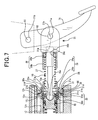
- FIG. 7 is a partially enlarged view of a rear portion of a hydraulic booster of the braking apparatus of FIG. 2 ;
- FIG. 8A is a longitudinal sectional view which illustrates an internal structure of a first solenoid valve installed in the braking apparatus of FIG. 2 ;
- FIG. 8B is a longitudinal sectional view which illustrates an internal structure of a first solenoid valve installed in the braking apparatus of FIG. 2 ;
- FIG. 9 is a flowchart of a collision avoidance control program to be executed by the braking apparatus of FIG. 1 ;
- FIG. 10A is a view which represents a first braking map for use in controlling a braking force in a collision avoidance braking mode
- FIG. 10B is a view which represents a second braking map for use in controlling a braking force in a collision avoidance braking mode
- FIG. 10C is a view which represents a third braking map for use in controlling a braking force in a collision avoidance braking mode
- FIG. 11 is a view which represents a relation between a speed of a vehicle and a braking force in a collision avoidance braking mode of the braking apparatus of FIG. 2 ;
- FIG. 12 is a view which represents a relation among a vehicle equipped with the braking apparatus of FIG. 2 , an obstacle, a detectable range of an obstacle detector, and a collision risk warning location;
- FIG. 13 is an enlarged view of a spool piston and a spool cylinder of a hydraulic booster of the braking apparatus of FIG. 2 in a collision avoidance braking mode;
- FIG. 14 is a partially longitudinal sectional view which illustrates a braking apparatus according to the second embodiment
- FIG. 15A is a view which illustrates a relation between a braking force and a rate of increase in braking force in the braking apparatuses of FIGS. 2 and 14 ;
- FIG. 15B is a view which illustrates a relation between a braking force and a rate of increase in braking force in a frictional brake unit equipped with a pressure regulator and non-linear electromagnetic type first and second solenoid valves.
- FIG. 1 there is shown a brake system (i.e., a braking apparatus) B for vehicles such as automobiles according to an embodiment.
- a brake system i.e., a braking apparatus
- the drawings are merely schematic views which do not necessarily illustrate dimensions of parts of the brake system B precisely.
- the brake system B is engineered as a friction brake unit mounted in a hybrid vehicle.
- the hybrid vehicle is equipped with a hybrid system to drive wheels, for example, front left and right wheels Wfl and Wfr.
- the hybrid vehicle also includes a brake ECU (Electronic Control Unit) 6 , an engine ECU (Electronic Control Unit) 8 , a hybrid ECU (Electronic Control Unit) 9 , a hydraulic booster 10 , a pressure regulator 53 , a hydraulic pressure generator 60 , a brake pedal (i.e., a brake actuating member) 71 , a brake sensor 72 , a first solenoid valve 91 (see FIG. 2 ), and a second solenoid valve 92 (see FIG.
- an obstacle detector 97 an obstacle detector 97 , a warning device 98 , an internal combustion engine 501 , an electric motor 502 , a power pushing member 40 , a split device 503 , a power transmission device 504 , an inverter 506 , and a storage battery 507 .
- the brake system B (i.e., the friction brake unit) is essentially made up of the brake ECU 6 , the hydraulic booster 10 , the pressure regulator 53 , the hydraulic pressure generator 60 , the brake pedal 71 , the brake sensor 72 , the first solenoid valve 91 , the second solenoid valve 92 , the obstacle detector 97 , and the warning device 98 .
- the output power of the engine 501 is transmitted to the driven wheels through the power split device 503 and the power transmission device 504 .
- the output power of the motor 502 is also transmitted to the driven wheels through the power transmission device 504 .
- the inverter 506 works to achieve conversion of voltage between the motor 502 or an electric generator 505 and the battery 507 .
- the engine ECU 8 works to receive instructions from the hybrid ECU 9 to control the power, as outputted from the engine 501 .
- the hybrid ECU 9 serves to control operations of the motor 502 and the generator 505 through the inverter 506 .
- the hybrid ECU 9 is connected to the battery 507 and monitors the state of charge (SOC) of and current charged in the battery 507 .
- SOC state of charge
- a combination of the generator 505 , the inverter 506 , and the battery 507 makes a regenerative braking system A.
- the regenerative braking system A works to make the wheel Wfl and Wfr produce a regenerative braking force as a function of an actually producible regenerative braking force, which will be described later in detail.
- the motor 502 and the generator 505 are illustrated in FIG. 1 as being separate parts, but their operations may be achieved by a single motor/generator.
- Friction braking devices Bfl, Bfr, Brl, and Brr are disposed near the wheels Wfl, Wfr, Wrl, and Wrr of the vehicle.
- the friction braking device Bfl includes a brake disc DRfl and a brake pad (not shown).
- the brake disc DRfl rotates along with the wheel Wfl.
- the brake pad is of a typical type and pressed against the brake disc DRfl to produce a friction braking power.
- the friction braking devices Bfr, Brl, and Brr are made up of brake discs DRfl, DRfr, DRrl, and DRrr and brake pads (not shown), respectively, and identical in operation and structure with the friction braking device Bfl.
- the friction braking devices Bfl, Bfr, Brl, and Brr also include wheel cylinders WCfl, WCfr, WCri, and WCrr, respectively, which are responsive to a master pressure (which is also called master cylinder pressure) that is hydraulic pressure, as developed by the hydraulic booster 10 , required to press the brake pads against the brake discs DRfl, DRfr, DRrl, and DRrr, respectively.
- master pressure which is also called master cylinder pressure
- Wheel speed sensors Sfl, Sfr, Srl, and Srr are disposed adjacent the wheels Wfl, Wfr, Wrl, and Wrr of the vehicle.
- Each of the wheel speed sensors Sfl, Sfr, Srl, and Srr works to output a pulse signal of a frequency as a function of rotational speed of a corresponding one of the wheels Wfl, Wfr, Wrl, and Wrr to the brake ECU 6 .
- the brake sensor 72 measures the amount of stroke, or position of the brake pedal 71 depressed by the vehicle operator or driver and outputs a signal indicative thereof to the brake ECU 6 .
- the brake ECU 6 calculates a braking force, as required by the vehicle driver, as a function of the signal outputted from the brake sensor 72 .
- the brake ECU 6 calculates a target regenerative braking force as a function of the required braking force and outputs a signal indicative of the target regenerative braking force to the hybrid ECU 9 .
- the hybrid ECU 9 calculates the actually producible regenerative braking force as a function of the target regenerative braking force and outputs a signal indicative thereof to the brake ECU 6 .
- the acceleration sensor 96 is connected to the brake ECU 6 .
- the acceleration sensor 96 measures the degree of acceleration of the vehicle and outputs a signal indicative thereof to the brake ECU 6 .
- the obstacle detector 97 is implemented by a stereo camera, a millimeter-wave radar, or an infrared radar to detect an obstacle present ahead of the vehicle.
- the obstacle detector 97 is mounted in front of a driver's seat or a bumper of the vehicle and oriented forward from the vehicle.
- the brake ECU 6 analyzes the output from the obstacle detector 97 to determine whether there is a probability that the vehicle equipped with the brake system B (which will also be referred to as a system vehicle below) will collide with the obstacle or not. Specifically, the brake ECU 6 calculates the speed and acceleration of the system vehicle using outputs from the wheel speed sensors Sfl, Sfr, Srl, and Srr. Next, the brake ECU 6 calculates the distance between the system vehicle and the obstacle using the output from the obstacle detector 97 and also determines the speed and acceleration of the obstacle when it is determined that the obstacle tracked by the obstacle detector 97 is a vehicle preceding the system vehicle.
- the brake ECU 6 calculates the speed and acceleration of the system vehicle relative to the obstacle tracked by the obstacle detector 97 .
- the brake ECU 6 analyzes the distance to the obstacle, the relative speed, and the relative acceleration of the system vehicle to decide whether there is a possibility that the system vehicle will collide with the obstacle or not.
- the warning device 98 is implemented by a speaker, a display, and/or a warning lamp and serves to inform the driver of the vehicle of the risk of collision with an obstacle.
- the hydraulic pressure generator 60 works to produce an accumulator pressure and includes an accumulator 61 , a hydraulic pressure pump 62 , and a pressure sensor 65 .
- the accumulator 61 stores therein brake fluid under pressure. Specifically, the accumulator 61 stores accumulator pressure that is the hydraulic pressure of the brake fluid, as created by the hydraulic pressure pump 62 .
- the accumulator 61 connects with the pressure sensor 65 and the hydraulic pressure pump 62 through a pipe 66 .
- the hydraulic pressure pump 62 connects with a reservoir 19 .
- the hydraulic pressure pump 62 is driven by an electric motor 63 to deliver the brake fluid from the reservoir 19 to the accumulator 61 .
- the pressure sensor 65 works to measure the accumulator pressure that is the pressure in the accumulator 61 .
- the brake ECU 6 outputs a control signal to actuate the motor 63 .
- the hydraulic booster 10 works as a pressure generator to regulate the accumulator pressure, as developed by the hydraulic pressure generator 60 , as a function of the stroke of (i.e., a driver's effort on) the brake pedal 71 to produce a servo pressure which is, in turn, used to generate the master pressure.
- the hydraulic booster 10 includes a master cylinder 11 , a fail-safe cylinder 12 , a first master piston 13 , a second master piston 14 , an input piston 15 , an operating rod 16 , a first return spring 17 , a second return spring 18 , a reservoir 19 , a stopper 21 , a mechanical relief valve 22 , a spool piston 23 , a spool cylinder 24 , a spool spring 25 , a simulator spring 26 , a pedal return spring 27 , a movable member 28 , a first spring retainer 29 , a second spring retainer 30 , a connecting member 31 , a movable member 32 , a retaining piston 33 , a simulator rubber 34 serving as a cushion, a spring retainer 35 , a fail-safe spring 36 , a damper 37 , a first spool spring retainer 38 , a second spring retainer 39 , a pushing member 40 , and sealing members 41 to 49 .
- a part of the hydraulic booster 10 where the first master piston 13 is disposed will be referred to as the front of the hydraulic booster 10
- a part of the hydraulic booster 10 where the operating rod 16 is disposed will be referred to as the rear of the hydraulic booster 10 .
- An axial direction (i.e., a lengthwise direction) of the hydraulic booster 10 thus, represents a front-back direction of the hydraulic booster 10 .
- the master cylinder 11 is of a hollow cylindrical shape which has a bottom 11 a on the front of the hydraulic booster 10 and an opening defining the rear of the hydraulic booster 10 .
- the master cylinder 11 has a given length aligned with the length of the hydraulic booster 10 , a front end (i.e. the bottom 11 a ), and a rear end (i.e., the opening) at the rear of the hydraulic booster 10 .
- the master cylinder 11 also has a cylindrical cavity 11 p extending in the lengthwise or longitudinal direction thereof. The master cylinder 11 is installed in the vehicle.
- the master cylinder 11 has a first port 11 b , a second port 11 c , a third port 11 d , a fourth port 11 e , a fifth port 11 f (i.e., a supply port), a sixth port 11 g , and a seventh port 11 h all of which communicate with the cylindrical cavity 11 p and which are arranged in that order from the front to the rear of the master cylinder 11 .
- the second port 11 c , the fourth port 11 e , the sixth port 11 g , and the seventh port 11 h connect with the reservoir 19 in which the brake fluid is stored.
- the reservoir 19 thus, communicates with the cylindrical cavity 11 p of the master cylinder 11 .
- the sealing members 41 and 42 are disposed in annular grooves formed in an inner peripheral wall of the master cylinder 11 across the second port 11 c .
- the sealing members 41 and 42 are in hermetic contact with an entire outer circumference of the first master piston 13 .
- the sealing members 43 and 44 are disposed in annular grooves formed in the inner peripheral wall of the master cylinder 11 across the fourth port 11 e .
- the sealing members 43 and 44 are in hermetic contact with an entire outer circumference of the second master piston 14 .
- the sealing members 45 and 46 are disposed in annular grooves formed in the inner peripheral wall of the master cylinder 11 across the fifth port 11 f .
- the sealing members 45 and 46 are in hermetic contact with entire outer circumferences of a first cylindrical portion 12 b and a second cylindrical portion 12 c of the fail-safe cylinder 12 , as will be described later in detail.
- the sealing member 47 is disposed in an annular groove formed in the inner peripheral wall of the master cylinder 11 behind the sealing member 46 in hermetic contact with the entire outer circumference of the second cylindrical portion 12 c .
- the sealing members 48 and 49 are disposed in annular grooves formed in the inner peripheral wall of the master cylinder 11 across the seventh port 11 h .
- the sealing members 48 and 49 are in hermetic contact with the entire outer circumference of the second cylindrical portion 12 c of the fail-safe cylinder 12 .
- a support member 59 is disposed on the front surface of the sealing member 45 .
- the sealing member 45 and the support member 59 are installed in a common retaining groove 11 j formed in the inner wall of the master cylinder 11 .
- the sealing member 45 and the support member 59 are, as clearly illustrated in FIG. 3 , placed in abutment contact with each other.
- the support member 59 is of a ring shape and has a slit 59 a formed therein.
- the support member 59 is made of elastic material such as resin and has, as illustrated in FIG. 3 , an inner peripheral surface in contact with the outer circumferential surface of the first cylindrical portion 12 b of the fail-safe cylinder 12 which will be described later in detail.
- the fifth port 11 f works as a supply port which establishes a fluid communication between the outer periphery of the master cylinder 11 and the cylindrical cavity 11 p .
- the fifth port 11 f connects with the accumulator 61 through a pipe 67 defining a flow path.
- the accumulator 61 communicates with the cylindrical cavity 11 p of the master cylinder 11 , so that the accumulator pressure is supplied to the fifth port 11 f.
- the fifth port 11 f and the sixth port 11 g communicate with each other through a connecting fluid path 11 k in which a mechanical relief valve 22 is mounted.
- the mechanical relief valve 22 works to block a flow of the brake fluid from the sixth port 11 g to the fifth port 11 f and allow a flow of the brake fluid from the fifth port 11 f to the sixth port 11 g when the pressure in the fifth port 11 f rises above a given level.
- the first master piston 13 is disposed in a front portion of the cylindrical cavity 11 p of the master cylinder 11 , that is, located behind the bottom 11 a , so that it is slidable in the longitudinal direction of the cylindrical cavity 11 p .
- the first master piston 13 is of a bottomed cylindrical shape and made up of a hollow cylindrical portion 13 a and a cup-shaped retaining portion 13 b extending behind the cylindrical portion 13 a .
- the retaining portion 13 b is fluidically isolated from the cylindrical portion 13 a .
- the cylindrical portion 13 a has fluid holes 13 c formed therein.
- the cylindrical cavity 11 p includes a first master chamber 10 a located in front of the retaining portion 13 b .
- the first master cylinder 10 a is defined by the inner wall of the master cylinder 11 , the cylindrical portion 13 a , and the retaining portion 13 b .
- the first port 11 b communicates with the first master chamber 10 a .
- the first master chamber 10 a is filled with the brake fluid which is supplied to the wheel cylinders WCfl, WCfr, WCrl, and WCrr.
- the first return spring 17 is disposed between the bottom 11 a of the master cylinder 11 and the retaining portion of the first master piston 13 .
- the first return spring 17 urges the first master piston 13 backward to place the first master piston 13 at an initial position, as illustrated in FIG. 2 , unless the brake pedal 71 is depressed by the vehicle driver.
- the second port 11 c coincides or communicates with the fluid holes 13 c , so that the reservoir 19 communicates with the first master chamber 10 a .
- This causes the brake fluid to be delivered from the reservoir 19 to the first master chamber 10 a .
- An excess of the brake fluid in the first master chamber 10 a is returned back to the reservoir 19 .
- the first master piston 13 travels frontward from the initial position, it will cause the second port 11 c to be blocked by the cylindrical portion 13 a , so that the first master chamber 10 a is closed hermetically to create the master pressure therein.
- the second master piston 14 is disposed in a rear portion of the cylindrical cavity 11 p of the master cylinder 11 , that is, located behind the first master piston 13 , so that it is slidable in the longitudinal direction of the cylindrical cavity 11 p .
- the second master piston 14 is made up of a first cylindrical portion 14 a , a second cylindrical portion 14 b lying behind the first cylindrical portion 14 a , and a retaining portion 14 c formed between the first and second cylindrical portions 14 a and 14 b .
- the retaining portion 14 c fluidically isolates the first and second cylindrical portions 14 a and 14 b from each other.
- the first cylindrical portion 14 a has fluid holes 14 d formed therein.
- the cylindrical cavity 11 p includes a second master chamber 10 b located in front of the retaining portion 14 b .
- the second master cylinder 10 b is defined by the inner wall of the master cylinder 11 , the first cylindrical portion 14 a , and the retaining portion 14 c .
- the third port 11 d communicates with the second master chamber 10 b .
- the second master chamber 10 b is filled with the brake fluid which is supplied to the wheel cylinders WCfl, WCfr, WCrl, and WCrr.
- the second master chamber 10 b defines a master chamber within the cylindrical cavity 11 p along with the first master chamber 10 a.
- the second return spring 18 is disposed between the retaining portion 13 of the first master piston 13 and the retaining portion 14 c of the second master piston 14 .
- the second return spring 18 is greater in set load than the first return spring 17 .
- the second return spring 18 urges the second master piston 14 backward to place the second master piston 14 at an initial position, as illustrated in FIG. 2 , unless the brake pedal 71 is depressed by the vehicle driver.
- the fourth port 11 e coincides or communicates with the fluid holes 14 d , so that the reservoir 19 communicates with the second master chamber 10 b .
- This causes the brake fluid to be delivered from the reservoir 19 to the second master chamber 10 b .
- An excess of the brake fluid in the second master chamber 10 b is returned back to the reservoir 19 .
- the second master piston 14 travels frontward from the initial position, it will cause the fourth port 11 e to be blocked by the cylindrical portion 14 a , so that the second master chamber 10 b is closed hermetically to create the master pressure therein.
- the fail-safe cylinder 12 is disposed behind the second master piston 14 within the cylindrical cavity 11 p of the master cylinder 11 to be slidable in the longitudinal direction of the cylindrical cavity 11 p .
- the fail-safe cylinder 12 is made up of the front cylindrical portion 12 a , the first cylindrical portion 12 b , and the second cylindrical portion 12 c which are aligned with each other in the lengthwise direction thereof.
- the front cylindrical portion 12 a , the first cylindrical portion 12 b , and the second cylindrical portion 12 c are formed integrally with each other and all of a hollow cylindrical shape.
- the front cylindrical portion 12 a has an outer diameter a.
- the first cylindrical portion 12 b has an outer diameter b which is greater than the outer diameter a of the front cylindrical portion 12 a .
- the second cylindrical portion 12 c has an outer diameter c which is greater than the outer diameter b of the first cylindrical portion 12 b .
- the fail-safe cylinder 12 has an outer shoulder formed between the front cylindrical portion 12 a and the first cylindrical portion 12 b to define a pressing surface 12 i.
- the second cylindrical portion 12 c has a flange 12 h extending outward from a rear end thereof.
- the flange 12 h contacts with the stopper 21 to stop the fail-safe cylinder 12 from moving outside the master cylinder 11 .
- the second cylindrical portion 12 c has a rear end formed to be greater in inner diameter than another portion thereof to define an inner shoulder 12 j.
- the front cylindrical portion 12 a is disposed inside the second cylindrical portion 14 b of the second master piston 14 .
- the first cylindrical portion 12 b has first inner ports 12 d formed in a rear portion thereof.
- the first inner ports 12 d communicate between the outer peripheral surface and the inner peripheral surface of the first cylindrical portion 12 b , in other words, passes through the thickness of the first cylindrical portion 12 b .
- the second cylindrical portion 12 c has formed in a front portion thereof a second inner port 12 e and a third inner port 12 f which extend through the thickness of the second cylindrical portion 12 c .
- the second cylindrical portion 12 c also has fourth inner ports 12 g formed in a middle portion thereof. The fourth inner ports 12 g extend through the thickness of the second cylindrical portion 12 c and opens toward the front end (i.e., the head) of the input piston 15 disposed within the fail-safe cylinder 12 .
- the second cylindrical portion 12 c as illustrated in FIG. 3 , has a stopper 12 m formed on a front inner peripheral wall thereof.
- the stopper 12 m has formed therein fluid flow paths 12 n extending in the longitudinal direction of the second cylindrical portion 12 c.
- the input piston 15 is, as clearly illustrated in FIG. 2 , located behind the spool cylinder 24 and the spool piston 23 , which will be described later in detail, to be slidable in the longitudinal direction thereof within a rear portion of the second cylindrical portion 12 c of the fail-safe cylinder 12 (i.e., the cylindrical cavity 11 p ).
- the input piston 15 is made of a cylindrical member and substantially circular in cross section thereof.
- the input piston 15 has a rod-retaining chamber 15 a formed in a rear end thereof.
- the rod-retaining chamber 15 a has a conical bottom.
- the input piston 15 also has a spring-retaining chamber 15 b formed in a front end thereof.
- the input piston 15 has an outer shoulder 15 e to have a small-diameter rear portion which is smaller in outer diameter than a major portion thereof.
- the input piston 15 has seal retaining grooves (i.e., recesses) 15 c and 15 d formed in an outer periphery thereof. Sealing members 55 and 56 are disposed in the seal retaining grooves 15 c and 15 d in hermetical contact with an entire inner circumference of the second cylindrical portion 12 c of the fail-safe cylinder 12 .
- the input piston 15 is coupled with the brake pedal 71 through the operating rod 16 and a connecting member 31 , so that the effort acting on the brake pedal 71 is transmitted to the input piston 15 .
- the input piston 15 works to transmit the effort, as exerted thereon, to the spool piston 23 through the simulator spring 26 , the movable member 32 , the simulator rubber 34 , the retaining piston 33 , and the damper 37 , so that the spool piston 23 travels in the longitudinal direction thereof.
- the spring retainer 35 is made up of a hollow cylinder 35 a and a ring-shaped support 35 b extending inwardly from a front edge of the hollow cylinder 35 a .
- the spring retainer 35 is fit in the rear end of the second cylindrical portion 12 c with the support 35 b having the front surface thereof placed in contact with the shoulder 15 e of the input piston 15 .
- the stopper 21 is attached to the inner wall of the rear end of the master cylinder 11 to be movable.
- the stopper 21 is designed as a stopper plate and made up of a ring-shaped base 21 a , a hollow cylinder 21 b , and a stopper ring 21 c .
- the hollow cylinder 21 b extends forward from the front end of the base 21 a .
- the stopper ring 21 c extends inwardly from the front end of the hollow cylinder 21 b.
- the base 21 a has a front surface 21 d which lies inside the hollow cylinder 21 b as a support surface with which the rear end (i.e., the flange 12 h ) of the fail-safe cylinder 12 is placed in contact.
- the flange 12 h will also be referred to as a contact portion below.
- the stopper 21 also includes a ring-shaped retaining recess 21 f formed in the front surface of the base 21 a inside the support surface 21 d in the shape of a groove. Within the retaining recess 21 f , the rear end of the cylinder 35 a of the spring retainer 35 is fit.
- the stopper 21 further includes a ring-shaped protrusion 21 g extending from the front of the base 21 a inside the retaining recess 21 f.
- the base 21 a has a domed recess 21 e formed on a central area of the rear end thereof.
- the recess 21 e serves as a seat and is of an arc or circular shape in cross section.
- the recess 21 e will also be referred to as a seat below.
- the master cylinder 11 has a C-ring 86 fit in a groove formed in the inner wall of the open rear end thereof. The C-ring 86 works as a stopper to hold the stopper 21 from being removed from the master cylinder 11 .
- the movable member 28 is used as a spacer and made of a ring-shaped member.
- the movable member 28 has a front surface which is oriented toward the front of the master cylinder 11 and defines a convex or dome-shaped pressing surface 28 a .
- the pressure surface 28 a is of an arc or circular shape in cross section.
- the pressing surface 28 a is contoured to conform with the shape of the seat 21 e .
- the movable member 28 is disposed on the front end of the first spring retainer 29 which faces the front of the master cylinder 11 .
- the movable member 28 is also arranged behind the stopper 21 with the pressing surface 28 a being placed in slidable contact with the seat 21 e .
- the movable member 28 is movable or slidable on the stopper 21 (i.e., the seat 21 e ).
- the fail-safe spring 36 is disposed between the support 35 b of the spring retainer 35 and the protrusion 21 g of the stopper 21 within the cylinder 35 a of the spring retainer 35 .
- the fail-safe spring 36 is made up of a plurality of diaphragm springs and works to urge the fail-safe cylinder 12 forward against the master cylinder 11 .
- the first spring retainer 29 is made up of a hollow cylinder 29 a and a flange 29 b extending from the front end of the hollow cylinder 29 a inwardly and outwardly.
- the first spring 29 is arranged behind the movable member 28 with the flange 29 b placed in abutment contact with the rear end of the movable member 28 .
- the operating rod 16 has a pressing ball 16 a formed on the front end thereof and a screw 16 b formed on the rear end thereof.
- the operating rod 16 is joined to the rear end of the input piston 15 with the pressing ball 16 a fit in the rod-retaining chamber 15 a .
- the operating rod 16 has a given length extending in the longitudinal direction of the hydraulic booster 10 . Specifically, the operating rod 16 has the length aligned with the length of the hydraulic booster 10 .
- the operating rod 16 passes through the movable member 28 and the first spring retainer 29 .
- the second spring retainer 30 is disposed behind the first spring retainer 29 in alignment therewith and secured to the rear portion of the operating rod 16 .
- the second spring retainer 30 is of a hollow cylindrical shape and made up of an annular bottom 30 a and a cylinder 30 b extending from the bottom 30 a frontward.
- the bottom 30 a has a threaded hole 30 c into which the screw 16 b of the operating rod 16 is fastened.
- the pedal return spring 27 is disposed between the flange 29 b of the first spring retainer 29 and the bottom 30 a of the second spring retainer 30 .
- the pedal return spring 27 is held inside the cylinder 29 a of the first spring retainer 29 and the cylinder 30 b of the second spring retainer 30 .
- the connecting member 31 has a threaded hole 31 a formed in the front end thereof.
- the screw 16 b of the operating rod 16 is fastened into the threaded hole 31 a to join the connecting member 31 to the rear end of the operating rod 16 .
- the bottom 30 a of the second spring retainer 30 is in contact with the front end of the connecting member 31 .
- the connecting member 31 has an axial through hole 31 b formed in substantially the center thereof in the longitudinal direction of the hydraulic booster 10 .
- the threaded hole 30 c of the second spring retainer 30 and the threaded hole 31 a of the connecting member 31 are in engagement with the screw 16 b of the operating rod 16 , thereby enabling the connecting member 31 to be regulated in position thereof relative to the operating rod 16 in the longitudinal direction of the operating rod 16 .
- the brake pedal 71 works as a brake actuating member and is made of a lever on which an effort is exerted by the driver of the vehicle.
- the brake pedal 71 has an axial hole 71 a formed in the center thereof and a mount hole 71 b formed in an upper portion thereof.
- a bolt 81 is inserted into the mount hole 71 b to secure the brake pedal 71 to a mount base of the vehicle, as indicated by a broken line in FIG. 2 .
- the brake pedal 71 is swingable about the bolt 81 .
- a connecting pin 82 is inserted into the axial hole 71 a of the brake pedal 71 and the axial hole 31 b of the connecting member 31 , so that the swinging motion of the brake pedal 71 is converted into linear motion of the connecting member 31 .
- the pedal return spring 27 urges the second spring retainer 30 and the connecting member 31 backward to keep the brake pedal at the initial position, as illustrated in FIG. 2 .
- the depression of the brake pedal 71 will cause the brake pedal 71 to swing about the mount hole 71 b (i.e., the bolt 81 ) and also cause the axial holes 71 a and 31 b to swing about the mount hole 71 b .
- a two-dot chain line in FIG. 2 indicates a path of travel of the axial holes 71 a and 31 b .
- the axial holes 71 a and 31 b move upward along the two-dot chain line. This movement causes the movable member 28 and the first spring retainer 29 to swing or slide on the stopper 21 to prevent an excessive pressure (i.e., shearing force) from acting on the pedal return spring 27 .
- the retaining piston 33 is, as clearly illustrated in FIG. 2 , disposed inside the front portion of the second cylindrical portion 12 c of the fail-safe cylinder 12 (i.e., within the cylindrical cavity 11 p of the master cylinder 11 ) to be slidable in the longitudinal direction thereof.
- the retaining piston 33 is made of a bottomed cylindrical member and includes a front end defining a bottom 33 a and a cylinder 33 b extending rearward from the bottom 33 a
- the bottom 33 a has formed in the front end thereof a concave recess 33 c serving as a retaining cavity.
- the cylinder 33 b has a seal-retaining groove 33 d formed in the outer circumference thereof.
- a seal 75 is fit in the seal-retaining groove 33 d in contact with an entire inner circumference of the second cylindrical portion 12 c of the fail-safe cylinder 12 .
- a C-ring 85 is, as clearly illustrated in FIG. 2 , fit in an angular groove formed in the outer periphery of the second cylindrical portion 12 c .
- the C-ring 85 is contactable with the rear end of the retaining position 33 , that is, works as a stopper to hold the retaining piston 33 from sliding backward.
- the movable member 32 is, as illustrated in FIG. 2 , disposed inside the rear portion of the second cylindrical portion 12 c of the fail-safe cylinder 12 (i.e., within the cylindrical cavity 11 p of the master cylinder 11 ) to be slidable in the longitudinal direction thereof.
- the movable member 32 is made up of a flange 32 a formed on the front end thereof and a shaft 32 b extending backward from the flange 32 a in the longitudinal direction of the hydraulic booster 10 .
- the flange 32 a has a rubber-retaining chamber 32 c formed in the front end thereof in the shape of a concave recess.
- the cylindrical simulator rubber 34 is fit which protrudes outside the front end of the rubber-retaining chamber 32 c .
- the simulator rubber i.e., the movable member 32
- the retaining piston 33 When placed at an initial position, as illustrated in FIG. 2 , the simulator rubber (i.e., the movable member 32 ) is located away from the retaining piston 33 .
- the flange 32 a has formed therein a fluid path 32 h which communicates between a fluid chamber formed in front of the movable member 32 , in other words, between the front end of the flange 32 a and the inner wall of the retaining piston 33 , and a simulator chamber 10 f , which will be described later in detail.
- a fluid path 32 h which communicates between a fluid chamber formed in front of the movable member 32 , in other words, between the front end of the flange 32 a and the inner wall of the retaining piston 33 , and a simulator chamber 10 f , which will be described later in detail.
- the simulator chamber 10 f (which will also be referred to as a stroke chamber below) is defined by the inner wall of the second cylindrical portion 12 c of the fail-safe cylinder 12 , the rear end of the retaining piston 33 , and the front end of the input piston 15 .
- the simulator chamber 10 f is filled with the brake fluid and works as a brake simulator chamber to develop a reactive pressure in response to the braking effort on the brake pedal 71 .
- the simulator spring 26 is a braking simulator member engineered as a braking operation simulator and disposed between the flange 32 a of the movable member 32 and the spring-retaining chamber 15 b of the input piston 15 within the simulator chamber 10 f .
- the simulator spring 26 is located ahead of the input piston 15 within the second cylindrical portion 12 c of the fail-safe cylinder 12 (i.e., the cylindrical cavity 11 p of the master cylinder 11 ).
- the shaft 32 b of the movable member 32 is inserted into the simulator spring 26 to retain the simulator spring 26 .
- the simulator spring 26 has a front portion press-fit on the shaft 32 b of the movable member 32 .
- the first inner ports 12 d open at the outer periphery of the first cylindrical portion 12 b of the fail-safe cylinder 12 .
- the second cylindrical portion 12 c is, as described above, shaped to have the outer diameter c greater than the outer diameter b of the first cylindrical portion 12 b .
- the exertion of the accumulator pressure on the fifth port 11 f i.e., when the brake fluid is being supplied from the accumulator 61 to the fifth port 11 f
- the accumulator pressure i.e., the pressure of the brake fluid delivered from the accumulator 61
- a difference in traverse cross-section between the first cylindrical portion 12 b and the second cylindrical portion 12 c to press the fail-safe cylinder 12 rearward against the stopper 21 , thereby placing the fail-safe cylinder 12 at a rearmost position (i.e., the initial position) of the above describe preselected allowable range.
- the fourth inner ports 12 g communicate with the seventh port 11 h of the master cylinder 11 .
- the hydraulic communication between the simulator chamber 10 f and the reservoir 19 is established by a reservoir flow path, as defined by the fourth inner ports 12 g and the seventh port 11 h .
- the simulator chamber 10 f is a portion of the cylindrical cavity 11 p , as defined ahead the input piston 15 inside the fail-safe cylinder 12 .
- a change in volume of the simulator chamber 10 f arising from the longitudinal sliding movement of the input piston 15 causes the brake fluid within the simulator chamber 10 f to be returned back to the reservoir 19 or the brake fluid to be supplied from the reservoir 19 to the simulator chamber 10 f , thereby allowing the input piston 15 to move frontward or backward in the longitudinal direction thereof without undergoing any hydraulic resistance.
- the spool cylinder 24 is, as illustrated in FIG. 3 , fixed in the first cylindrical portion 12 b of the fail-safe cylinder 12 (i.e., the cylindrical cavity 11 p of the master cylinder 11 ) behind the second master piston 14 .
- the spool cylinder 24 is of a substantially hollow cylindrical shape.
- the spool cylinder 24 has seal-retaining grooves 24 a and 24 b formed in an outer periphery thereof in the shape of a concave recess. Sealing members 57 and 58 are fit in the seal-retaining grooves 24 a and 24 b in direct contact with an entire circumference of the inner wall of the first cylindrical portion 12 b to create a hermetical seal therebetween.
- the sealing members 57 and 58 develop mechanical friction between themselves and the inner wall of the first cylindrical portion 12 b to hold the spool cylinder 24 from advancing in the first cylindrical portion 12 b .
- the spool cylinder 24 has the rear end placed in contact with the stopper 12 m , so that it is held from moving backward.
- the spool cylinder 24 has formed therein a spool port 24 c which communicates between inside and outside thereof.
- the spool port 24 c communicates with the first inner ports 12 d .
- the spool cylinder 24 has a first spool groove 24 d formed in a portion of an inner wall thereof which is located behind the spool port 24 c .
- the first spool groove 24 d extends along an entire inner circumference of the spool cylinder 24 in the shape of a concave recess.
- the spool cylinder 24 also has a second spool groove 24 f formed in a rear end of the inner wall thereof which is located behind the first spool groove 24 d .
- the second spool groove 24 f extends along the entire inner circumference of the spool cylinder 24 in the shape of a concave recess.
- the spool cylinder 24 also has a fluid flow groove 24 e formed in a portion of an outer wall thereof which is located behind the seal-retaining groove 24 b .
- the fluid flow groove 24 e extends along an entire outer circumference of the spool cylinder 24 in the shape of a concave recess.
- the third inner port 12 f opens into the fluid flow groove 24 e .
- the fluid flow groove 24 e defines a flow path leading to the reservoir 19 through the third inner port 12 f and the sixth port 11 g.
- the spool piston 23 is made of a cylindrical shaft which is of a circular cross section.
- the spool piston 23 is disposed inside the spool cylinder 24 to be slidable in the longitudinal direction thereof.
- the spool piston 23 has a cylindrical rear end defining an in-cylinder portion 23 a which is slidable in the longitudinal direction thereof into and out of the retaining cavity 33 c of the retaining piston 33 .
- the outer periphery of the in-cylinder portion 23 a of the spool piston 23 is separate from the inner periphery of the retaining cavity 33 c of the retaining piston 33 through an air gap to define a pilot-pressure induction path 23 x.
- the damper 37 is installed between the bottom of the retaining cavity 33 c and the rear end of the spool piston 23 .
- the damper 37 is made of a cylindrical elastic rubber, but may alternatively be implemented by an elastically deformable member such as a coil spring or a diaphragm.
- the spool piston 23 has a third spool groove 23 b formed in an axial central portion of an outer wall thereof.
- the third spool groove 23 b extends along an entire outer circumference of the spool piston 23 in the shape of a concave recess.
- the spool piston 23 also has a fourth spool groove 23 c formed in a portion of the outer wall thereof which is located behind the third spool groove 23 b .
- the fourth spool groove 23 c extends along the entire outer circumference of the spool piston 23 in the shape of a concave recess.
- the spool piston 23 also has an elongated fluid flow hole 23 e which extends along the longitudinal center line thereof from the front end behind the middle of the length of the spool piston 23 .
- the spool piston 23 also has formed therein a first fluid flow port 23 d and a second fluid flow port 23 f which communicate between the fourth spool groove 23 c and the fluid flow hole 23 e.
- the hydraulic booster 10 also includes a servo chamber 10 c which is defined by the rear inner wall of the second master piston 14 , the front end portion of the spool piston 23 , and the front end of the spool cylinder 24 behind the retaining portion 14 c of the second master piston 14 within the cylindrical cavity 11 p of the master cylinder 11 .
- the first spool spring retainer 38 is, as clearly illustrated in FIG. 2 , made up of a retaining disc 38 a and a cylindrical fastener 38 b .
- the retaining disc 38 a is fit in an inner front end wall of the front cylindrical portion 12 a of the fail-safe cylinder 12 and closes a front opening of the front cylindrical portion 12 a .
- the cylindrical fastener 38 b extends frontward from the front center of the retaining disc 38 a .
- the cylindrical fastener 38 b has an internal thread formed in an inner periphery thereof.
- the retaining disc 38 a has a contact portion 38 c formed on a central area of the rear end thereof.
- the retaining disc 38 a also has fluid flow holes 38 d passing through the thickness thereof.
- the pushing member 40 is made of a rod and has a rear end engaging the internal thread of the cylindrical fastener 38 b.
- the second spool spring retainer 39 is, as illustrated in FIG. 3 , made up of a hollow cylindrical body 39 a and a ring-shaped retaining flange 39 b
- the cylindrical body 39 a has a front end defining a bottom 39 c .
- the retaining flange 39 b extends radially from the rear end of the cylindrical body 39 a .
- the front end of the spool piston 23 is fit in the cylindrical body 39 a in engagement with an inner periphery of the cylindrical body 39 a , so that the second spool spring retainer 39 is secured to the front end of the spool piston 23 .
- the bottom 39 c has a through hole 39 d formed therein.
- the second spool spring retainer 39 is, as can be seen from FIG. 2 , aligned with the first spool spring retainer 38 at a given interval away from the contact portion 38 c.
- the spool spring 25 is, as illustrated in FIGS. 2 and 3 , disposed between the retaining disc 38 a of the first spool spring retainer 38 and the retaining flange 39 b of the second spool spring retainer 39 .
- the spool spring 25 works to urge the spool piston 23 backward relative to the fail-safe cylinder 12 (i.e., the master cylinder 11 ) and the spool cylinder 24 .
- the spring constant of the simulator spring 26 is set greater than that of the spool spring 25 .
- the spring constant of the simulator spring 26 is also set greater than that of the pedal return spring 27 .
- the simulator made up of the simulator spring 26 , the pedal return spring 27 , and the simulator rubber 34 will be described below.
- the simulator is a mechanism engineered to apply a reaction force to the brake pedal 71 to imitate an operation of a typical brake system, that is, make the driver of the vehicle experience the sense of depression of the brake pedal 71 .
- reaction pressure (which will also be referred to as a reactive force) acting on the brake pedal 71 .
- the reaction pressure is given by the sum of a set load of the pedal return spring 27 and a product of the spring constant of the pedal return spring 27 and the stroke of the brake pedal 71 (i.e., the connecting member 31 ).
- the simulator rubber 34 When the simulator rubber 34 contacts the retaining piston 33 , and the brake pedal 71 is further depressed, it usually causes the simulator rubber 34 to contract.
- the simulator rubber 34 has a spring constant which increases, in the nature thereof, as the simulator rubber 34 contracts. Therefore, there is a transient time for which the reaction pressure exerted on the brake pedal 71 changes gently to minimize the driver's discomfort arising from a sudden change in reaction pressure exerted on the foot of the driver of the vehicle.
- the simulator rubber 34 serves as a cushion to decrease the rate of change in reaction pressure acting on the brake pedal 71 during the depression thereof.
- the simulator rubber 34 of this embodiment is, as described above, secured to the movable member 32 , but may be merely placed between opposed end surfaces of the movable member 32 and the retaining piston 33 .
- the simulator rubber 34 may alternatively be attached to the rear end of the retaining piston 33 .
- the reaction pressure exerted on the brake pedal 71 during the depression thereof increases at a smaller rate until the simulator rubber 34 contacts the retaining piston and then increases at a greater rate, thereby giving a typical sense of operation (i.e., depression) of the brake pedal 71 to the driver of the vehicle.
- the pressure regulator 53 works to increase or decrease the master pressure that is the pressure of brake fluid delivered from the master chambers 10 a and 10 b to produce wheel cylinder pressure to be fed to the wheel cylinders WCfl, WCfr, WCrl, and WCrr and is engineered to achieve known anti-lock braking control or known electronic stability control to avoid lateral skid of the vehicle.
- the pressure regulator 53 may be designed to have a known structure such as taught in Japanese Patent First Publication No. 2013-6534 or No. 2008-87069, and explanation thereof in detail will be omitted here.
- the wheel cylinders WCfr and WCfl are connected to the first port 11 b of the first master cylinder 10 a through the pipe 52 and the pressure regulator 53 .
- the wheel cylinders WCrr and WCrl are connected to the third port 11 d of the second master cylinder 10 b through the pipe 51 and the pressure regulator 53 .
- the operation of the hydraulic booster 10 will be described below in detail.
- the hydraulic booster 10 is equipped with a spool valve made up of the spool cylinder 24 and the spool piston 23 .
- the spool valve is driven or slides in the longitudinal direction of the master cylinder 11 in response to the driver's effort on the brake pedal 71 .
- the hydraulic booster 10 then enters any one of the pressure-reducing mode, the pressure-increasing mode, and the pressure-holding mode.
- the pressure-reducing mode is entered when the brake pedal 71 is not depressed or the driver's effort (which will also be referred to as braking effort below) on the brake pedal 71 is lower than or equal to a frictional braking force generating level P 2 , as indicated in a graph of FIG. 4 .
- the simulator rubber 34 i.e., the movable member 32
- the bottom 33 a of the retaining piston 33 is separate from the bottom 33 a of the retaining piston 33 .
- the spool piston 23 When the simulator rubber 34 is located away from the bottom 33 a of the retaining piston 33 , the spool piston 23 is placed by the spool spring 25 at the rearmost position in the movable range thereof (which will also be referred to as a pressure-reducing position below).
- the spool port 24 c is, as illustrated in FIG. 3 , blocked by the outer periphery of the spool piston 23 , so that the accumulator pressure that is the pressure in the accumulator 61 is not exerted on the servo chamber 10 c.
- the fourth spool groove 23 c of the spool piston 23 communicates with the second spool groove 24 f of the spool cylinder 24 .
- the servo chamber 10 c therefore, communicates with the reservoir 19 through a pressure-reducing flow path, as defined by the fluid flow hole 23 e , the first fluid flow part 23 d , the fourth spool groove 23 c , the second spool groove 24 f , the fluid flow path 12 n , the fluid flow groove 24 e , the third inner port 12 f , and the sixth port 11 g .
- the hydraulic booster 10 When the load or effort applied to the brake pedal 71 is lower than or equal to the frictional braking force generating level P 2 , the hydraulic booster 10 is kept from entering the pressure-increasing mode, so that the servo pressure and the master pressure are not developed, thus resulting in no frictional braking force generated in the friction braking devices Bfl, Bfr, Brl, and Brr.
- the hydraulic booster 10 enters the pressure-increasing mode. Specifically, the application of effort to the brake pedal 71 causes the simulator rubber 34 (i.e., the movable member 32 ) to push the retaining piston 33 to urge the spool piston 23 forward. The spool piston 23 then advances to a front position, as illustrated in FIG. 5 within the movable range against the pressure, as produced by the spool spring 25 . Such a front position will also be referred to as a pressure-increasing position below.
- the first fluid flow port 23 d is closed by the inner periphery of the spool cylinder 24 to block the communication between the first fluid flow part 23 d and the second spool groove 24 f . This blocks the fluid communication between the servo chamber 10 c and the reservoir 19 .
- the spool port 24 c communicates with the third spool groove 23 b .
- the third spool groove 23 b , the first spool groove 24 d , and the fourth spool groove 23 c communicate with each other, so that the pressure in the accumulator 61 (i.e., the accumulator pressure) is delivered to the servo chamber 10 c through a pressure-increasing flow path, as defined by the first inner port 12 d , the spool port 24 c , the third spool groove 23 b , the first spool groove 24 d , the fourth spool groove 23 c , the second fluid flow port 23 f , the fluid flow hole 23 e , and the connecting hole 39 d .
- the rise in servo pressure will cause the second master piston 14 to move forward, thereby moving the first master piston 13 forward through the second return spring 18 . This results in generation of the master pressure within the second master chamber 10 b and the first master chamber 10 a .
- the master pressure increases with the rise in servo pressure.
- the diameter of the front and rear seals (i.e., the sealing members 43 and 44 ) of the second master piston 14 is identical with that of the front and rear seals (i.e., the sealing members 41 and 42 ) of the first master piston 13 , so that the servo pressure will be equal to the master pressure, as created in the second master chamber 10 b and the first master chamber 10 a.
- the generation of the master pressure in the second master chamber 10 b and the first master chamber 10 a will cause the brake fluid to be delivered from the second master chamber 10 b and the first master chamber 10 a to the wheel cylinders WCfr, WCfl, WCrr, and WCrl through the pipes 51 and 52 and the pressure regulator 53 , thereby elevating the pressure in the wheel cylinders WCfr, WCfl, WCrr, and WCrl (i.e., the wheel cylinder pressure) to produce the frictional braking force applied to the wheels Wfr, Wfl, Wrr, and Wrl.
- the accumulator pressure is applied to the servo chamber 10 c , so that the servo pressure rises.
- This causes a return pressure that is given by the product of the servo pressure and a cross-sectional area of the spool piston 23 (i.e., a seal area) to act on the pool piston 23 backward.
- the sum of the return pressure and the pressure, as produced by the spool spring 25 and exerted on the spool piston 23 exceeds the input pressure exerted on the spool piston 23 , the spool piston 23 is moved backward and placed in a pressure-holding position, as illustrated in FIG. 6 , that is intermediate between the pressure-reducing position and the pressure-increasing position.
- the spool port 24 c is closed by the outer periphery of the spool piston 23 .
- the fourth spool groove 23 c is also closed by the inner periphery of the spool cylinder 24 . This blocks the communication between the spool port 24 c and the second fluid flow port 23 f to block the communication between the servo chamber 10 c and the accumulator 61 , so that the accumulator pressure is not applied to the servo chamber 10 c.
- the fourth spool groove 23 c is closed by the inner periphery of the spool cylinder 24 , thereby blocking the communication between the first fluid flow port 23 d and the second spool groove 24 f to block the communication between the servo chamber 10 c and the reservoir 19 , so that the servo chamber 10 c is closed completely.
- This causes the servo pressure, as developed upon a change from the pressure-increasing mode to the pressure-holding mode, to be kept as it is.
- the pressure-holding mode is maintained.
- the effort on the brake pedal 71 drops, so that the input pressure applied to the spool piston 23 decreases, and the sum of the return pressure applied to the spool piston 23 and the pressure, as produced by the spool spring 25 and exerted on the spool piston 23 , exceeds the input pressure exerted on the spool piston 23 , it will cause the spool piston 23 to be moved backward and placed in the pressure-reducing position, as illustrated in FIG. 3 .
- the pressure-reducing mode is then entered, so that the servo pressure in the servo chamber 10 c drops.
- the friction between the outer periphery of the spool piston 23 and the inner periphery of the spool cylinder 24 results in hysteresis in the movement of the spool piston 23 , which disturbs the movement of the spool piston 23 in the longitudinal direction thereof, thus leading to less frequent switching from the pressure-holding mode to either of the pressure-reducing mode or the pressure-increasing mode.
- the relation between the regenerative braking force and the frictional braking force will be described below with reference to FIG. 4 .
- the hydraulic booster 10 is kept in the pressure-reducing mode without switching to the pressure-increasing mode, so that the frictional braking force is not developed.
- the brake system B as illustrated in FIG. 4 , has a regenerative braking force generating level P 1 indicative of the braking effort applied to the brake pedal 71 which is set lower than the frictional braking force generating level P 2 .
- the brake system B is equipped with the brake sensor 72 .
- the brake sensor 72 works to measure an amount of stroke of the brake pedal 71 .
- the driver's effort i.e. the braking effort
- the brake ECU 6 determines whether the braking effort has exceeded the regenerative braking force generating level P 1 or not using the output from the brake sensor 72 .
- the brake ECU 6 calculates the target regenerative braking force as a function of the output from the brake sensor 72 and outputs a signal indicative thereof to the hybrid ECU 9 .
- the hybrid ECU 9 uses the speed V of the vehicle, the state of charge in the battery 507 , and the target regenerative braking force to compute the actually producible regenerative braking force that is a regenerative braking force the regenerative braking system A is capable of producing actually.
- the hybrid ECU 9 then controls the operation of the regenerative braking system A to create the actually producible regenerative braking force.
- the hybrid ECU 9 When determining that the actually producible regenerative braking force does not reach the target regenerative braking force, the hybrid ECU 9 subtracts the actually producible regenerative force from the target regenerative braking force to derive an additional frictional braking force.
- the event that the actually producible regenerative braking force does not reach the target regenerative braking force is usually encountered when the speed V of the vehicle is lower than a given value or the battery 507 is charged fully or near fully.
- the hybrid ECU 9 outputs a signal indicative of the additional frictional braking force to the brake ECU 6 .
- the brake ECU 6 Upon reception of the signal from the hybrid ECU 9 , the brake ECU 6 controls the operation of the pressure regulator 53 to control the wheel cylinder pressure to make the friction braking devices Bfl, Bfr, Brl, and Brr create the additional regenerative braking force additionally. Specifically, when it is determined that the actually producible regenerative braking force is less than the target regenerative braking force, the brake ECU 6 actuates the pressure regulator 53 to develop the additional regenerative braking force in the friction braking devices Bfl, Bfr, Brl, and Brr to compensate for a difference (i.e., shortfall) between the target regenerative braking force and the actually producible regenerative braking force, thereby achieving the target regenerative braking force.
- a difference i.e., shortfall
- the pressure regulator 53 regulates the pressure to be developed in the wheel cylinders WCfl, WCfr, WCrl, and WCrr to produce a degree of frictional braking force through the friction braking devices Bfl, Bfr, Brl, and Brr which is equivalent to a shortfall in the regenerative braking force.
- the fail-safe spring 36 urges or moves the fail-safe cylinder 12 forward until the flange 12 h of the fail-safe cylinder 12 hits the stopper ring 21 c of the stopper 21 .
- the second cylindrical portion 12 c of the fail-safe cylinder 12 then blocks the seventh port 11 h of the master cylinder 11 to close the simulator chamber 10 f liquid-tightly.
- the braking effort on the brake pedal 71 is transmitted to the fail-safe cylinder 12 through the stopper 12 m , so that the fail-safe cylinder 12 advances.
- This causes the pushing member 40 to contact the retaining portion 14 c of the second master piston 14 or the pressing surface 12 i of the fail-safe cylinder 12 to contact the rear end of the second cylindrical portion 14 b of the second master piston 14 , so that the braking effort on the brake pedal 71 is inputted to the second master piston 14 .
- the fail-safe cylinder 12 pushes the second master piston 14 .
- the fail-safe cylinder 12 advances, so that the second cylindrical portion 12 c which has the outer diameter c greater than the outer diameter b of the first cylindrical portion 12 b passes through the sealing member 45 .
- the master cylinder 11 is designed to have the inner diameter greater than the outer diameter c of the second cylindrical portion 12 c for allowing the second cylindrical portion 12 c to move forward. Consequently, when the hydraulic pressure generator 60 is operating properly, the outer periphery of the first cylindrical portion 12 b is, as can be seen in FIG. 2 , separated from the inner periphery of the master cylinder 11 through an air gap.
- the entire circumferential area of the front end of the sealing member 45 is, as clearly illustrated in FIG. 3 , in direct contact with the support member 59 .
- the inner peripheral surface of the support member 59 is in direct contact with the outer peripheral surface of the first cylindrical portion 12 b of the fail-safe cylinder 12 .
- the sealing member 45 is firmly held at the front end thereof by the support member 59 without any air gap therebetween, thus avoiding damage to the sealing member 45 when the fail-safe cylinder 12 moves forward in the event of malfunction of the hydraulic pressure generator 60 , so that the first cylindrical portion 12 b slides on the sealing member 45 .
- the support member 59 has, as described above, the slit formed therein.
- the slit makes the support member 59 expand outwardly upon the forward movement of the fail-safe cylinder 12 , thereby allowing the second cylindrical portion 12 c to pass through the support member 59 .
- the sealing member 45 is, as described above, held at the front end thereof by the support member 59 , thus avoiding damage to the sealing member 45 upon the passing of the second cylindrical portion 12 c through the support member 59 .
- the mechanical relief valve 22 will be opened, so that the brake fluid flows from the fifth port 11 f to the sixth port 11 g and to the reservoir 19 . This avoids damage to the pipe 67 and the hydraulic booster 10 .
- the fluid flow path 12 n and the second inner port 12 e are fluidly connected through a flow path 12 y formed between the outer periphery of the spool cylinder 24 and the inner periphery of the fail-safe cylinder 12 .
- the pilot chamber 12 x communicates with the sixth port 11 g through the fluid flow path 12 n , the flow path 12 y , and the second inner port 12 e.
- the master cylinder 11 as illustrated in FIG. 2 , has a hydraulic pressure supply port 11 z leading to the sixth port 11 g .
- the hydraulic pressure supply port 11 z also connects with the pipe 67 through the pipe 68 .
- the first solenoid valve 91 is disposed in the pipe 68 .
- the pilot chamber 12 x connects with the accumulator 61 through the first solenoid valve 91 .
- the first solenoid valve 91 is of a normally-closed type. Specifically, when deenergized, the first solenoid valve 91 keeps the pipe 68 closed. Alternatively, when energized, the first solenoid valve 91 opens the pipe 68 .
- the first solenoid valve 91 is controlled in operation by the brake ECU 6 and works to adjust the accumulator pressure to a pilot pressure.
- the second solenoid valve 92 is disposed in a flow path 95 connecting between the pilot chamber 12 x and the reservoir 19 .
- the second solenoid valve 92 is of a normally-open type and, when deenergized, keeps the flow path 95 opened.
- the first solenoid valve 91 and the second solenoid valve 92 are each implemented by a linear electromagnetic valve which is capable of regulating a flow rate of brake fluid passing therethrough or regulating the hydraulic pressure of brake fluid flowing upstream thereof.
- the first solenoid valve 91 consists essentially of a valve body 91 a , a plunger 91 b , a coil spring 91 c , a coil 91 d , and a core 91 i .
- the valve body 91 a is made of non-magnetic material and has an inlet 91 j and an outlet 91 k leading to the inlet 91 j through a fluid path formed therein.
- the inlet 91 j is formed in an end of the valve body 91 a .
- the outlet 91 k is formed in a side wall of the valve body 91 a .
- the valve body 91 a has a tapered or conical valve seat 91 e formed on an inner wall thereof.
- the conical valve seat 91 e is located inside the inlet 91 j .
- the plunger 91 b consists of a spherical or conical valve body 91 f , an armature 91 g , and a bar 91 h connecting the valve body 91 f and the armature 91 g .
- the armature 91 g is formed by a magnetic block made of, for example, an electromagnetic stainless steel.
- the plunger 91 b is disposed inside the valve body 91 a to be slidable to bring the valve body 91 f into hermetic contact with the valve seat 91 e.
- the coil 19 d is installed in the valve body 91 a and located outside the periphery of the armature 91 g .
- the core 91 i is installed away from the inlet 91 j within the valve body 91 a and faces the armature 91 g .
- the core 91 i is made of magnetic material such as electromagnetic stainless steel.
- the coil spring 91 c is installed in the valve body 91 a and works as a biasing mechanism to urge the plunger 91 b into constant contact with the valve seat 91 e , thereby closing the fluid path in the valve body 91 a , that is, blocking the fluid communication between the inlet 91 j and the outlet 91 k.
- the coil 91 d When the coil 91 d is energized, it will produce a magnetic attraction to pull the armature 91 g to the core 91 i , so that the pressure pressing the plunger 91 b against the valve seat 91 e will be decreased, thus causing the fluid path in the valve body 91 a to be opened by the pressure of the brake fluid entering the inlet 91 j .
- the brake fluid therefore, stars to flow from the inlet 91 j to the outlet 91 k of the first solenoid valve 91 .
- the plunger 91 b is moved to a place where a difference in pressure between the inlet 91 j and the outlet 91 k which acts on the plunger 91 b is in balance with the pressure which is produced by the coil 91 d and the coil spring 91 c and exerted on the plunger 91 b (i.e. the sum of the magnetic attraction and the spring pressure).
- the amount of electric current supplied to the coil 91 d is regulated in a duty-factor control mode. Specifically, the pressure which presses the valve body 91 f against the valve seat 91 e depends upon a duty factor of a pulse signal produced by the brake ECU 6 , thereby changing the difference in pressure between the inlet 91 j and the outlet 91 k.
- the second solenoid valve 92 as illustrated in FIG. 8B , consists essentially of a valve body 92 a , a plunger 92 b , a coil spring 92 c , a coil 92 d , and a core 92 i .
- the valve body 92 a , the plunger 92 b , the coil spring 92 c , the coil 92 d , and the core 92 i are substantially identical in structure or operation with the valve body 91 a , the plunger 91 b , the coil spring 91 c , the coil 91 d , and the core 91 i of the first solenoid valve 91 , and explanation thereof in detail will be omitted here.
- the coil spring 92 c is, as can be seen in FIG. 8B , disposed so as to urge the plunger 92 b away from the valve seat 92 e .
- the core 92 i is installed close to the inlet 92 j within the valve body 92 a and faces the armature 92 g .
- the coil spring 92 c works to keep the valve body 92 f away from the valve seat 92 e , thereby opening the fluid path connecting the inlet 92 i and the outlet 92 k in the valve body 92 a .
- the second solenoid vale 92 is an electromagnetic relief valve working to control the pressure of brake fluid to be relieved therefrom as a function of an amount of electric current supplied to the coil 92 d.
- the ECU 6 closes the second solenoid valve 92 , thereby hermetically closing the pilot chamber 12 x which leads to the reservoir 19 , that is, blocking the fluid communication between the pilot chamber 12 x and the reservoir 19 . Subsequently, the ECU 6 opens the first solenoid valve 91 , so that the brake fluid whose pressure is adjusted by the first solenoid valve 91 to the pilot pressure, as clearly illustrated in FIG. 13 , flows into the pilot chamber 12 x through the hydraulic pressure supply port 11 z , the sixth port 11 g , the second inner port 12 e , the flow path 12 y , and the fluid flow path 12 n .
- the brake fluid as adjusted to the pilot pressure, then flows to the pilot-pressure induction path 23 x and to the retaining cavity 33 c of the retaining piston 33 .
- the pilot pressure then acts on the rear end surface of the in-cylinder portion 23 a of the spool piston 23 .
- This causes a drive force (i.e., a hydraulic pressure), created by the product of the pilot pressure and a transverse sectional area (i.e., a sealing area) of the spool piston 23 , to be exerted on the spool piston 23 , so that the spool piston 23 moves forward to achieve the pressure-increasing mode, as described already, thereby developing the servo pressure in the servo chamber 10 c.
- the pilot pressure When the pilot pressure is admitted into the pilot chamber 12 x , it urges the pressure-holding piston 33 , as clearly illustrated in FIG. 13 , backward until it contacts with the C-ring 85 .
- the C-ring 85 works as a stopper to hold the retaining piston 33 from sliding backward, thereby eliminating a change in sense of depression of the brake pedal 71 , as resulting from the backward movement of the pressure-holding piston 33 , which the driver of the vehicle feels.
- the pressure sensor 99 is disposed in the pipe 68 between the first solenoid valve 91 and the hydraulic pressure supply port 11 g and works to measure the pressure of the brake fluid in the pipe 68 , i.e., the pilot pressure inducted into the pilot chamber 12 x and output a signal indicative thereof to the ECU 6 .
- the collision avoidance braking task to be executed by the brake ECU 6 to achieve the collision braking mode will be described below with reference to a flowchart of FIG. 9 .
- the brake ECU 6 works as a collision avoidance controller. When the system vehicle is enabled to run, the brake ECU 6 enters the collision avoidance braking mode and initiates the program of FIG. 9 .
- step S 113 the brake ECU 6 analyzes the outputs from the obstacle detector 97 and the wheel speed sensors Sfl, Sfr, Srl, and Srr to determine whether the speed V of the system vehicle is lower than or equal to a first reference speed (e.g., 30 km/h) or not and whether the system vehicle is running ahead of a collision risk warning location, as illustrated in FIG. 12 , or not. If a YES answer is obtained meaning that the system vehicle is faster than the first reference speed and exists between the obstacle and the collision risk warning location, then the routine proceeds to step S 121 . Alternatively, if a NO answer is obtained meaning that at least one of the above conditions is not satisfied, then the routine proceeds to step S 131 .
- a first reference speed e.g. 30 km/h
- the collision risk warning location is, as illustrated in FIG. 12 , defined as where the system vehicle will collide with an obstacle, as tracked by the obstacle detector 97 , unless the system vehicle is decelerated at a given rate of, for example, 5 m/s 2 or more when the obstacle is within a radar range (i.e., an obstacle detectable range) of the obstacle detector 97 .
- a radar range i.e., an obstacle detectable range
- the brake ECU 6 determines that the system vehicle is closer to the obstacle B than the collision risk warning location is, in other words, that the system vehicle is now between the collision risk warning location and the obstacle B.
- the set distance is a distance between an obstacle A and the collision risk warning location at the time when the obstacle detector 97 detects the obstacle A for the first time.
- step S 121 the brake ECU 6 selects a second braking map, as illustrated in FIG. 10B , for use in the collision avoidance braking mode.
- the second braking map is made so that the level of the pilot pressure will reach a target pilot pressure quickly.
- the second braking map sets a rate of increase in the pilot pressure after the system vehicle starts to be braked to be greater than that in a first braking map of FIG. 10A .
- the target pilot pressure, as set in the second braking map is higher than that in the first braking map of FIG. 10A .
- step S 121 the routine proceeds to step S 122 wherein the brake ECU 6 actuates the warning device 98 to inform the driver of the collision risk.
- the routine then proceeds to step S 151 .
- step S 113 If a NO answer is obtained in step S 113 , then the routine proceeds to step S 131 wherein it is determined whether the speed V of the system vehicle is lower than a second reference speed (e.g., 60 km/h) or not using outputs from the wheel speed sensors Sfl, Sfr, Srl, and Srr. If a YES answer is obtained meaning that the speed V is lower than the second reference speed, then the routine proceeds to step S 132 . Alternatively, if a NO answer is obtained meaning that the speed V is higher than or equal to the second reference speed, then the routine proceeds to step S 133 .
- the second reference speed is set greater than the first reference speed used in step S 113 .
- step S 132 the brake ECU 6 selects the first braking map in FIG. 10A .
- the first braking map is prepared to have a target pilot pressure lower than that in the second braking map.
- the first braking map is also prepared to have a rate at which the pilot pressure is increased after the system vehicle starts to be braked to be smaller than in the second braking map of FIG. 10B .
- step S 132 the routine proceeds to step S 142 .
- step S 133 the brake ECU 6 selects the third braking map in FIG. 10C .
- the third braking map is made so that the pilot pressure is first increased at a lower rate along a line 1 , kept constant for a given period of time along a line 2 , and then increased at a higher rate along a line 3 to the target pilot pressure.
- the rate of increase in the pilot pressure along the line 3 is set greater than that along the line 1 .
- step S 142 the brake ECU 6 analyzes the output from the obstacle detector 97 and determines whether the system vehicle has reached the collision risk warning location or not. If a NO answer is obtained, the routine repeats step S 142 . Alternatively, if a YES answer is obtained, the routine proceeds to step S 143 .
- step S 143 the brake ECU 6 actuates the warning device 98 to inform the driver of the collision risk.
- step S 144 the brake ECU 6 monitors the output from the brake sensor 72 and determines whether the driver of the system vehicle has depressed the brake pedal 71 within given period of time (e.g., several seconds) from the initiation of the operation in step S 143 or not. If a YES answer is obtained, the routine returns back to step S 111 . Alternatively, if a NO answer is obtained, then the routine proceeds to step S 145 .
- the collision avoidance interval is an interval between the obstacle and the system vehicle when the collision with the obstacle is expected to have been avoided, that is, the speed of the system vehicle relative to the obstacle is expected to be decreased to zero.
- the collision avoidance interval depends upon a current speed of the system vehicle relative to the obstacle. For instance, when the current relative speed of the system vehicle to the obstacle is lower than 8 km/h, the collision avoidance interval is set to 1 m. When the current relative speed of the system vehicle to the obstacle is higher than or equal to 8 km/h, the collision avoidance interval is increased in proportion to the current relative speed of the system vehicle.
- the braking distance is calculated using the current relative distance between the system vehicle and the obstacle, the relative speed of the system vehicle to the obstacle, and a selected one of the first to third braking maps.
- step S 151 the brake ECU 6 controls the operations of the first solenoid valve 91 and the second solenoid valve 92 so as to bring the pilot pressure, as measured by the pressure sensor 99 , into agreement with the target pilot pressure at a rate, as specified in a selected one of the first to third braking maps, in the feedback control mode to initiate collision avoidance braking.
- the brake ECU 6 actuates the second solenoid valve 92 in the closing direction and also actuates the first solenoid valve 91 in the open direction.
- the rate of increase in the pilot pressure is controlled by the first solenoid valve 91 .
- the target pilot pressure i.e., a target braking force
- the brake ECU 6 works to control the operations of the first solenoid valve 91 and the second solenoid valve 92 to regulate the pilot pressure so as to bring the deceleration, as measured by the acceleration sensor 96 , into agreement with the calculated deceleration.
- the routine proceeds to step S 152 .
- step S 152 the brake ECU 6 analyzes the output from the obstacle detector 97 to determine whether the risk of collision of the system vehicle with the obstacle has been eliminated or not. If a YES answer is obtained meaning that the collision with the obstacle has been avoided, then the routine returns back to step S 111 . Alternatively, if a NO answer is obtained, the routine repeats step S 152 .
- FIG. 14 illustrates a frictional brake unit B- 2 (i.e., a brake system) of the second embodiment.
- the same reference numbers as employed in the first embodiment will refer to the same parts, and explanation thereof in detail will be omitted here.
- the second solenoid valve 92 is installed in the flow path 64 which connects the reservoir 19 and the seventh port 11 h .
- the second solenoid valve 92 is disposed in a flow path extending between the simulator chamber 10 f and the reservoir 19 .
- the first solenoid valve 91 is disposed in the flow path 69 which connects between a portion of the flow path 64 which is closer to the seventh port 11 h than the second solenoid valve 92 is and the flow path 67 .
- the first solenoid valve 91 is arranged in a flow path extending between the simulator chamber 10 f and the accumulator 61 .
- the ECU 6 closes the second solenoid valve 92 , thereby hermetically closing the simulator chamber 10 f which leads to the reservoir 19 , that is, blocking the fluid communication between the simulator chamber 10 f and the reservoir 19 . Subsequently, the ECU 6 opens the first solenoid valve 91 , so that the brake fluid whose pressure is adjusted by the first solenoid valve 91 to the pilot pressure flows into the simulator chamber 10 f through the flow paths 69 and 64 , the seventh port 11 h , and the fourth inner port 12 g .
- the frictional brake unit B- 2 of the second embodiment is, as apparent from the above, engineered to perform substantially the same emergency braking operation as that in FIG. 9 .
- the brake ECU 6 opens the first solenoid valve 91 which is designed to switch between a pressure exerting mode in which the hydraulic pressure of the brake fluid stored in the accumulator 61 (i.e., the accumulator pressure) is exerted on the spool piston 23 as the pilot pressure and a non-pressure exerting mode in which the hydraulic pressure of the brake fluid stored in the accumulator 61 is not exerted on the spool piston 23 .
- the brake ECU 6 closes the normally open type of second solenoid valve 92 (i.e., step S 151 ) to hermetically close the pilot chamber 12 x or the simulator chamber 10 f , so that the pilot pressure is developed in the pilot chamber 12 x or the simulator chamber 10 f , thereby ensuring the stability in creating the braking force in the collision avoidance braking mode.
- the first solenoid valve 91 is implemented by a linear electromagnetic valve which is capable of regulating the flow rate of brake fluid following therethrough, thus enabling, as illustrated in FIGS. 10A to 10C , a rate of increase in the pilot pressure, that is, a rate of increase in braking force applied to the wheels Wfl, Wfr, Wrl, and Wrr to be regulated linearly.
- the second solenoid valve 92 is also implemented by a linear electromagnetic valve which is capable of regulating the hydraulic pressure of the brake fluid, thus enabling, as illustrated in FIGS. 10A to 10C , the target pilot pressure, that is, the target braking force required to be applied to the wheels Wfl, Wfr, Wrl, and Wrr to be regulated linearly.
- the frictional brake unit B or B- 2 works to open the first solenoid valve 91 fully in the emergency braking operation, so that the accumulator pressure is inputted directly to the pilot chamber 12 x or the simulator chamber 10 f , thus resulting in a sharp rise in the braking force, in other words, the frictional brake unit B or B- 2 is incapable of controlling or regulating the rate of increase in the braking force. Additionally, the frictional brake unit B or B- 2 also closes the second solenoid valve 92 fully in the emergency braking operation, that is, it is incapable of controlling the target braking force.
- the pressure regulator 53 when it is required to brake the system vehicle in a slow braking mode, the pressure regulator 53 is capable of producing the braking force, but incapable of elevating the braking force rapidly because the rate of increase in the braking force depends upon the performance of the pump or the motor of the pressure regulator 53 .
- the frictional brake unit B or B- 2 of the above embodiment is, however, equipped with the first and second solenoid valves 91 and 92 implemented by a linear electromagnetic valve and, thus, have the capability of regulating the rate of increase in braking force and the target braking force, as illustrated in FIG. 15A . In other words, the frictional brake unit B or B- 2 , therefore, does not have the uncontrollable range shown in FIG. 15B .
- the frictional brake unit B of the first embodiment has the pilot chamber 12 x formed in the master cylinder 11 .
- the pilot chamber 12 x serves to apply the pilot pressure to the spool piston 23 .
- the first solenoid valve 91 is disposed in the flow path 68 connecting between the accumulator 61 and the pilot chamber 12 x . This ensures the stability in exerting the pilot pressure on the spool piston 23 .
- the frictional brake unit B thus, works to advance the spool piston 23 properly to generate the servo pressure required to create the braking force in the collision avoidance braking mode.
- the frictional brake unit B- 2 of the second embodiment is designed to have the first solenoid valve 91 disposed in a flow path, as defined by flow paths 69 and 64 , which connects between the accumulator 61 and the simulator chamber 10 f , thereby enabling the pilot pressure to be exerted on the spool piston 23 through the pressure-holding piston 33 .
- the frictional brake unit B- 2 thus, works to advance the spool piston 23 properly to generate the servo pressure required to create the braking force in the collision avoidance braking mode.
- the frictional brake unit B or B- 2 selects one of the first to third braking maps, as illustrated in FIGS. 10A to 10C , depending upon the speed of the system vehicle and/or whether an obstacle has appeared within the set distance in front of the system vehicle, and controls the operations of the first solenoid valve 91 and the second solenoid valve 92 according to the selected one of the first to third braking maps, thus enabling the system vehicle to be decelerated desirably.
- the brake ECU 6 selects the second braking map of FIG. 10B and increases the braking force sharply to a higher level, thereby avoiding the risk of a collision with the obstacle appearing suddenly in front of the system vehicle.
- the brake ECU 6 does not select the second braking map, thus avoiding instability of behavior of the system vehicle which typically arises from a sudden increase in the braking force.
- the brake ECU 6 selects the third braking map of FIG. 10C and increases the braking force at a lower rate along the line 1 in FIG. 10C at an initial stage of the emergency braking operation in order to ensure the stability of behavior of the system vehicle and also minimize the risk of a collision with another vehicle trailing the system vehicle. Subsequently, the brake ECU 6 keeps the braking force at a constant level along the line 2 in FIG. 10C and continues to decelerate the system vehicle. Finally, the brake ECU 6 increases the braking force again at a higher rate along the line 3 in FIG. 10C to eliminate the risk of a collision with the obstacle completely without sacrificing the stability of behavior of the system vehicle.
- the brake ECU 6 selects the first braking map of FIG. 10A and increases the braking force slowly to a level lower than those in FIGS. 10B and 10C , thereby braking the system vehicle without giving the driver of the system vehicle a sense of hazard.
- the simulator spring 26 urges the input piston 15 backward to function as a brake simulator which applies a reaction force to the brake pedal 71 to imitate an operation of a typical brake system.
- the simulator spring 26 is disposed inside the cylindrical cavity 11 p of the master cylinder 11 of the hydraulic booster 10 .
- the master pistons 13 and 14 , the spool valve (i.e., the spool cylinder 24 and the spool piston 23 ), the simulator spring 26 , and the input piston 15 are arranged in alignment with each other (i.e., in series with each other) within the cylindrical cavity 11 p of the master cylinder 11 . This layout facilitates the ease with which the frictional brake unit B or B- 2 is mounted in the vehicle.
- the simulator rubber 34 is disposed away from the retaining piston 33 which supports the spool piston 23 .
- This layout keeps the braking effort applied to the brake pedal 71 from being transmitted to the spool piston 23 until the simulator rubber 34 retained by the movable member 32 contacts the retaining piston 33 .
- the frictional braking force is not created immediately after the depression of the brake pedal 71 .
- the regenerative braking system A starts developing the regenerative braking force.
- the movable member 32 which is disposed behind the spool valve between the retaining piston 33 and the input piston 15 serves as a stopper to restrict the frontward movement of the input piston 15 upon depression of the brake pedal 71 , thereby avoiding damage to the simulator spring 26 .
- the frictional brake unit B and B- 2 are engineered so as to switch among the pressure-reducing mode, the pressure-increasing mode, and the pressure-holding mode according to the longitudinal location of the spool piston 23 , as moved in response to the braking effort on the brake pedal 71 , within the spool cylinder 24 .
- the frictional braking force is variably developed by the spool valve that is a mechanism made up of the spool piston 23 and the spool cylinder 24 . This enables the frictional braking force to be changed more linearly than the case where the frictional braking force is regulated using a solenoid valve.
- the brake system B is designed to have the spool piston 23 on which the driver's effort on the brake pedal 71 is exerted and switch among the pressure-reducing mode, the pressure-increasing mode, and the pressure-holding mode as a function of a change in the driver's effort, thereby developing the frictional braking force according to the driver's intention.
- the damper 37 is, as illustrated in FIG. 3 , installed between the retaining cavity 33 c of the retaining piston 33 and the rear end surface of the spool piston 23 .
- the damper 37 is deformable or compressible to attenuate or absorb the impact which results from a sudden rise in pressure in the servo chamber 10 c and is transmitted from the spool piston 23 to the retaining piston 33 , thus reducing the impact reaching the brake pedal 71 to alleviate the discomfort of the driver.
- the braking devices i.e., the frictional brake units B and B- 2 ) of the above embodiments are equipped with the brake sensor 72 which measures the degree of effort applied to the brake pedal 71 in the form of the amount of stroke of the brake pedal 71 , but the brake sensor 72 may be designed as a stroke sensor to measure the amount of stroke of the input piston 15 , the connecting member 31 or the operating rod 16 as representing the degree of effort exerted on the brake pedal 71 .
- the brake sensor 72 may alternatively be engineered as a load sensor to detect a degree of physical load acting on the brake pedal 71 , the input piston 15 , the connecting member 31 , or the operating rod 16 .
- the braking devices (i.e., the frictional brake units B and B- 2 ) use the brake pedal 71 as a brake actuating member which inputs or transmits the driver's braking effort to the input piston 15 , but may alternatively employ a brake lever or a brake handgrip instead of the brake pedal 71 .
- the braking devices may also be used with motorbikes or another type of vehicles.
Landscapes
- Engineering & Computer Science (AREA)
- Transportation (AREA)
- Mechanical Engineering (AREA)
- Physics & Mathematics (AREA)
- Fluid Mechanics (AREA)
- Regulating Braking Force (AREA)
Abstract
Description
Claims (9)
Applications Claiming Priority (2)
| Application Number | Priority Date | Filing Date | Title |
|---|---|---|---|
| JP2014-014194 | 2014-01-29 | ||
| JP2014014194A JP6278236B2 (en) | 2014-01-29 | 2014-01-29 | Braking device for vehicle |
Publications (2)
| Publication Number | Publication Date |
|---|---|
| US20150210256A1 US20150210256A1 (en) | 2015-07-30 |
| US9561783B2 true US9561783B2 (en) | 2017-02-07 |
Family
ID=53678288
Family Applications (1)
| Application Number | Title | Priority Date | Filing Date |
|---|---|---|---|
| US14/606,485 Expired - Fee Related US9561783B2 (en) | 2014-01-29 | 2015-01-27 | Braking apparatus for vehicle with collision avoidance mechanism |
Country Status (3)
| Country | Link |
|---|---|
| US (1) | US9561783B2 (en) |
| JP (1) | JP6278236B2 (en) |
| CN (1) | CN104802784B (en) |
Cited By (1)
| Publication number | Priority date | Publication date | Assignee | Title |
|---|---|---|---|---|
| US10279788B2 (en) * | 2015-09-21 | 2019-05-07 | Wabco Gmbh | Method for adjusting brake pressures of a motor vehicle, brake system for carrying out the method and motor vehicle comprising such a brake system |
Families Citing this family (18)
| Publication number | Priority date | Publication date | Assignee | Title |
|---|---|---|---|---|
| DE102012203733B3 (en) * | 2012-03-09 | 2013-12-19 | Ford Global Technologies, Llc | Method and device for autonomous braking of a motor vehicle after a first collision |
| DE102012222978A1 (en) * | 2012-12-12 | 2014-06-12 | Robert Bosch Gmbh | Method for operating a brake system of a vehicle and control device for a brake system of a vehicle |
| JP6296349B2 (en) * | 2014-06-25 | 2018-03-20 | 日立オートモティブシステムズ株式会社 | Brake device |
| KR101798519B1 (en) * | 2015-12-15 | 2017-11-16 | 현대자동차주식회사 | Emergency braking system and method for controlling the same |
| US10035507B2 (en) * | 2016-04-26 | 2018-07-31 | International Business Machines Corporation | Vehicle collision avoidance |
| US10266175B2 (en) | 2016-05-31 | 2019-04-23 | Ford Global Technologies, Llc | Vehicle collision avoidance |
| US10011277B2 (en) * | 2016-06-02 | 2018-07-03 | Ford Global Technologies, Llc | Vehicle collision avoidance |
| US10501065B2 (en) * | 2017-06-30 | 2019-12-10 | Veoneer Nissin Brake Systems Japan Co. Ltd. | System and method for validating operation of secondary braking system of a vehicle |
| JP6830882B2 (en) * | 2017-10-20 | 2021-02-17 | 株式会社シマノ | Brake control and brake system |
| US10899344B2 (en) | 2018-01-09 | 2021-01-26 | International Business Machines Corporation | Vehicular accident prevention |
| JP2020041660A (en) * | 2018-09-13 | 2020-03-19 | 川崎重工業株式会社 | Valve device |
| JP7204502B2 (en) * | 2019-01-25 | 2023-01-16 | 株式会社アドヴィックス | Braking control device |
| JP7505229B2 (en) * | 2020-03-31 | 2024-06-25 | 株式会社アドヴィックス | Vehicle Brake Device |
| CN114620016B (en) | 2020-05-13 | 2023-04-18 | 华为技术有限公司 | Hydraulic pressure adjusting device, hydraulic pressure adjusting unit, brake system and control method |
| KR102294158B1 (en) | 2020-10-27 | 2021-08-25 | 숭실대학교 산학협력단 | Regenerative braking control method based on driving perception of xEV vehicles |
| CN114321069A (en) * | 2021-12-31 | 2022-04-12 | 南通航泰机械有限公司 | An energy-saving spring-type hydraulic power machine |
| DE102024114617A1 (en) * | 2023-06-27 | 2025-01-02 | Scania Cv Ab | Method and control arrangement for controlling a braking system in a vehicle |
| CN119872488B (en) * | 2024-12-27 | 2025-10-28 | 珠海魔方芯智联科技有限公司 | A non-invasive automobile braking method, system and storage medium |
Citations (19)
| Publication number | Priority date | Publication date | Assignee | Title |
|---|---|---|---|---|
| US4159854A (en) * | 1978-05-08 | 1979-07-03 | Caterpillar Tractor Co. | Brake system with pilot actuation |
| US5934326A (en) * | 1997-02-10 | 1999-08-10 | Akebono Brake Industry Co., Ltd. | Pressure regulating valve |
| US5941608A (en) * | 1996-03-07 | 1999-08-24 | Kelsey-Hayes Company | Electronic brake management system with manual fail safe |
| US6272418B1 (en) * | 1997-12-12 | 2001-08-07 | Honda Giken Kogyo Kabushiki Kaisha | Integrated control system of vehicle |
| US20020022919A1 (en) * | 2000-08-04 | 2002-02-21 | Toyota Jidosha Kabushiki Kaisha | Vehicular braking control apparatus and control method thereof |
| US6378961B1 (en) * | 1998-10-06 | 2002-04-30 | Toyota Jidosha Kabushiki Kaisha | Brake control apparatus |
| US6533366B1 (en) * | 1996-05-29 | 2003-03-18 | Kelsey-Hayes Company | Vehicle hydraulic braking systems incorporating micro-machined technology |
| US20030085613A1 (en) * | 2001-10-31 | 2003-05-08 | Sumitomo (Sei) Brake Systems, Inc. | Hydraulic pressure control valve and vehicle brake device using the same |
| US6652041B2 (en) * | 2001-01-23 | 2003-11-25 | Advics Co., Ltd. | Hydraulic pressure control device for vehicle and vehicle brake system using the same |
| JP2006168629A (en) | 2004-12-17 | 2006-06-29 | Daihatsu Motor Co Ltd | Collision prevention supporting method and device |
| US20090152941A1 (en) * | 2006-05-31 | 2009-06-18 | Toyota Jidosha Kabushiki Kaisha | Vehicle brake device and its reservoir |
| JP2011240872A (en) | 2010-05-20 | 2011-12-01 | Advics Co Ltd | Brake device |
| JP2012092776A (en) | 2010-10-28 | 2012-05-17 | Daihatsu Motor Co Ltd | Driving device of vehicle |
| US8376473B2 (en) * | 2006-01-31 | 2013-02-19 | Toyota Jidosha Kabushi Kaisha | Vehicular brake system |
| US20130207451A1 (en) * | 2010-09-17 | 2013-08-15 | Toyota Jidosha Kabushiki Kaisha | Hydraulic brake system |
| US20130234501A1 (en) * | 2010-11-08 | 2013-09-12 | Ipgate Ag | Piston-cylinder device and method for conducting a hydraulic fluid under pressure to an actuating device, actuating device for a vehicle brake system, and a method for actuating an actuating device |
| US8775047B2 (en) * | 2009-12-12 | 2014-07-08 | Wabco Gmbh | Driver assistance system and method for controlling a vehicle brake system |
| US20150001919A1 (en) | 2013-06-28 | 2015-01-01 | Denso Corporation | Brake system for vehicle with collision avoidance mechanism |
| US9050121B2 (en) * | 2010-01-22 | 2015-06-09 | Carefusion 2200, Inc. | Hydraulic device including a spool valve and method of use thereof |
Family Cites Families (5)
| Publication number | Priority date | Publication date | Assignee | Title |
|---|---|---|---|---|
| US3898808A (en) * | 1974-06-20 | 1975-08-12 | Bendix Corp | Concentric brake booster with accumulator |
| JPH0620875B2 (en) * | 1985-06-13 | 1994-03-23 | トヨタ自動車株式会社 | Braking device for braking effect pattern control type automobile |
| JP2000118368A (en) * | 1998-10-13 | 2000-04-25 | Honda Motor Co Ltd | Vehicle braking control device |
| JP4544381B2 (en) * | 2000-06-30 | 2010-09-15 | 株式会社アドヴィックス | Hydraulic brake device for vehicle |
| JP4774600B2 (en) * | 2001-01-23 | 2011-09-14 | 株式会社アドヴィックス | Hydraulic pressure control device and vehicle braking device using the same |
-
2014
- 2014-01-29 JP JP2014014194A patent/JP6278236B2/en not_active Expired - Fee Related
-
2015
- 2015-01-27 US US14/606,485 patent/US9561783B2/en not_active Expired - Fee Related
- 2015-01-29 CN CN201510047626.2A patent/CN104802784B/en not_active Expired - Fee Related
Patent Citations (22)
| Publication number | Priority date | Publication date | Assignee | Title |
|---|---|---|---|---|
| US4159854A (en) * | 1978-05-08 | 1979-07-03 | Caterpillar Tractor Co. | Brake system with pilot actuation |
| US5941608A (en) * | 1996-03-07 | 1999-08-24 | Kelsey-Hayes Company | Electronic brake management system with manual fail safe |
| US6533366B1 (en) * | 1996-05-29 | 2003-03-18 | Kelsey-Hayes Company | Vehicle hydraulic braking systems incorporating micro-machined technology |
| US5934326A (en) * | 1997-02-10 | 1999-08-10 | Akebono Brake Industry Co., Ltd. | Pressure regulating valve |
| US6272418B1 (en) * | 1997-12-12 | 2001-08-07 | Honda Giken Kogyo Kabushiki Kaisha | Integrated control system of vehicle |
| US6378961B1 (en) * | 1998-10-06 | 2002-04-30 | Toyota Jidosha Kabushiki Kaisha | Brake control apparatus |
| US20020022919A1 (en) * | 2000-08-04 | 2002-02-21 | Toyota Jidosha Kabushiki Kaisha | Vehicular braking control apparatus and control method thereof |
| US6652041B2 (en) * | 2001-01-23 | 2003-11-25 | Advics Co., Ltd. | Hydraulic pressure control device for vehicle and vehicle brake system using the same |
| US20030085613A1 (en) * | 2001-10-31 | 2003-05-08 | Sumitomo (Sei) Brake Systems, Inc. | Hydraulic pressure control valve and vehicle brake device using the same |
| US6782796B2 (en) * | 2001-10-31 | 2004-08-31 | Sumitomo (Sei) Brake Systems, Inc. | Hydraulic pressure control valve and vehicle brake device using the same |
| JP2006168629A (en) | 2004-12-17 | 2006-06-29 | Daihatsu Motor Co Ltd | Collision prevention supporting method and device |
| US8376473B2 (en) * | 2006-01-31 | 2013-02-19 | Toyota Jidosha Kabushi Kaisha | Vehicular brake system |
| US20090152941A1 (en) * | 2006-05-31 | 2009-06-18 | Toyota Jidosha Kabushiki Kaisha | Vehicle brake device and its reservoir |
| US8775047B2 (en) * | 2009-12-12 | 2014-07-08 | Wabco Gmbh | Driver assistance system and method for controlling a vehicle brake system |
| US9050121B2 (en) * | 2010-01-22 | 2015-06-09 | Carefusion 2200, Inc. | Hydraulic device including a spool valve and method of use thereof |
| JP2011240872A (en) | 2010-05-20 | 2011-12-01 | Advics Co Ltd | Brake device |
| US20130057054A1 (en) | 2010-05-20 | 2013-03-07 | Advics Co. Ltd | Brake device |
| US20130207451A1 (en) * | 2010-09-17 | 2013-08-15 | Toyota Jidosha Kabushiki Kaisha | Hydraulic brake system |
| JP2012092776A (en) | 2010-10-28 | 2012-05-17 | Daihatsu Motor Co Ltd | Driving device of vehicle |
| US20130234501A1 (en) * | 2010-11-08 | 2013-09-12 | Ipgate Ag | Piston-cylinder device and method for conducting a hydraulic fluid under pressure to an actuating device, actuating device for a vehicle brake system, and a method for actuating an actuating device |
| US20150001919A1 (en) | 2013-06-28 | 2015-01-01 | Denso Corporation | Brake system for vehicle with collision avoidance mechanism |
| JP2015027862A (en) | 2013-06-28 | 2015-02-12 | 株式会社デンソー | Vehicular braking device |
Cited By (1)
| Publication number | Priority date | Publication date | Assignee | Title |
|---|---|---|---|---|
| US10279788B2 (en) * | 2015-09-21 | 2019-05-07 | Wabco Gmbh | Method for adjusting brake pressures of a motor vehicle, brake system for carrying out the method and motor vehicle comprising such a brake system |
Also Published As
| Publication number | Publication date |
|---|---|
| JP2015140099A (en) | 2015-08-03 |
| US20150210256A1 (en) | 2015-07-30 |
| CN104802784A (en) | 2015-07-29 |
| CN104802784B (en) | 2017-10-17 |
| JP6278236B2 (en) | 2018-02-14 |
Similar Documents
| Publication | Publication Date | Title |
|---|---|---|
| US9561783B2 (en) | Braking apparatus for vehicle with collision avoidance mechanism | |
| US9145117B2 (en) | Brake system for vehicle with collision avoidance mechanism | |
| US20150001917A1 (en) | Brake system for vehicle designed to facilitate adjustment of braking hysteresis | |
| US20150001918A1 (en) | Brake system for vehicle designed to ensure stability in motion of brake pedal | |
| US20150001915A1 (en) | Brake system for vehicle designed to produce braking force with minimized delay | |
| US9162655B2 (en) | Brake system for vehicle designed to improve durability and maneuvering feeling | |
| US20150000266A1 (en) | Brake system for vehicle designed to improve mountability | |
| US20150001916A1 (en) | Brake system for vehicle designed to produce braking force in case of loss of electric power | |
| US9475474B2 (en) | Vehicle brake device | |
| US9499147B2 (en) | Vehicle brake system | |
| US7748791B2 (en) | Combination secondary master cylinder and brake pedal compliance device for automotive braking system | |
| US20150001921A1 (en) | Brake system for vehicle designed to facilitate air purging during braking | |
| US10549641B2 (en) | Braking device for vehicle | |
| US20190176628A1 (en) | Vehicle brake device | |
| US10793125B2 (en) | Vehicle braking device | |
| US9656644B2 (en) | Braking control device | |
| JP6099598B2 (en) | Vehicle control device | |
| JP6235351B2 (en) | Braking device for vehicle | |
| US11072243B2 (en) | Vehicle braking device | |
| US20150360654A1 (en) | Brake control device | |
| JP2015182651A (en) | Vehicular brake device |
Legal Events
| Date | Code | Title | Description |
|---|---|---|---|
| AS | Assignment |
Owner name: ADVICS CO., LTD., JAPAN Free format text: ASSIGNMENT OF ASSIGNORS INTEREST;ASSIGNORS:YAMASHITA, HIRONOBU;YAMAGUCHI, TAKAHIRO;TAKEUCHI, KIYOHITO;AND OTHERS;SIGNING DATES FROM 20150205 TO 20150210;REEL/FRAME:035515/0274 Owner name: DENSO CORPORATION, JAPAN Free format text: ASSIGNMENT OF ASSIGNORS INTEREST;ASSIGNORS:YAMASHITA, HIRONOBU;YAMAGUCHI, TAKAHIRO;TAKEUCHI, KIYOHITO;AND OTHERS;SIGNING DATES FROM 20150205 TO 20150210;REEL/FRAME:035515/0274 |
|
| FEPP | Fee payment procedure |
Free format text: PAYOR NUMBER ASSIGNED (ORIGINAL EVENT CODE: ASPN); ENTITY STATUS OF PATENT OWNER: LARGE ENTITY |
|
| STCF | Information on status: patent grant |
Free format text: PATENTED CASE |
|
| AS | Assignment |
Owner name: ADVICS CO., LTD., JAPAN Free format text: ASSIGNMENT OF ASSIGNORS INTEREST;ASSIGNOR:DENSO CORPORATION;REEL/FRAME:044404/0759 Effective date: 20171129 |
|
| MAFP | Maintenance fee payment |
Free format text: PAYMENT OF MAINTENANCE FEE, 4TH YEAR, LARGE ENTITY (ORIGINAL EVENT CODE: M1551); ENTITY STATUS OF PATENT OWNER: LARGE ENTITY Year of fee payment: 4 |
|
| FEPP | Fee payment procedure |
Free format text: MAINTENANCE FEE REMINDER MAILED (ORIGINAL EVENT CODE: REM.); ENTITY STATUS OF PATENT OWNER: LARGE ENTITY |
|
| LAPS | Lapse for failure to pay maintenance fees |
Free format text: PATENT EXPIRED FOR FAILURE TO PAY MAINTENANCE FEES (ORIGINAL EVENT CODE: EXP.); ENTITY STATUS OF PATENT OWNER: LARGE ENTITY |
|
| STCH | Information on status: patent discontinuation |
Free format text: PATENT EXPIRED DUE TO NONPAYMENT OF MAINTENANCE FEES UNDER 37 CFR 1.362 |
|
| FP | Lapsed due to failure to pay maintenance fee |
Effective date: 20250207 |