US9559363B2 - Method for preparing catalyst layer by in-situ sol-gel reaction of tetraethoxysilane in Nafion ionomer solution - Google Patents
Method for preparing catalyst layer by in-situ sol-gel reaction of tetraethoxysilane in Nafion ionomer solution Download PDFInfo
- Publication number
- US9559363B2 US9559363B2 US13/742,975 US201313742975A US9559363B2 US 9559363 B2 US9559363 B2 US 9559363B2 US 201313742975 A US201313742975 A US 201313742975A US 9559363 B2 US9559363 B2 US 9559363B2
- Authority
- US
- United States
- Prior art keywords
- mea
- catalyst layer
- anode
- cathode
- nafion
- Prior art date
- Legal status (The legal status is an assumption and is not a legal conclusion. Google has not performed a legal analysis and makes no representation as to the accuracy of the status listed.)
- Active
Links
- 239000003054 catalyst Substances 0.000 title claims abstract description 129
- BOTDANWDWHJENH-UHFFFAOYSA-N Tetraethyl orthosilicate Chemical compound CCO[Si](OCC)(OCC)OCC BOTDANWDWHJENH-UHFFFAOYSA-N 0.000 title claims abstract description 49
- 229920000557 Nafion® Polymers 0.000 title abstract description 84
- 229920000554 ionomer Polymers 0.000 title abstract description 52
- 238000000034 method Methods 0.000 title abstract description 19
- 238000006243 chemical reaction Methods 0.000 title abstract description 12
- 238000011065 in-situ storage Methods 0.000 title abstract description 12
- VYPSYNLAJGMNEJ-UHFFFAOYSA-N Silicium dioxide Chemical compound O=[Si]=O VYPSYNLAJGMNEJ-UHFFFAOYSA-N 0.000 claims abstract description 198
- 239000000377 silicon dioxide Substances 0.000 claims abstract description 91
- 239000000446 fuel Substances 0.000 claims abstract description 22
- 239000002105 nanoparticle Substances 0.000 claims description 47
- 239000002245 particle Substances 0.000 claims description 27
- 230000000694 effects Effects 0.000 claims description 26
- 239000012528 membrane Substances 0.000 claims description 18
- 229910010272 inorganic material Inorganic materials 0.000 claims description 15
- 239000011147 inorganic material Substances 0.000 claims description 15
- XUIMIQQOPSSXEZ-UHFFFAOYSA-N Silicon Chemical group [Si] XUIMIQQOPSSXEZ-UHFFFAOYSA-N 0.000 claims description 10
- QVGXLLKOCUKJST-UHFFFAOYSA-N atomic oxygen Chemical compound [O] QVGXLLKOCUKJST-UHFFFAOYSA-N 0.000 claims description 8
- 239000003792 electrolyte Substances 0.000 claims description 8
- 229910052760 oxygen Inorganic materials 0.000 claims description 8
- 239000001301 oxygen Substances 0.000 claims description 8
- 238000001228 spectrum Methods 0.000 claims description 7
- 238000005133 29Si NMR spectroscopy Methods 0.000 claims description 5
- 239000005518 polymer electrolyte Substances 0.000 claims description 4
- UFHFLCQGNIYNRP-UHFFFAOYSA-N Hydrogen Chemical compound [H][H] UFHFLCQGNIYNRP-UHFFFAOYSA-N 0.000 claims description 3
- 238000001179 sorption measurement Methods 0.000 abstract description 19
- 125000001273 sulfonato group Chemical group [O-]S(*)(=O)=O 0.000 abstract description 19
- 230000006872 improvement Effects 0.000 abstract description 9
- XLYOFNOQVPJJNP-UHFFFAOYSA-N water Substances O XLYOFNOQVPJJNP-UHFFFAOYSA-N 0.000 description 89
- BASFCYQUMIYNBI-UHFFFAOYSA-N platinum Substances [Pt] BASFCYQUMIYNBI-UHFFFAOYSA-N 0.000 description 76
- KFZMGEQAYNKOFK-UHFFFAOYSA-N Isopropanol Chemical compound CC(C)O KFZMGEQAYNKOFK-UHFFFAOYSA-N 0.000 description 27
- 229920005597 polymer membrane Polymers 0.000 description 26
- 229910052681 coesite Inorganic materials 0.000 description 24
- 229910052906 cristobalite Inorganic materials 0.000 description 24
- 229910052682 stishovite Inorganic materials 0.000 description 24
- 229910052905 tridymite Inorganic materials 0.000 description 24
- 239000011148 porous material Substances 0.000 description 18
- 239000000976 ink Substances 0.000 description 15
- 238000009792 diffusion process Methods 0.000 description 14
- 229910006069 SO3H Inorganic materials 0.000 description 13
- 239000011230 binding agent Substances 0.000 description 13
- 230000007423 decrease Effects 0.000 description 13
- 238000012546 transfer Methods 0.000 description 13
- 229910020173 SiOH2 Inorganic materials 0.000 description 11
- 238000009826 distribution Methods 0.000 description 11
- 238000001338 self-assembly Methods 0.000 description 11
- 239000004215 Carbon black (E152) Substances 0.000 description 9
- 239000007789 gas Substances 0.000 description 9
- 229930195733 hydrocarbon Natural products 0.000 description 9
- 150000002430 hydrocarbons Chemical class 0.000 description 9
- 230000002776 aggregation Effects 0.000 description 8
- OKTJSMMVPCPJKN-UHFFFAOYSA-N Carbon Chemical compound [C] OKTJSMMVPCPJKN-UHFFFAOYSA-N 0.000 description 7
- 238000004220 aggregation Methods 0.000 description 7
- 229910052799 carbon Inorganic materials 0.000 description 7
- 125000001495 ethyl group Chemical group [H]C([H])([H])C([H])([H])* 0.000 description 7
- 238000002474 experimental method Methods 0.000 description 7
- 230000001965 increasing effect Effects 0.000 description 7
- 229920000642 polymer Polymers 0.000 description 7
- 238000003917 TEM image Methods 0.000 description 6
- 230000015572 biosynthetic process Effects 0.000 description 6
- 239000011258 core-shell material Substances 0.000 description 6
- 229910052739 hydrogen Inorganic materials 0.000 description 6
- 239000001257 hydrogen Substances 0.000 description 6
- 230000010287 polarization Effects 0.000 description 6
- 230000008569 process Effects 0.000 description 6
- 238000003980 solgel method Methods 0.000 description 6
- 230000008901 benefit Effects 0.000 description 5
- 238000002484 cyclic voltammetry Methods 0.000 description 5
- 238000002296 dynamic light scattering Methods 0.000 description 5
- 238000006460 hydrolysis reaction Methods 0.000 description 5
- 238000004519 manufacturing process Methods 0.000 description 5
- 239000000203 mixture Substances 0.000 description 5
- 239000000126 substance Substances 0.000 description 5
- LFQSCWFLJHTTHZ-UHFFFAOYSA-N Ethanol Chemical compound CCO LFQSCWFLJHTTHZ-UHFFFAOYSA-N 0.000 description 4
- 229910008051 Si-OH Chemical group 0.000 description 4
- 229910006358 Si—OH Chemical group 0.000 description 4
- 230000015556 catabolic process Effects 0.000 description 4
- 239000002131 composite material Substances 0.000 description 4
- 238000006731 degradation reaction Methods 0.000 description 4
- 230000001627 detrimental effect Effects 0.000 description 4
- 239000006185 dispersion Substances 0.000 description 4
- 238000000157 electrochemical-induced impedance spectroscopy Methods 0.000 description 4
- 230000007062 hydrolysis Effects 0.000 description 4
- 230000002209 hydrophobic effect Effects 0.000 description 4
- 125000002887 hydroxy group Chemical group [H]O* 0.000 description 4
- 238000005259 measurement Methods 0.000 description 4
- 238000002459 porosimetry Methods 0.000 description 4
- 238000006722 reduction reaction Methods 0.000 description 4
- 229910020175 SiOH Inorganic materials 0.000 description 3
- 238000002441 X-ray diffraction Methods 0.000 description 3
- 239000003377 acid catalyst Substances 0.000 description 3
- 230000008859 change Effects 0.000 description 3
- 238000009833 condensation Methods 0.000 description 3
- 230000005494 condensation Effects 0.000 description 3
- 238000006482 condensation reaction Methods 0.000 description 3
- 238000002149 energy-dispersive X-ray emission spectroscopy Methods 0.000 description 3
- 230000002708 enhancing effect Effects 0.000 description 3
- 238000011066 ex-situ storage Methods 0.000 description 3
- 239000000463 material Substances 0.000 description 3
- 229910044991 metal oxide Inorganic materials 0.000 description 3
- 150000004706 metal oxides Chemical class 0.000 description 3
- 230000000116 mitigating effect Effects 0.000 description 3
- BDERNNFJNOPAEC-UHFFFAOYSA-N propan-1-ol Chemical compound CCCO BDERNNFJNOPAEC-UHFFFAOYSA-N 0.000 description 3
- 230000009467 reduction Effects 0.000 description 3
- 239000013557 residual solvent Substances 0.000 description 3
- 125000005372 silanol group Chemical group 0.000 description 3
- 239000002002 slurry Substances 0.000 description 3
- 239000002904 solvent Substances 0.000 description 3
- IJGRMHOSHXDMSA-UHFFFAOYSA-N Atomic nitrogen Chemical compound N#N IJGRMHOSHXDMSA-UHFFFAOYSA-N 0.000 description 2
- 229910003849 O-Si Inorganic materials 0.000 description 2
- 229910003872 O—Si Inorganic materials 0.000 description 2
- NINIDFKCEFEMDL-UHFFFAOYSA-N Sulfur Chemical compound [S] NINIDFKCEFEMDL-UHFFFAOYSA-N 0.000 description 2
- 230000001476 alcoholic effect Effects 0.000 description 2
- 238000004458 analytical method Methods 0.000 description 2
- 239000000084 colloidal system Substances 0.000 description 2
- 230000001419 dependent effect Effects 0.000 description 2
- 238000010586 diagram Methods 0.000 description 2
- 238000001035 drying Methods 0.000 description 2
- 125000000623 heterocyclic group Chemical group 0.000 description 2
- 238000001453 impedance spectrum Methods 0.000 description 2
- 238000010348 incorporation Methods 0.000 description 2
- 239000007788 liquid Substances 0.000 description 2
- QSHDDOUJBYECFT-UHFFFAOYSA-N mercury Chemical compound [Hg] QSHDDOUJBYECFT-UHFFFAOYSA-N 0.000 description 2
- 229910052753 mercury Inorganic materials 0.000 description 2
- 238000002156 mixing Methods 0.000 description 2
- 230000037361 pathway Effects 0.000 description 2
- 238000006068 polycondensation reaction Methods 0.000 description 2
- 239000002243 precursor Substances 0.000 description 2
- 238000002360 preparation method Methods 0.000 description 2
- 230000005588 protonation Effects 0.000 description 2
- 239000007787 solid Substances 0.000 description 2
- 238000002336 sorption--desorption measurement Methods 0.000 description 2
- 125000000542 sulfonic acid group Chemical group 0.000 description 2
- 229910052717 sulfur Inorganic materials 0.000 description 2
- 239000011593 sulfur Substances 0.000 description 2
- 238000002411 thermogravimetry Methods 0.000 description 2
- 238000009827 uniform distribution Methods 0.000 description 2
- 238000004400 29Si cross polarisation magic angle spinning Methods 0.000 description 1
- 238000000408 29Si solid-state nuclear magnetic resonance spectroscopy Methods 0.000 description 1
- 238000005004 MAS NMR spectroscopy Methods 0.000 description 1
- 229910018557 Si O Inorganic materials 0.000 description 1
- -1 TEM image of MEA-C Substances 0.000 description 1
- 239000002253 acid Substances 0.000 description 1
- 238000005054 agglomeration Methods 0.000 description 1
- 238000013459 approach Methods 0.000 description 1
- 125000003118 aryl group Chemical group 0.000 description 1
- 238000000429 assembly Methods 0.000 description 1
- 230000000712 assembly Effects 0.000 description 1
- 230000002902 bimodal effect Effects 0.000 description 1
- 230000005540 biological transmission Effects 0.000 description 1
- 238000004364 calculation method Methods 0.000 description 1
- 239000006229 carbon black Substances 0.000 description 1
- 239000004020 conductor Substances 0.000 description 1
- 230000003247 decreasing effect Effects 0.000 description 1
- 230000018044 dehydration Effects 0.000 description 1
- 238000006297 dehydration reaction Methods 0.000 description 1
- 238000013461 design Methods 0.000 description 1
- 238000011161 development Methods 0.000 description 1
- 238000003487 electrochemical reaction Methods 0.000 description 1
- 230000009881 electrostatic interaction Effects 0.000 description 1
- 238000000724 energy-dispersive X-ray spectrum Methods 0.000 description 1
- 238000005516 engineering process Methods 0.000 description 1
- 239000012634 fragment Substances 0.000 description 1
- 125000000524 functional group Chemical group 0.000 description 1
- 238000010438 heat treatment Methods 0.000 description 1
- 230000005764 inhibitory process Effects 0.000 description 1
- 239000010954 inorganic particle Substances 0.000 description 1
- 230000003993 interaction Effects 0.000 description 1
- 238000005342 ion exchange Methods 0.000 description 1
- 238000011068 loading method Methods 0.000 description 1
- 230000007774 longterm Effects 0.000 description 1
- 238000013507 mapping Methods 0.000 description 1
- 239000011159 matrix material Substances 0.000 description 1
- 230000004048 modification Effects 0.000 description 1
- 238000012986 modification Methods 0.000 description 1
- 230000000877 morphologic effect Effects 0.000 description 1
- 238000002139 neutron reflectometry Methods 0.000 description 1
- 229910052757 nitrogen Inorganic materials 0.000 description 1
- 230000003647 oxidation Effects 0.000 description 1
- 238000007254 oxidation reaction Methods 0.000 description 1
- 125000004043 oxo group Chemical group O=* 0.000 description 1
- 230000035699 permeability Effects 0.000 description 1
- 238000005191 phase separation Methods 0.000 description 1
- 229910052697 platinum Inorganic materials 0.000 description 1
- 231100000572 poisoning Toxicity 0.000 description 1
- 230000000607 poisoning effect Effects 0.000 description 1
- 230000005855 radiation Effects 0.000 description 1
- 239000000376 reactant Substances 0.000 description 1
- 230000008707 rearrangement Effects 0.000 description 1
- 230000027756 respiratory electron transport chain Effects 0.000 description 1
- 230000002441 reversible effect Effects 0.000 description 1
- 229920006395 saturated elastomer Polymers 0.000 description 1
- 229910052710 silicon Inorganic materials 0.000 description 1
- LIVNPJMFVYWSIS-UHFFFAOYSA-N silicon monoxide Inorganic materials [Si-]#[O+] LIVNPJMFVYWSIS-UHFFFAOYSA-N 0.000 description 1
- 238000000279 solid-state nuclear magnetic resonance spectrum Methods 0.000 description 1
- 239000011877 solvent mixture Substances 0.000 description 1
- 238000009987 spinning Methods 0.000 description 1
- 239000007921 spray Substances 0.000 description 1
- 238000005507 spraying Methods 0.000 description 1
- 230000006641 stabilisation Effects 0.000 description 1
- 238000011105 stabilization Methods 0.000 description 1
- 230000001629 suppression Effects 0.000 description 1
- 238000010301 surface-oxidation reaction Methods 0.000 description 1
- 238000010408 sweeping Methods 0.000 description 1
- 230000002522 swelling effect Effects 0.000 description 1
- 210000000457 tarsus Anatomy 0.000 description 1
- 238000012360 testing method Methods 0.000 description 1
- 238000007039 two-step reaction Methods 0.000 description 1
Images


Classifications
-
- H—ELECTRICITY
- H01—ELECTRIC ELEMENTS
- H01M—PROCESSES OR MEANS, e.g. BATTERIES, FOR THE DIRECT CONVERSION OF CHEMICAL ENERGY INTO ELECTRICAL ENERGY
- H01M4/00—Electrodes
- H01M4/86—Inert electrodes with catalytic activity, e.g. for fuel cells
-
- H—ELECTRICITY
- H01—ELECTRIC ELEMENTS
- H01M—PROCESSES OR MEANS, e.g. BATTERIES, FOR THE DIRECT CONVERSION OF CHEMICAL ENERGY INTO ELECTRICAL ENERGY
- H01M4/00—Electrodes
- H01M4/86—Inert electrodes with catalytic activity, e.g. for fuel cells
- H01M4/88—Processes of manufacture
- H01M4/8825—Methods for deposition of the catalytic active composition
- H01M4/8828—Coating with slurry or ink
-
- B—PERFORMING OPERATIONS; TRANSPORTING
- B01—PHYSICAL OR CHEMICAL PROCESSES OR APPARATUS IN GENERAL
- B01J—CHEMICAL OR PHYSICAL PROCESSES, e.g. CATALYSIS OR COLLOID CHEMISTRY; THEIR RELEVANT APPARATUS
- B01J20/00—Solid sorbent compositions or filter aid compositions; Sorbents for chromatography; Processes for preparing, regenerating or reactivating thereof
- B01J20/02—Solid sorbent compositions or filter aid compositions; Sorbents for chromatography; Processes for preparing, regenerating or reactivating thereof comprising inorganic material
- B01J20/10—Solid sorbent compositions or filter aid compositions; Sorbents for chromatography; Processes for preparing, regenerating or reactivating thereof comprising inorganic material comprising silica or silicate
-
- H—ELECTRICITY
- H01—ELECTRIC ELEMENTS
- H01M—PROCESSES OR MEANS, e.g. BATTERIES, FOR THE DIRECT CONVERSION OF CHEMICAL ENERGY INTO ELECTRICAL ENERGY
- H01M4/00—Electrodes
- H01M4/86—Inert electrodes with catalytic activity, e.g. for fuel cells
- H01M4/8663—Selection of inactive substances as ingredients for catalytic active masses, e.g. binders, fillers
- H01M4/8668—Binders
-
- H—ELECTRICITY
- H01—ELECTRIC ELEMENTS
- H01M—PROCESSES OR MEANS, e.g. BATTERIES, FOR THE DIRECT CONVERSION OF CHEMICAL ENERGY INTO ELECTRICAL ENERGY
- H01M4/00—Electrodes
- H01M4/86—Inert electrodes with catalytic activity, e.g. for fuel cells
- H01M4/88—Processes of manufacture
-
- H—ELECTRICITY
- H01—ELECTRIC ELEMENTS
- H01M—PROCESSES OR MEANS, e.g. BATTERIES, FOR THE DIRECT CONVERSION OF CHEMICAL ENERGY INTO ELECTRICAL ENERGY
- H01M4/00—Electrodes
- H01M4/86—Inert electrodes with catalytic activity, e.g. for fuel cells
- H01M4/88—Processes of manufacture
- H01M4/8803—Supports for the deposition of the catalytic active composition
- H01M4/881—Electrolytic membranes
-
- H—ELECTRICITY
- H01—ELECTRIC ELEMENTS
- H01M—PROCESSES OR MEANS, e.g. BATTERIES, FOR THE DIRECT CONVERSION OF CHEMICAL ENERGY INTO ELECTRICAL ENERGY
- H01M8/00—Fuel cells; Manufacture thereof
- H01M8/10—Fuel cells with solid electrolytes
- H01M8/1004—Fuel cells with solid electrolytes characterised by membrane-electrode assemblies [MEA]
-
- H—ELECTRICITY
- H01—ELECTRIC ELEMENTS
- H01M—PROCESSES OR MEANS, e.g. BATTERIES, FOR THE DIRECT CONVERSION OF CHEMICAL ENERGY INTO ELECTRICAL ENERGY
- H01M8/00—Fuel cells; Manufacture thereof
- H01M8/10—Fuel cells with solid electrolytes
- H01M8/1016—Fuel cells with solid electrolytes characterised by the electrolyte material
- H01M8/1018—Polymeric electrolyte materials
- H01M8/1041—Polymer electrolyte composites, mixtures or blends
- H01M8/1046—Mixtures of at least one polymer and at least one additive
- H01M8/1051—Non-ion-conducting additives, e.g. stabilisers, SiO2 or ZrO2
-
- H—ELECTRICITY
- H01—ELECTRIC ELEMENTS
- H01M—PROCESSES OR MEANS, e.g. BATTERIES, FOR THE DIRECT CONVERSION OF CHEMICAL ENERGY INTO ELECTRICAL ENERGY
- H01M8/00—Fuel cells; Manufacture thereof
- H01M8/10—Fuel cells with solid electrolytes
- H01M8/1016—Fuel cells with solid electrolytes characterised by the electrolyte material
- H01M8/1018—Polymeric electrolyte materials
- H01M8/1069—Polymeric electrolyte materials characterised by the manufacturing processes
- H01M8/1072—Polymeric electrolyte materials characterised by the manufacturing processes by chemical reactions, e.g. in situ polymerisation or in situ crosslinking
-
- Y—GENERAL TAGGING OF NEW TECHNOLOGICAL DEVELOPMENTS; GENERAL TAGGING OF CROSS-SECTIONAL TECHNOLOGIES SPANNING OVER SEVERAL SECTIONS OF THE IPC; TECHNICAL SUBJECTS COVERED BY FORMER USPC CROSS-REFERENCE ART COLLECTIONS [XRACs] AND DIGESTS
- Y02—TECHNOLOGIES OR APPLICATIONS FOR MITIGATION OR ADAPTATION AGAINST CLIMATE CHANGE
- Y02E—REDUCTION OF GREENHOUSE GAS [GHG] EMISSIONS, RELATED TO ENERGY GENERATION, TRANSMISSION OR DISTRIBUTION
- Y02E60/00—Enabling technologies; Technologies with a potential or indirect contribution to GHG emissions mitigation
- Y02E60/30—Hydrogen technology
- Y02E60/50—Fuel cells
-
- Y02E60/521—
-
- Y—GENERAL TAGGING OF NEW TECHNOLOGICAL DEVELOPMENTS; GENERAL TAGGING OF CROSS-SECTIONAL TECHNOLOGIES SPANNING OVER SEVERAL SECTIONS OF THE IPC; TECHNICAL SUBJECTS COVERED BY FORMER USPC CROSS-REFERENCE ART COLLECTIONS [XRACs] AND DIGESTS
- Y02—TECHNOLOGIES OR APPLICATIONS FOR MITIGATION OR ADAPTATION AGAINST CLIMATE CHANGE
- Y02P—CLIMATE CHANGE MITIGATION TECHNOLOGIES IN THE PRODUCTION OR PROCESSING OF GOODS
- Y02P70/00—Climate change mitigation technologies in the production process for final industrial or consumer products
- Y02P70/50—Manufacturing or production processes characterised by the final manufactured product
-
- Y02P70/56—
Definitions
- the following disclosure relates to a method for preparing a catalyst layer by an in-situ sol-gel reaction of tetraethoxysilane, and a fuel cell including the catalyst layer prepared thereby.
- PEFCs polymer electrolyte fuel cells
- hydrocarbon polymers having polar groups have high water uptakes over a wide temperature range, the absorbed water is restricted to the polar groups of the polymer chains.
- relative humidity conditions have a greater effect on the water retention and proton conductivity of the hydrocarbon ionomer as compared to the Nafion ionomer. This restricts the application of hydrocarbon ionomers to catalyst layer binders under low humidity conditions. Under these circumstances, it is expected that Nafion ionomers rather than hydrocarbon-based ionomers are used as binders in PEFCs even though they have low durability under high-temperature conditions.
- Nafion may be affected by reduced ORR quality of Pt catalysts due to the specific adsorption phenomenon caused by sulfonate groups.
- ORR quality of Pt catalysts by mitigating the specific adsorption significantly reduces the amount of Pt required to be supported on a carrier during the manufacture of a membrane electrode assembly (MEA) for fuel cells.
- oxide particles may cause a significant increase in the interfacial contact resistance between the catalyst layer and the polymer membrane, resulting in significant degradation of the quality of a fuel cell.
- oxide particles When a large amount of oxide particles are incorporated to a catalyst layer, they may deteriorate the charge transfer dynamics (i.e., proton and electron transfer) of the electrodes due to the insulating properties of the oxide particles.
- charge transfer dynamics i.e., proton and electron transfer
- An embodiment of the present disclosure is directed to providing a solution to overcome the above-mentioned problems according to the related art. More particularly, self-assembly between positively charged SiOH 2 + , derived from an in situ sol-gel process with tetraethoxysilane (TEOS) at pH ⁇ 1 and negatively charged sulfonate groups of a Nafion ionomer enables production of silica particles with a very small size. Further, improvement in the performance of an MEA at low humidity using the silica particles is determined and the MEA provided herein is characterized.
- TEOS tetraethoxysilane
- a membrane-electrode assembly for a fuel cell including a cathode, an anode and an electrolyte membrane disposed between the cathode and the anode, wherein the cathode includes a first support and a cathode electrode catalyst layer, the anode includes a second support and an anode electrode catalyst layer, a hygroscopic inorganic material is contained in the cathode electrode catalyst layer, and no hygroscopic inorganic material is contained in the anode electrode catalyst layer.
- a membrane-electrode assembly for a fuel cell including a cathode, an anode and an electrolyte membrane disposed between the cathode and the anode, wherein the cathode includes a first support and a cathode electrode catalyst layer, the anode includes a second support and an anode electrode catalyst layer, a hygroscopic inorganic material is contained in the cathode electrode catalyst layer, and the hygroscopic inorganic material is amorphous silica nanoparticles having an average particle size of 5 nm or less.
- a method for producing a membrane-electrode assembly for a fuel cell including: forming a dispersion by dispersing Pt/C and Nafion into an aqueous alcoholic solution; adding a TEOS solution and Nafion ionomer to the dispersion to provide a catalyst ink; and forming a catalyst layer on an electrolyte membrane by using the catalyst ink.
- FIG. 1 shows schematic diagrams for the in situ sol-gel reactions of tetraethoxysilane (TEOS) in a Nafion ionomer solution.
- TEOS tetraethoxysilane
- FIG. 1 shows the TEOS solution.
- FIG. 1 illustrates that continuous hydrolysis—condensation reactions take place in the catalyst ink.
- FIG. 1 illustrates that the MEA is dried at 80° C. to remove the residual solvent and promote further condensation of the SiOH groups.
- FIG. 2 a - FIG. 2 b show size distribution curves of a Nafion ionomer dissolved in IPA ( FIG. 2 a ), and a schematic view of self-assembly between negatively charged Nafion ionomers and positively charged silica nanoparticles ( FIG. 2 b ).
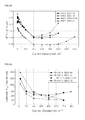
- FIG. 3 a - FIG. 3 b show Tafel slopes taken from corrected polarization curve data of MEA-N (MEA having no silica in the electrode layer) ( FIG. 3 a ) and MEA-C (MEA having silica only within a cathode layer) ( FIG. 3 b ). Data are corrected by measured ohmic losses and crossover.
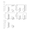
- FIG. 4 shows mass activity values of MEA-N and MEA-C; Tafel slopes of MEA-N and MEA-C; Pt oxide formation charge (Q Pt-oxide ) values of MEA-N and MEA-C; electrochemical surface area (ECA) of MEA-N and MEA-C; specific activity values of MEA-N and MEA-C.
- ECA electrochemical surface area
- FIG. 5 shows schematic depiction of specific adsorption of the sulfonate groups (—SO 3 ⁇ ) on Pt; and mitigation of specific adsorption by the sulfonate groups (—SO 3 ⁇ ) on Pt due to the self-assembly between positively charged silica particles and the negatively charged sulfonate groups.
- FIG. 6 a - FIG. 6 f show electrochemical characteristics of MEAs.
- FIG. 6 a shows high frequency resistance (HFR)-uncorrected polarization curves
- FIG. 6 b shows HFR-corrected polarization curves
- FIG. 6 c shows HFR values at 100% RH
- FIG. 6 d shows HFR values at 50% RH
- FIG. 6 e and FIG. 6 f show the cathode charge-transfer resistance (R CT ) of MEAs at 100% RH and 50% RH, respectively.
- R CT cathode charge-transfer resistance
- FIG. 7 shows bright field TEM images of amorphous silica particles synthesized by the in situ sol-gel reaction of tetraethoxysilane (TEOS) in a Nafion ionomer solution without Pt, and an EDS spectrum of selected amorphous silica particles.
- TEOS tetraethoxysilane
- FIGS. 8 a -8 b show XRD patterns of MEA-C and MEA-N.
- FIG. 9 shows TEM image of MEA-N, particle size distribution of MEA-N without silica nanoparticles, TEM image of MEA-C, and particle size distribution of MEA-C with silica nanoparticles.
- FIG. 10 shows the results of TG analysis of MEA-N without Pt/C and MEA-C without Pt/C. A heating rate of 10° C. min ⁇ 1 is used.
- FIG. 11 a - FIG. 11 b show pore size distributions in membrane electrode assemblies (MEAs) with and without SiO 2 nanoparticles analyzed by mercury porosimetry (Autopore IV 9500, Micrometrics) ( FIG. 11 a ), and pore size distributions in MEAs calculated from nitrogen adsorption data using the BJH method ( FIG. 11 b ).
- FIG. 12 shows dark-field TEM image of catalyst layer in MEA-C, and the corresponding EDS elemental mapping of the same catalyst layer region, indicating spatial distribution of (b) Pt (red), (c) Si (green) and (d) S (blue).
- the images are obtained on FE-TEM (JEM 2100F, JEOL) at an accelerating voltage of 200 kV.
- FIG. 14 shows photographic views of 2 wt % Nafion solution dissolved in IPA solvent, wherein FIG. 14 represents Nafion solution without silica, and FIG. 14 represents Nafion solution with silica.
- FIG. 15 shows dew-point temperatures of the exhaust gas at the anode as a function of time.
- the cell temperature is set to 70° C.
- Humidified H 2 gas of 50% RH is supplied to the anode at a flow rate of 100 mL min ⁇ 1 and humidified air of 50% RH is supplied to the cathode at a flow rate of 410 mL min ⁇ 1 with a constant current density of 400 mA cm ⁇ 2 underambient pressure.
- FIG. 16 shows a graph illustrating cell potential differences ( ⁇ E) from the initial time to 280 seconds as a function of current density at 100% RH, and a graph illustrating cell potential differences ( ⁇ E) from the initial time to 280 seconds as a function of current density at 50% RH.
- FIG. 17 a - FIG. 17 e show graphs illustrating variations in voltage as a function of time under the conditions of: current density 200 mA cm ⁇ 2 , 100% RH ( FIG. 17 a ); current density 600 mA cm ⁇ 2 , 100% RH ( FIG. 17 b ); current density 1000 mA cm ⁇ 2 , 100% RH ( FIG. 17 c ); current density 200 mA cm ⁇ 2 , 50% RH ( FIG. 17 d ); current density 600 mA cm ⁇ 2 , 50% RH ( FIG. 17 e ); and current density 1000 mA cm ⁇ 2 , 50% RH.
- FIG. 18 shows schematic diagrams illustrating water transport at 50% RH through the MEA-A polymer membrane and through the MEA-C polymer membrane.
- FIG. 19 a - FIG. 19 b show Nyquist plots of MEA-N at 100% RH ( FIG. 19 a ) and at 50% RH ( FIG. 19 b ).
- FIG. 20 a - FIG. 20 b show Nyquist plots of MEA-A at 100% RH ( FIG. 20 a ) and at 50% RH ( FIG. 20 b ).
- FIG. 21 a - FIG. 21 b show Nyquist plots of MEA-C at 100% RH ( FIG. 21 a ) and at 50% RH ( FIG. 21 b ).
- FIG. 22 a - FIG. 22 b show Nyquist plots of MEA-C/A at 100% RH ( FIG. 22 a ) and at 50% RH ( FIG. 22 b ).
- a membrane-electrode assembly for a fuel cell including a cathode, an anode and an electrolyte membrane disposed between the cathode and the anode, wherein the cathode includes a first support and a cathode electrode catalyst layer, the anode includes a second support and an anode electrode catalyst layer, a hygroscopic inorganic material is contained in the cathode electrode catalyst layer, and no hygroscopic inorganic material is contained in the anode electrode catalyst layer.
- a membrane-electrode assembly for a fuel cell including a cathode, an anode and an electrolyte membrane disposed between the cathode and the anode, wherein the cathode includes a first support and a cathode electrode catalyst layer, the anode includes a second support and an anode electrode catalyst layer, a hygroscopic inorganic material is contained in the cathode electrode catalyst layer, and the hygroscopic inorganic material is amorphous silica nanoparticles having an average particle size of 5 nm or less.
- the hygroscopic inorganic material may be silica nanoparticles, which are amorphous nanoparticles having an average particle size of 0.5-10 nm, preferably 1-5 nm.
- the silica nanoparticles may have a Q3/Q4 ratio of 1-3, preferably 1.5-2.5, more preferably 1.6-2, most preferably 1.65-1.75, and specifically 1.69-1.72 (based on 29 Si NMR spectra).
- Q3 means the number of silicon atoms bonded to three other silicon atoms through oxygen
- Q4 means the number of silicon atoms bonded to four other silicon atoms through oxygen.
- the silica nanoparticles may be derived from TEOS, wherein no Si resonance peak is observed in 29 Si NMR spectra for determination of non-hydrolyzed TEOS.
- the electrode catalyst layers may provide a current density of 400-800 mA/cm 2 , preferably 500-750 mA/cm 2 , more preferably 600-700 mA/cm 2 , and most preferably 650-670 mA/cm 2 , at 0.6 V under 50% RH, and show a mass activity value of 15-25 A/g pt , preferably 16-23 A/g pt , more preferably 17-21 A/g pt , and most preferably 18-20 A/g pt , at 0.9 V iR-free under 50% RH.
- a method for producing a membrane-electrode assembly for a fuel cell including: forming a dispersion by dispersing Pt/C and Nafion into an aqueous alcoholic solution; adding a TEOS solution and Nafion ionomer to the dispersion to provide a catalyst ink; and forming a catalyst layer on an electrolyte membrane by using the catalyst ink.
- the one-step process including the following operations causes degradation of the final quality of a fuel cell as well as the quality of the resultant catalyst:
- TEOS is hydrolyzed in-situ and negatively charged sulfonate groups of Nafion are bound with positively charged silica through electrical attraction during the condensation reaction.
- bonding occurs via self-assembly.
- Such self-assembled silica has a very small size less than 5 nm and is dispersed uniformly in a catalyst layer without aggregation of silica particles.
- the inorganic materials cause aggregation.
- the present disclosure avoids such aggregation.
- the sulfonate groups contained in Nafion is weakly negatively charged and show specific adsorption on a platinum catalyst surface, resulting in degradation of Pt activity.
- the negatively charged sulfonate groups are distributed around the positively charged silica by way of self-assembly through electrical attraction, resulting in mitigation of specific adsorption of sulfonate groups on a Pt catalyst surface. This leads to a significant increase in Pt activity, resulting in a decrease in amount of Pt needed per unit area of catalyst.
- the —OH functional groups of silica participate in hydrogen bonding with water.
- the water contained in the silica is supplied to the catalyst layer and the polymer membrane under low humidity, thereby improving the low-humidity performance.
- a composite catalyst layer including a Nafion ionomer self-assembled with SiOH 2 + , obtained from an in situ sol-gel process of tetraethoxysilane (TEOS) at pH ⁇ 2.
- TEOS tetraethoxysilane
- One of the characteristics of the present disclosure is using no acid catalyst (e.g. HCl). It is observed that when an acid catalyst is used additionally, the resultant silica has an increased size and shows non-uniformity in shape.
- an acid catalyst e.g. HCl
- the significant enhancement of the water content of Nafion ionomers is determined under a dehydrated condition by preparing a novel composite catalyst layer including a Nafion ionomer self-assembled with SiOH 2 + , obtained from an in situ sol-gel process of tetraethoxysilane (TEOS) at pH ⁇ 2. Further, it is verified that the experimental methods for measuring the water transport in the polymer membrane are applicable to all types of MEA. Most importantly, the method disclosed herein does not require an excessive amount of time or solvent to accomplish the sol-gel reaction of TEOS at high temperatures, as compared with ex situ methods that have been reported previously. To the best of our knowledge, there have been no studies that attempt to improve the performance of cells at low humidity with an MEA that utilizes in situ sol-gel processes of TEOS in a Nafion solution with Pt/C.
- the strong stabilization and steric hindrance effect of self-assembled Nafion—SiO 2 prevent the grain growth of the SiO 2 nanoparticles, which leads to a uniform distribution of SiO 2 nanoparticles having a size of ⁇ 5 nm in the electrode.
- the catalyst ink is sprayed, it is dried at 80° C. to remove the residual solvent and further promote the condensation reaction ( FIG. 1 ).
- the novel composite catalyst layer enhances the performance of the cell significantly, from 476 mA cm ⁇ 2 to 655 mA cm ⁇ 2 at 0.6 V under 50% RH, and improves the mass activity value from 8.3 A g pt ⁇ 1 to 18.9 A g pt ⁇ 1 , at 0.9 V iR-free under 50% RH. Further, the specific activity increases from 52.5 ⁇ A cm ⁇ 2 to 122.5 ⁇ A cm ⁇ 2 under 50% RH.
- the experiments are carried out under various conditions designated as shown: 1) the MEA with TEOS only at the cathode catalyst layer (MEA-C); 2) the MEA with TEOS only at the anode catalyst layer (MEA-A); 3) the MEA without TEOS at both the anode and cathode catalyst layers (MEA-N); and 4) the MEA with TEOS at both the anode and cathode catalyst layers (MEA-C/A).
- a Nafion binder solution with TEOS which includes carbon black (Vulcan XC-72) without Pt, is sprayed onto an NRE 212 membrane to form silica nanoparticles ( FIG. 7 ).
- amorphous silica particles smaller than 5 nm are observed.
- the XRD results show that no peaks associated with silica are observable, which also indicates that silica exists in the amorphous state ( FIG. 8 ).
- FIG. 9 TEM micrographs of MEA-N and MEA-C show that the Pt catalyst and silica are distinguished easily.
- the bimodal particle size distribution show that the amorphous silica particles, which are ⁇ 4.0 nm, exist only within the catalyst layer of MEA-C.
- the TGA measurement indicates that the total amount of silica in the MEA-C without Pt/C is 0.9 wt %, while the percentage of the residual mass of MEA-N without Pt/C is 0.8 wt % ( FIG. 10 ).
- the pore structure is determined by using Hg porosimetry and the BJH method ( FIG. 11 ).
- the pores formed by the Pt/C catalyst layers may be classified into primary pores (i.e., pores formed between the primary carbon particles) and secondary pores (i.e., pores formed between the carbon agglomerates).
- primary pores i.e., pores formed between the primary carbon particles
- secondary pores i.e., pores formed between the carbon agglomerates.
- the uniform distribution of Si in the TEM-EDS image of MEA-C is caused by the Si—OH groups instead of the ethyl groups of TEOS.
- the change in the proton resistance of the catalyst layer is investigated after the addition of TEOS.
- a silicon atom, which is bonded to three other silicon atoms through oxygen, may be depicted as HO—Si—(O—Si) 3 and is generally denoted as Q3, with a chemical shift of approximately ⁇ 100 ppm.
- Si—(O—Si) 4 denoted as Q4, has a chemical shift of approximately ⁇ 110 ppm. As shown in FIG.
- Amorphous silica has two types of surface groups, i.e., singly Si-coordinated and doubly Si-coordinated functionalities.
- the estimated affinity constant for the protonation of doubly-coordinated Si 2 —O 0 is extremely low, which means that these groups may be considered as inert, as is generally accepted.
- the surfaces of singly-coordinated groups i.e., silanol groups
- the silanol groups ionize, producing mobile protons that associate and dissociate from the silica surface.
- a specific Nafion solution is prepared under low pH conditions as follows: the Nafion DE 521 solution (5 wt %, DuPont) and TEOS solution in isopropyl alcohol (IPA)/DI water is dispersed to form a mixture and to facilitate the hydrolysis of TEOS, whereby the mixture is sprayed directly onto each side of a Nafion NRE 212 membrane at 80° C. Subsequently, the Nafion membrane with the silica nanoparticles is dissolved in IPA for 140 h at 25° C. to form 1 wt % solutions.
- IPA isopropyl alcohol
- the Nafion ionomer solution with silica has larger particles, i.e., a hydrodynamic diameter of 930 nm, as compared to the Nafion ionomer solution without silica.
- a hydrodynamic diameter of 930 nm As the negatively charged sulfonate groups (—SO 3 ⁇ ) in Nafion assemble on the positively charged SiOH 2 + groups, due to electrostatic attraction ( FIG. 2 b ), the concentration of Nafion in the vicinity of SiO 2 increases and the dangling chains in Nafion become incorporated into other Nafion ionomers via hydrophobic interactions with the Nafion backbone, leading to a greater negative charge than that of the individual Nafion ionomer.
- Wood et al. (2009) demonstrated the morphological rearrangement between the hydrophobic backbone and hydrophilic side chains in Nafion at the interface between Nafion and Pt using neutron reflectometry. They revealed that more —SO 3 ⁇ groups are present in the region of Pt—O and that the hydrophobic portion of Nafion is pushed away from the oxide interface during the ORR. However, the highly-aggregated —SO 3 H groups may suppress the ORR kinetics occurring on the surface of the Pt due to the specific adsorption of —SO 3 H groups on Pt.
- the decrease in the number of water molecules per —SO 3 H group increases the concentration of —SO 3 H at the interface between the Pt and the ionomer, which results in a large decrease in mass activity (MA) at low RH.
- MA mass activity
- the self-assembly process between positively charged SiOH 2 + groups and negatively charged —SO 3 ⁇ groups in Nafion may reduce the specific adsorption of —SO 3 H groups on the surface of Pt—O, thereby enhancing the ORR kinetics in the cathode catalyst layer at low RH. As can be seen from FIG. 3 and FIG.
- the MA values of MEA-C and MEA-N at 100% RH and 0.9 V iR-free are 23.8 and 11.4 A g Pt ⁇ 1 , respectively.
- the Tafel slopes of MEA-C and MEA-N are ⁇ 55.5 and ⁇ 57.7 mV dec ⁇ 1 , respectively.
- the MA and the Tafel slope are calculated from the iR-corrected I-V curve under O 2 conditions and ambient pressure. The proton resistance in the ionomer binder of the catalyst layer is not corrected. At each current, there is an 18 min wait for the cell to stabilize and then the voltage of the cell is measured.
- the MA is defined as the current at 0.9 V iR-free per unit Pt mass).
- the higher value of the MA of MEA-C also indicates that H 2 O molecules generated by the ORR on the Pt electrode can be adsorbed directly by the silanol groups, which may increase the number of water molecules per —SO 3 H group and mitigate a specific adsorption by the —SO 3 ⁇ groups on the Pt catalysts.
- the Pt oxide formation charge (Q Pt-oxide ) is obtained at different RH conditions.
- the Q Pt-oxide of MEA-C is much higher than that of MEA-N under 100 and 50% RH. Since H 2 O molecules are related directly to chemical equations 3 and 4, a low concentration of H 2 O on the surface of Pt may lead to the suppression of Q pt-oxide at low RH conditions.
- the presence of silica nanoparticles in the vicinity of Pt nanoparticles may increase the water concentration on the surface of Pt, thereby enhancing the formation of Pt oxide at low RH.
- Cyclic voltammetry is conducted in order to measure the electrochemical surface area (ECA) of Pt at 70° C.
- ECA electrochemical surface area
- the ECA of MEA-C decreases from 17.3 m 2 g Pt ⁇ 1 at 100% RH to 15.4 m 2 g Pt ⁇ 1 at 50% RH ( FIG. 4 d ).
- the ECA decreases from 17.7 m 2 g Pt ⁇ 1 at 100% RH to 15.8 m 2 g Pt ⁇ 1 at 50% RH.
- the ECA for hydrogen adsorption/desorption in the CV profile depends on the size of the Pt particles, the binder structure, the cell temperature, the technique used to prepare the electrode and the flow rate of the reactant during the CV measurement.
- the theoretical ECA of the Pt nanoparticles used herein is 65.5 m 2 g Pt ⁇ 1 .
- the diameter of the Pt nanoparticles calculated from the TEM images is 4.58 ⁇ 0.46 nm ( FIG. 9 a ). The diameters of the Pt nanoparticles are unchanged when the TEOS solution is added.
- Hydrolyzed alkoxysilanes may migrate to the negatively charged sulfonate groups (—SO 3 ⁇ ) due to the rapid increase in the zeta potential ( ⁇ ) at pH ⁇ 2, thereby forming a core-shell structure.
- the Nafion ionomer with a core-shell structure cannot penetrate deeply into the primary pores of the electrode and the utilization of Pt is unaffected.
- the significant reduction of the primary pores in the electrode is attributed to the silica nanoparticles.
- the specific activity of Pt is calculated. As a consequence, the specific activity of Pt in MEA-C is found to be much greater than that of MEA-N ( FIG. 4 e ).
- Polarization experiments are conducted in a galvano-static mode. An electronic load is used to maintain a constant current. At each current, the cell is allowed to stabilize for 18 min, after which the voltage of the cell is measured.
- HFR high frequency resistance
- the performance of the MEA-C cell at 50% RH does not decrease significantly in comparison to that at 100% RH, i.e., the current densities of MEA-C and MEA-N at 50% RH and 0.6 V are 655 mA cm ⁇ 2 and 476 mA cm ⁇ 2 , respectively.
- the water transport inside the polymer membrane is determined mainly by the electro-osmotic drag (i.e., the dragging of water molecules from the anode to the cathode by the current-carrier protons), back-diffusion (i.e., the transfer of water into the membrane due to the concentration gradient of the water from the cathode to the anode) and convection (i.e., water movement that occurs due to pressure gradients between the cathode and the anode).
- the convection effect is generally negligible as compared to the effects of electro-osmotic drag and back diffusion because there is no pressure difference between the anode and the cathode.
- electro-osmotic drag and back diffusion dominate the water transport inside the polymer membrane of a PEFC.
- MEA-C has a lower HFR value as compared to the other MEAs. Furthermore, the HFR values of MEA-C are much lower than the others at 50% RH. This may be attributed to the enhanced back diffusion.
- the catalyst layer of the cathode is more easily dehydrated than the catalyst layer of the anode due to excessive water loss caused by the high stoichiometric air flow. This phenomenon has a detrimental effect on back diffusion in the PEFC due to the low concentration of water in the catalyst layer of the cathode.
- the performance of the cell may be increased significantly due to sufficient water transport from the cathode to the anode. Consequently, it is important to maintain a high concentration of water in the catalyst layer of the cathode under conditions of low humidity.
- the electrode is dehydrated, the chemically adsorbed water in SiO 2 is released into the electrode, which increases the concentration of water at the cathode as compared to the anode.
- a higher concentration of water at the cathode enhances back diffusion via the polymer membrane and then the advantage of water transport from the cathode side to the anode side offers excellent proton conductivity to the polymer membrane under dehydration conditions.
- the anode has SiO 2 nanoparticles, the amount of water transported by back diffusion decreases due to the small difference between the concentrations of water at the cathode and the anode.
- the HFR values of MEA-A and MEA-C/A at 50% and 100% RH are greater than the other HFR values.
- a humidity sensor (Viasensor HS-1000) is connected to the outlet of the anode to measure the vapor pressure of the water at a constant current density of 400 mA cm ⁇ 2 at 50% RH.
- the dew point of the anode exhaust gas in MEA-C is greater than the dew points of the exhaust gases from the other MEAs.
- the dew points of MEA-C, MEAA, MEA-C/A and MEA-N are 53.6 ⁇ 0.3, 49.7 ⁇ 0.2, 52.2 ⁇ 0.2, and 52.2 ⁇ 0.4° C., respectively.
- the dew points are in the following increasing order: MEA-A ⁇ MEA-N ⁇ MEA-C/A ⁇ MEA-C.
- the dew point of the inlet gas at the anode is 55.2 ⁇ 0.1° C.
- FIG. 16 shows the differences in the cell potential ( ⁇ E) between an initial time and 280 s as a function of the current density.
- ⁇ E cell potential
- FIG. 17 also shows the variation of voltage as a function of time for various RH conditions and various current density conditions. As shown in FIG. 17 d - FIG. 17 f , the performance of MEA-A is strongly dependent on the applied current density and operation time at 50% RH.
- the voltage increases between the initial time and 25 s for MEA-A, which is greater than the others at 50% RH. This may be attributed to the change in the water transport through the polymer membrane. (See FIG. 18 ).
- the concentration of water at the catalyst layer of the anode (CL a ) is greater than that at the catalyst layer of the cathode (CL c ) due to the high flow rate on the cathode side and the chemically adsorbed water in the SiO 2 .
- the water molecules are transported from the anode side to the cathode side through the polymer membrane via to back diffusion caused by the difference in the concentration of water.
- the water molecules are also transported from the anode side to the cathode side due to electro-osmotic drag.
- the water content of the polymer membrane decreases significantly in the vicinity of the catalyst layer on the anode, resulting in a higher overpotential due to the increase in the resistance to proton transfer in the polymer membrane.
- the concentration of water at the CL c increases over time because water molecules are produced by the ORR and water transport from the cathode side to the anode side increases.
- the water content of the polymer membrane increases due to back diffusion caused by an increase in water molecules at the cathode side at low RH, leading to a decreased resistance to proton transfer in the polymer membrane.
- the water transport from the cathode side to the anode side may not be changed due to the high concentration of water at the CL c .
- the amount of water at the CL c increases over time, and thus back diffusion from the cathode side to the anode side is enhanced.
- the direction of water transport via the polymer membrane is not changed as compared to the MEA-N.
- the difference in the voltage between the two MEAs is not significantly different.
- phase separation occurs between the hydrophilic sulfonic acid groups and the hydrophobic backbone in the Nafion ionomer, resulting in a spherical ionic cluster structure interconnected by narrow channels of sulfonic acid groups.
- the SiO 2 nanoparticles can be impregnated into the negatively charged, spherical —SO 3 ⁇ groups due to the high ⁇ potential of the silica surface at low pH, resulting in a core-shell structure in the electrode.
- Doping silica in the Nafion ionomer will have two opposing effects on proton transport in the catalyst layer.
- a desirable effect is that the concentration of water will be increased by the formation of hydrogen bonds between water and the hydroxyl groups of the silica.
- An undesirable effect is that the proton pathway will be blocked by silica particles due to the high silica content, as well as the large size of the silica particles and the residual ethyl groups on the surface of the silica.
- the Nafion-based catalyst layer according to the present disclosure contains approximately 0.9 wt % SiO 2 nanoparticles, has smaller sized silica particles and there are no residual ethyl groups to hinder the transfer of protons in the catalyst layer.
- the R—SO 3 H—SiO 2 is dissociated fully to form R—SO 3 H and HO—Si—O in the catalyst layer, which does not have a detrimental effect on the proton conductivity of the Nafion ionomer at high RH.
- the proton resistance values in the Nafion ionomer based catalyst layer on the cathode for MEA-N and MEA-C are 8.6 and 7.3 m ⁇ cm 2 , respectively.
- the average thicknesses of the catalyst layers of MEA-N and MEA-C on the cathode are 24.4 ⁇ 0.7 and 24.7 ⁇ 0.8 ⁇ m, respectively). Further, FIG.
- the cathode charge transfer resistance which consists of electron and proton transfer resistance, at the interface between the Pt catalyst and the binder as a function of current density.
- the cathode charge transfer resistance of MEA-C is much lower than the resistance of the others.
- the interfacial contact between the Vulcan carbons decreases, resulting in a significant increase of the resistance to electron charge transfer.
- graphitic carbon is used as the supporting material for Pt according to the present disclosure. Consequently, it is possible to decrease the effect of heterocyclic sulfur on the aggregation of silica colloids. Further, the core-shell structure of the SiO 2 nanoparticles and Nafion ionomer does not restrict the interfacial contact between the graphitic carbons.
- the proton resistance values in the catalyst layers for MEA-N and MEA-C are 119.3 and 91.2 m ⁇ cm 2 , respectively. Further, at 50% RH, the cathode charge transfer resistance of MEA-C is much lower than the resistance of the others, indicating that the chemically adsorbed water molecules in the SiO 2 nanoparticles are released into the Nafion binder, thereby increasing proton hopping through the hydrogen bond network of the water molecules in the catalyst layer.
- Tetraethoxysilane (TEOS) (99.999%, Sigma-Aldrich Co.) was used as the oxide precursor.
- Commercial Pt supported on graphitized carbon 60 wt %, Johnson-Matthey was prepared by mixing solutions with 2-propanol, deionized (DI) water and a solution of Nafion DE 521 (5 wt % Nafion, 45 ⁇ 3 wt % water, 48 ⁇ 3 wt % 1-propanol, ⁇ 4 wt % ethanol with an ion exchange capacity (IEC) of 0.95-1.03 meq g ⁇ 1 , DuPont) without acid or base.
- DI deionized
- Nafion DE 521 5 wt % Nafion DE 521
- IEC ion exchange capacity
- the anode and cathode Pt loadings were approximately 0.50 mg Pt cm ⁇ 2 and all the cathodes and/or anodes had 30 wt % ionomer and around 0.9 wt % SiO 2 .
- a mixture of Pt/C and the Nafion ionomer was sonicated for 20 min and mixed by a stirrer for 40 min.
- the selected catalyst ink was prepared by adding equal masses of the TEOS solution and the solid Nafion ionomer into a prepared mixture of the catalyst ink.
- the anode and cathode catalyst inks were sonicated for an additional 10 min and then stirred for 20 min.
- the MEA with an active area of 25 cm 2 was fabricated by the spray method on a 50 ⁇ m-thick Nafion NRE 212 membrane (DuPont). Then, the MEA was dried at 80° C. to remove the residual solvents and to further promote the polycondensation reaction, through which H 2 O and C 2 H 5 OH are removed.
- the anode and cathode gases were humidified by passing them through bubbler-type humidifiers.
- the humidifiers of both the cathode and anode were calibrated with a humidity sensor (Viasensor HS-1000). All of the unit cell experiments were conducted at 70° C. and the temperature of the gas lines to the anode and the cathode were always set at 10° C. above the temperature of the humidifier to avoid the condensation of water vapor.
- the anode was fed with humidified H 2 gas at a constant flow rate of 100 mL min ⁇ 1 and the cathode was fed with humidified air at a constant flow rate of 410 mL min ⁇ 1 (all at ambient pressure).
- Electrochemical impedance spectroscopy (EIS) measurements were conducted using an HCP-803 analyzer (BioLogic, Science Instruments). At each current, the cell was allowed to stabilize for 18 min, after which the voltage of the cell was measured. All EIS spectra were obtained under the same operating conditions as a measurement test for the polarization curve.
- the impedance spectra were measured in a constant current mode at 40, 100, 600, 800, 1000, 1200 and 1400 mA cm ⁇ 2 by sweeping frequencies over a range of 1000 kHz-100 mHz with 20 points/decade. The impedance spectra were fit using ZView software.
- the cathode and the anode were purged with N 2 (1500 mL min ⁇ 1 ) and H 2 (350 mL min ⁇ 1 ) and then cyclic voltammetry (CV) was performed to measure the electrochemical surface area (ECA) of Pt using an EIS potentiostat.
- ECA electrochemical surface area
- the potential range and the scan rate were 0.04-1.2 V (vs. RHE) and 20 mV s ⁇ 1 , respectively.
- the proton resistance was measured within the electrode via a one-dimensional transmission-line model under an H 2 -fed anode (reference/counter electrode) and a N 2 -purged cathode (working electrode).
- the cathode and the anode were purged with N 2 (900 mL min ⁇ 1 ) and H 2 (900 mL min ⁇ 1 ).
- TG 209 F3 Tarsus Thermal gravimetric analysis
- the technology known as 29 Si solid-state NMR, is a well-established means of determining the coordination environments of 29 Si nuclei, which provides the condensation degree of the silica network.
- the MEA-C without Pt/C was cut into very small fragments that loaded onto a 7 mm rotor.
- Solid-state NMR spectra were recorded on a 400 MHz Bruker Avance spectrometer operating at a frequency of 80 MHz for the 29 Si nucleus and using the magic-angle spinning technique. The sample spinning rate was 10 kHz.
- the morphologies of the silica particles and Pt/C were examined using a transmission electron microscope (TEM) (FEI Tecnai G2-20 STWIN) and a field emission scanning electron microscope (FE-SEM) (Hitachi S-4700).
- TEM transmission electron microscope
- FE-SEM field emission scanning electron microscope
- the Si in the catalyst layer was measured by energy dispersive X-ray spectroscopy (EDS) using an FE-TEM (JEM-2100F, Jeol, Japan, Installed at Korea Basic Science Institute) instrument.
- the size distribution of the ionomer in the Nafion solution was measured with a dynamic light scattering (DLS) spectrometer (Zetasizer Nano ZS, Malvern Instruments).
- the distributions of the pore sizes of the catalyst layers were obtained by mercury porosimetry (Autopore IV 9500, Micromeritics). Specific surface areas were determined by the Brunauer-Emmett-Teller (BET) method with Micromeritics ASAP 2010 using liquid N 2 at 77° K.
- the total pore volume was calculated from the amount of vapor adsorbed at a relative pressure (P/P 0 ) close to unity, where P and P 0 are the measured and the equilibrium pressures, respectively.
- a humidity sensor (Viasensor HS-1000) was used to measure the vapor pressure of water at a constant current density of 400 mA cm ⁇ 2 .
- a humidity sensor was connected at the outlet of the anode in order to compare the water transport via the polymer membrane.
Landscapes
- Chemical & Material Sciences (AREA)
- General Chemical & Material Sciences (AREA)
- Chemical Kinetics & Catalysis (AREA)
- Electrochemistry (AREA)
- Manufacturing & Machinery (AREA)
- Engineering & Computer Science (AREA)
- Life Sciences & Earth Sciences (AREA)
- Sustainable Development (AREA)
- Sustainable Energy (AREA)
- Composite Materials (AREA)
- Organic Chemistry (AREA)
- Analytical Chemistry (AREA)
- Inorganic Chemistry (AREA)
- Inert Electrodes (AREA)
- Fuel Cell (AREA)
Abstract
Description
-
- Addition of silica mitigates specific adsorption of sulfonate groups contained in a Nafion ionomer on a Pt catalyst layer in a high-voltage region where the role of a catalyst predominates, resulting in improvement of ORR performance.
- While the related art is merely directed to improvement under low-humidity conditions by introducing an inorganic material, the present disclosure provides improvement of the ORR performance in a high-voltage range of a Pt catalyst not only under low-humidity conditions but also under normal operating conditions, resulting in reduction of catalyst consumption.
- Addition of silica leads to a change in direction of net water transport into a direction toward an anode from a cathode due to a difference in water concentration between a cathode and an anode. This helps a membrane disposed between the cathode and the anode not to be dried, resulting in significant improvement of the quality of an MEA under low-humidity conditions.
- While externally synthesized SiO2 is added during the preparation of catalyst slurry according to the related art, a silica precursor (TEOS) is added during the preparation of catalyst slurry according to the present disclosure. This allows Nafion to be utilized as an acid catalyst by virtue of its low pH and causes hydrolysis of TEOS on MEA catalyst slurry. Particularly, a Nafion ionomer and a silica surface undergo self-assembly with each other due to their potential characteristics, thereby preventing silica particles from forming large particle aggregates. As a result, the silica formed according to the present disclosure has a very small size less than 5 nm and is dispersed uniformly within an electrode layer. This solves aggregation of silica particles and provides benefits in terms of long-term operation.
- Further, it is observed that the effect of silica addition upon improvement of the quality of an MEA is significantly higher when silica is applied only to a cathode as compared with those effects obtained when silica is applied only to an anode or to both electrodes.
-
- mixing Pt/C, 2-propanol (IPA), water and Nafion, and dispersing Pt/C and Nafion with ultrasonic waves to form a catalyst ink;
- adding TEOS solution and solid Nafion ionomer to the catalyst ink; and
- forming a catalyst layer on an electrolyte membrane by using the catalyst ink, particularly by spraying the catalyst ink onto a Nafion membrane, followed by drying.
Si—O−+H3O+
Si—OH0+H3O+
Pt+H2O→Pt—OHad+H+ +e − (3)
Pt—OHad+H2O→Pt—O+H3O+ +e − (4)
Claims (2)
Applications Claiming Priority (2)
| Application Number | Priority Date | Filing Date | Title |
|---|---|---|---|
| KR1020120079169A KR101381149B1 (en) | 2012-07-20 | 2012-07-20 | Catalyst layer prepared by in-situ sol-gel reaction of tetraethoxysilane in Nafion ionomer solution with Pt/C for polymer electrolyte fuel cell |
| KR10-2012-0079169 | 2012-07-20 |
Publications (2)
| Publication Number | Publication Date |
|---|---|
| US20140023952A1 US20140023952A1 (en) | 2014-01-23 |
| US9559363B2 true US9559363B2 (en) | 2017-01-31 |
Family
ID=49946808
Family Applications (1)
| Application Number | Title | Priority Date | Filing Date |
|---|---|---|---|
| US13/742,975 Active US9559363B2 (en) | 2012-07-20 | 2013-01-16 | Method for preparing catalyst layer by in-situ sol-gel reaction of tetraethoxysilane in Nafion ionomer solution |
Country Status (2)
| Country | Link |
|---|---|
| US (1) | US9559363B2 (en) |
| KR (1) | KR101381149B1 (en) |
Families Citing this family (10)
| Publication number | Priority date | Publication date | Assignee | Title |
|---|---|---|---|---|
| TWI499926B (en) * | 2014-09-09 | 2015-09-11 | Nuvoton Technology Corp | Simulating equivalent circuit of electrostatic discharge protection device and simulation method thereof |
| JP6160591B2 (en) * | 2014-10-24 | 2017-07-12 | トヨタ自動車株式会社 | Catalyst electrode layer, membrane electrode assembly, and fuel cell |
| JP6151321B2 (en) * | 2015-08-27 | 2017-06-21 | 株式会社ノリタケカンパニーリミテド | Electrode material |
| KR102141881B1 (en) * | 2016-03-30 | 2020-08-06 | 코오롱인더스트리 주식회사 | Nanostructured electrode for polymer electrolyte membrane fuel cell, and method for manufacturing the same |
| US10749200B2 (en) * | 2016-04-22 | 2020-08-18 | National University Corporation Nagoya University | Non-humidified proton-conductive membrane, method for producing the same, and fuel cell |
| KR102272379B1 (en) * | 2017-06-23 | 2021-07-02 | 코오롱인더스트리 주식회사 | Electrode with organic metal-oxide, method for manufacturing the same, membrane-electrode assembly comprising the same, and fuel cell comprising the membrane-electrode assembly |
| CN108598538B (en) * | 2018-04-10 | 2020-08-25 | 中国地质大学(武汉) | A kind of in-situ non-destructive modification method of Nafion membrane |
| KR102229663B1 (en) * | 2019-04-11 | 2021-03-19 | 한국에너지기술연구원 | Catalyst electrode of three-phase sepatation and manufacturing method for the same |
| FR3106505B1 (en) * | 2020-01-23 | 2022-01-28 | Faurecia Systemes Dechappement | HYBRID PROTON EXCHANGE MEMBRANE |
| CN118693294B (en) * | 2024-08-22 | 2024-11-08 | 江苏科润膜材料有限公司 | Sulfonated mesoporous silica in-situ modified anode catalyst layer and preparation method and application thereof |
Citations (6)
| Publication number | Priority date | Publication date | Assignee | Title |
|---|---|---|---|---|
| US20090107330A1 (en) * | 2007-10-30 | 2009-04-30 | Yunfeng Gu | Amorphous silica hybrid membrane structure |
| JP2010010101A (en) | 2008-06-30 | 2010-01-14 | Toshiba Corp | Cathode for fuel cell |
| US20100092840A1 (en) * | 2007-03-16 | 2010-04-15 | Sekisui Chemical Co., Ltd. | Electrode binder, electrode, membrane-electrode assembly and polymer electrolyte fuel cell |
| US20100178583A1 (en) * | 2006-09-07 | 2010-07-15 | Nanyang Technological University | Electrode composite material |
| US20100196790A1 (en) * | 2007-09-10 | 2010-08-05 | Fujifilm Corporation | Membrane and electrode assembly and fuel cell |
| US20110200914A1 (en) * | 2010-02-16 | 2011-08-18 | Chao-Yang Wang | High power direct oxidation fuel cell |
Family Cites Families (3)
| Publication number | Priority date | Publication date | Assignee | Title |
|---|---|---|---|---|
| JP4044026B2 (en) | 2002-11-05 | 2008-02-06 | 松下電器産業株式会社 | Fuel cell |
| KR100803671B1 (en) * | 2006-06-08 | 2008-02-19 | 한국과학기술연구원 | Membrane electrode assembly for fuel cell, manufacturing method thereof and fuel cell using the membrane electrode assembly |
| US7947410B2 (en) | 2008-08-22 | 2011-05-24 | Toyota Motor Engineering & Manufacturing North America, Inc. | Fuel cell electrodes with triazole modified polymers and membrane electrode assemblies incorporating same |
-
2012
- 2012-07-20 KR KR1020120079169A patent/KR101381149B1/en active Active
-
2013
- 2013-01-16 US US13/742,975 patent/US9559363B2/en active Active
Patent Citations (7)
| Publication number | Priority date | Publication date | Assignee | Title |
|---|---|---|---|---|
| US20100178583A1 (en) * | 2006-09-07 | 2010-07-15 | Nanyang Technological University | Electrode composite material |
| US20100092840A1 (en) * | 2007-03-16 | 2010-04-15 | Sekisui Chemical Co., Ltd. | Electrode binder, electrode, membrane-electrode assembly and polymer electrolyte fuel cell |
| US20100196790A1 (en) * | 2007-09-10 | 2010-08-05 | Fujifilm Corporation | Membrane and electrode assembly and fuel cell |
| US20090107330A1 (en) * | 2007-10-30 | 2009-04-30 | Yunfeng Gu | Amorphous silica hybrid membrane structure |
| JP2010010101A (en) | 2008-06-30 | 2010-01-14 | Toshiba Corp | Cathode for fuel cell |
| US8187745B2 (en) | 2008-06-30 | 2012-05-29 | Kabushiki Kaisha Toshiba | Cathode for fuel cell |
| US20110200914A1 (en) * | 2010-02-16 | 2011-08-18 | Chao-Yang Wang | High power direct oxidation fuel cell |
Also Published As
| Publication number | Publication date |
|---|---|
| KR20140013186A (en) | 2014-02-05 |
| US20140023952A1 (en) | 2014-01-23 |
| KR101381149B1 (en) | 2014-04-10 |
Similar Documents
| Publication | Publication Date | Title |
|---|---|---|
| US9559363B2 (en) | Method for preparing catalyst layer by in-situ sol-gel reaction of tetraethoxysilane in Nafion ionomer solution | |
| Woo et al. | Current understanding of catalyst/ionomer interfacial structure and phenomena affecting the oxygen reduction reaction in cathode catalyst layers of proton exchange membrane fuel cells | |
| Li et al. | Effect of nano-size of functionalized silica on overall performance of swelling-filling modified Nafion membrane for direct methanol fuel cell application | |
| JP6956390B2 (en) | Electrocatalysts for electrochemical devices, electrode catalyst layers for electrochemical devices, membrane / electrode assemblies for electrochemical devices, electrochemical devices, methods for manufacturing electrode catalysts for electrochemical devices, and membrane / electrode assemblies for electrochemical devices. Production method | |
| Uchida et al. | Effect of the state of distribution of supported Pt nanoparticles on effective Pt utilization in polymer electrolyte fuel cells | |
| CN105594033B (en) | Catalyst carbon dust and catalyst, electrode catalyst layer, membrane-electrode assembly and the fuel cell using the catalyst carbon dust | |
| Islam et al. | Enhanced durability of Pt/C catalyst by coating carbon black with silica for oxygen reduction reaction | |
| Yang et al. | Preparation of Nafion/Pt-containing TiO2/graphene oxide composite membranes for self-humidifying proton exchange membrane fuel cell | |
| Curnick et al. | Nafion®-stabilised Pt/C electrocatalysts with efficient catalyst layer ionomer distribution for proton exchange membrane fuel cells | |
| Otsuji et al. | Effect of water management in membrane and cathode catalyst layers on suppressing the performance hysteresis phenomenon in anion-exchange membrane fuel cells | |
| KR20070063532A (en) | Carbon supported catalyst having reduced water retention | |
| Wang et al. | UV-crosslinkable anthracene-based ionomer derived gas “Expressway” for anion exchange membrane fuel cells | |
| Wang et al. | Preparation and performance of nano silica/Nafion composite membrane for proton exchange membrane fuel cells | |
| Shintani et al. | A model for mesoporous carbon-supported platinum catalyst/electrolyte interfaces in polymer electrolyte fuel cells | |
| Han et al. | A modified cathode catalyst layer with optimum electrode exposure for high current density and durable proton exchange membrane fuel cell operation | |
| KR20210110121A (en) | Antioxidant, polymer electrolyte membrane for fuel cell comprising same and manufacturing method thereof | |
| Jayawickrama et al. | Effect of polymer-coating on carbon blacks for Pt utilization efficiency of polymer electrolyte membrane fuel cells | |
| CN113140739A (en) | Fuel cell gas diffusion layer, preparation method thereof, membrane electrode assembly and fuel cell | |
| KR102953758B1 (en) | Catalyst for Fuel Cell, Method for Fabricating the Same and Fuel Cell Comprising the Same | |
| Wang et al. | Stability and performance of in-situ formed phosphosilicate nanoparticles in phosphoric acid-doped polybenzimidazole composite membrane fuel cells at elevated temperatures | |
| CN118867272A (en) | A fuel cell microporous layer and preparation method thereof | |
| Ma et al. | An ionic liquid-mediated hydrogen-bond network: a pathway to high-efficiency PEMFCs with unlocked active sites of Pt/C catalysts | |
| JP4418653B2 (en) | Electrode catalyst layer for polymer electrolyte fuel cell, electrode for polymer electrolyte fuel cell, polymer electrolyte fuel cell | |
| Eastcott et al. | Electrochemical studies of ceramic carbon electrodes for fuel cell systems: A catalyst layer without sulfonic acid groups | |
| KR20210002017A (en) | Catalyst for Fuel Cell, Method for Manufacturing The Same, and Membrane Electrode Assembly Comprising The Same |
Legal Events
| Date | Code | Title | Description |
|---|---|---|---|
| AS | Assignment |
Owner name: KOREA INSTITUTE OF ENERGY RESEARCH, KOREA, REPUBLI Free format text: ASSIGNMENT OF ASSIGNORS INTEREST;ASSIGNORS:YIIM, SUNG-DAE;KIM, TAEYOUNG;PARK, SEOK-HEE;AND OTHERS;REEL/FRAME:029642/0375 Effective date: 20130104 |
|
| AS | Assignment |
Owner name: KOREA INSTITUTE OF ENERGY RESEARCH, KOREA, REPUBLI Free format text: CORRECTIVE ASSIGNMENT TO CORRECT THE TYPOGRAPHICAL ERROR IN FIRST ASSIGNOR'S LAST NAME PREVIOUSLY RECORDED ON REEL 029642 FRAME 0375. ASSIGNOR(S) HEREBY CONFIRMS THE LAST NAME WAS LISTED AS "YIIM" AND SHOULD BE "YIM";ASSIGNORS:YIM, SUNG-DAE;KIM, TAEYOUNG;PARK, SEOK-HEE;AND OTHERS;REEL/FRAME:030463/0959 Effective date: 20130104 |
|
| STCF | Information on status: patent grant |
Free format text: PATENTED CASE |
|
| CC | Certificate of correction | ||
| MAFP | Maintenance fee payment |
Free format text: PAYMENT OF MAINTENANCE FEE, 4TH YR, SMALL ENTITY (ORIGINAL EVENT CODE: M2551); ENTITY STATUS OF PATENT OWNER: SMALL ENTITY Year of fee payment: 4 |
|
| MAFP | Maintenance fee payment |
Free format text: PAYMENT OF MAINTENANCE FEE, 8TH YR, SMALL ENTITY (ORIGINAL EVENT CODE: M2552); ENTITY STATUS OF PATENT OWNER: SMALL ENTITY Year of fee payment: 8 |