US9557135B2 - Water gun - Google Patents

Water gun Download PDF

Info

Publication number
US9557135B2
US9557135B2 US14/720,064 US201514720064A US9557135B2 US 9557135 B2 US9557135 B2 US 9557135B2 US 201514720064 A US201514720064 A US 201514720064A US 9557135 B2 US9557135 B2 US 9557135B2
Authority
US
United States
Prior art keywords
water
suction inlet
inner space
cylindrical inner
barrel
Prior art date
Legal status (The legal status is an assumption and is not a legal conclusion. Google has not performed a legal analysis and makes no representation as to the accuracy of the status listed.)
Active
Application number
US14/720,064
Other versions
US20160341515A1 (en
Inventor
Fa-Kuang Liang
Current Assignee (The listed assignees may be inaccurate. Google has not performed a legal analysis and makes no representation or warranty as to the accuracy of the list.)
Dongguan Tiger Point Metal and Plastic Products Co Ltd
Original Assignee
Dongguan Tiger Point Metal and Plastic Products Co Ltd
Priority date (The priority date is an assumption and is not a legal conclusion. Google has not performed a legal analysis and makes no representation as to the accuracy of the date listed.)
Filing date
Publication date
Application filed by Dongguan Tiger Point Metal and Plastic Products Co Ltd filed Critical Dongguan Tiger Point Metal and Plastic Products Co Ltd
Priority to US14/720,064 priority Critical patent/US9557135B2/en
Assigned to DONGGUAN TIGER POINT METAL & PLASTIC PRODUCTS CO., LTD. reassignment DONGGUAN TIGER POINT METAL & PLASTIC PRODUCTS CO., LTD. ASSIGNMENT OF ASSIGNORS INTEREST (SEE DOCUMENT FOR DETAILS). Assignors: LIANG, FA-KUANG
Publication of US20160341515A1 publication Critical patent/US20160341515A1/en
Application granted granted Critical
Publication of US9557135B2 publication Critical patent/US9557135B2/en
Active legal-status Critical Current
Anticipated expiration legal-status Critical

Links

Images

Classifications

    • FMECHANICAL ENGINEERING; LIGHTING; HEATING; WEAPONS; BLASTING
    • F41WEAPONS
    • F41BWEAPONS FOR PROJECTING MISSILES WITHOUT USE OF EXPLOSIVE OR COMBUSTIBLE PROPELLANT CHARGE; WEAPONS NOT OTHERWISE PROVIDED FOR
    • F41B9/00Liquid ejecting guns, e.g. water pistols, devices ejecting electrically charged liquid jets, devices ejecting liquid jets by explosive pressure
    • F41B9/0003Liquid ejecting guns, e.g. water pistols, devices ejecting electrically charged liquid jets, devices ejecting liquid jets by explosive pressure characterised by the pressurisation of the liquid
    • F41B9/0031Liquid ejecting guns, e.g. water pistols, devices ejecting electrically charged liquid jets, devices ejecting liquid jets by explosive pressure characterised by the pressurisation of the liquid the liquid being pressurised at the moment of ejection
    • F41B9/0037Pressurisation by a piston
    • F41B9/004Pressurisation by a piston the piston movement being mechanically coupled to the trigger movement, e.g. the piston being part of the trigger

Definitions

  • the present invention relates to a water gun for children to play with, especially to a water gun disposed with a jetting outlet and at least one suction inlet for providing functions of rapid water suction and inflation.
  • a water inlet and a water outlet of water guns available on the market now are located at the same hole having a diameter ranging from 4 to 8 centimeters.
  • the water gun has the simple structure, it is unable to suck water rapidly and spray water far away for a long time.
  • the diameter of the water inlet should be increased. The larger the diameter of the water inlet, the shorter the water shooting distance and the shooting time. If the user wants a further shooting distance for a longer time, the diameter of the water outlet should be smaller. But the water suction speed is lowered and the suction time is increased.
  • the design doesn't match user's requirements for water guns.
  • the conventional water gun is used less efficiently due to two opposite functions including water shooting and water suction performed through the same hole. There is room for improvement and a need to provide a water gun with novel structure.
  • a front plate of a water gun is disposed with at least one suction inlet and a jetting outlet for water suction and water shooting respectively.
  • the suction inlet is disposed around the jetting outlet, and having a larger diameter or area than that of the jetting outlet.
  • the suction inlet works like a one-way valve so that water is only able to enter the water gun, without being discharged.
  • the jetting outlet has a smaller diameter compared with the diameter of the suction inlet.
  • a threaded insert is disposed just outside the jetting outlet.
  • the threaded insert can be mounted with a ball inflating needle for inflation of inflatable toys or balls.
  • the threaded insert is connected to a bike pump hose for inflation of bicycle tires.
  • FIG. 1 is a perspective view of an embodiment according to the present invention
  • FIG. 2 is a cross sectional view of an embodiment according to the present invention.
  • FIG. 3 is a front view of a front plate without being disposed with a non-return valve of an embodiment according to the present invention
  • FIG. 4 is a cross sectional view taken along line A-A of the embodiment in FIG. 3 according to the present invention.
  • FIG. 5 is a front view of a front plate without being arranged with a non-return valve of an embodiment according to the present invention
  • FIG. 6 is a cross sectional view taken along line B-B of the embodiment in FIG. 5 according to the present invention.
  • FIG. 7 is a front view of an embodiment of a non-return valve according to the present invention.
  • FIG. 8 is a side view of the embodiment in FIG. 7 according to the present invention.
  • FIG. 9 is a front view of a front plate of another embodiment according to the present invention.
  • FIG. 10 is a front view of a front plate without being disposed with a thread of another embodiment according to the present invention.
  • FIG. 11 is a cross sectional view taken along line C-C of the embodiment in FIG. 10 according to the present invention.
  • FIG. 12 is a perspective view of a non-return valve of an embodiment according to the present invention.
  • FIG. 13 is a schematic drawing showing water shooting of an embodiment in use according to the present invention.
  • FIG. 15 is a schematic drawing showing an embodiment connected to a bike pump hose while in use according to the present invention.
  • FIG. 16 is a drawing showing the water gun according to the present invention being filled using outside water being sucked into the inner space of the barrel.
  • a water gun of the present invention includes a barrel 10 , a shaft 30 , and a hand grip 20 disposed on a rear end of the shaft 30 .
  • the barrel 10 is formed by a front plate 13 and a rear plate 12 .
  • the shaft 30 is passed through a center of the rear plate 12 of the water gun.
  • a cylinder valve 301 is disposed on a front end of the shaft 30 and is integrated with the shaft 30 .
  • a circular groove for receiving a rubber ring 302 is arranged around the cylinder valve 301 .
  • the cylinder valve 301 is slideable and airtightly fit in the barrel 10 .
  • a jetting outlet 134 is disposed on the front plate 13 while at least one suction inlet 131 is arranged around the jetting outlet 134 .
  • the number of the suction inlet 131 is not limited. In this embodiment, there is only one suction inlet 131 .
  • another embodiment of the present invention includes two suction inlets 131 . Refer from FIG. 10 and FIG. 11 , there are six suction inlets 131 arranged at the front plate 13 .
  • a non-return valve 132 is disposed on an inner face of the suction inlet 131 that is facing an inner space 101 of the barrel 10 .
  • the suction inlet 131 is covered by the non-return valve 132 in an opened or closed state for control of the water only able to enter the inner space 101 of the barrel 10 through the suction inlet 131 in a one-way manner, without being discharged.
  • the non-return valve 132 can be arranged with one connection pin 1321 for closing a suction inlet 131 , as shown in FIG. 5 to FIG. 8 .
  • the non-return valve 132 can be set with one connection pin 1321 for closing two suction inlets 131 at the same time.
  • the non-return valve 132 can also be disposed with two connection pins 1321 for closing a plurality of (six) suction inlets 131 .
  • the non-return valve 132 is opened in relation to the suction inlet 131 due to a suction force when the hand grip 20 is pulled out.
  • water outside the water gun is sucked into the inner space 101 of the water gun through the suction inlet 131 and the jetting outlet 134 .
  • FIG. 16 shows one example of outside water being sucked into the inner space of the barrel.
  • a bucket 60 filled with water 62 , having a surface 64 is provided.
  • the water gun with the barrel 10 , shaft 30 and hand grip 20 is inserted into the bucket of water so that the front end of the water gun is below the surface 64 of the water.
  • suction is created in the barrel and water from the bucket enters the barrel through the suction inlet 131 , which is open.
  • This water 66 in the inner space has a surface 68 , which may be above the surface 64 of the outer water.
  • the suction inlet 131 closes and the water gun may be removed from the bucket to be used.
  • the jetting outlet 134 has functions of water suction and water jetting.
  • the hand grip 20 When the hand grip 20 is pushed in, the inner space 101 is compressed by the cylinder valve 301 .
  • the non-return valve 132 is closed in relation to the suction inlet 131 due to the pressure of the air.
  • the water stored in the inner space 101 is shot out through the jetting outlet 134 .
  • a diameter of the suction inlet 131 can be designed to be a multiple times of a diameter of the jetting outlet 134 .
  • water is drawn into the water gun rapidly through the at least one suction inlet 131 .
  • the water While shooting water, the water is shot further for a longer time due to the one jetting outlet 134 with a much smaller diameter. Therefore the present invention features on at least one suction inlet 131 and the jetting outlet 134 designed for water suction and water shooting respectively.
  • an inner thread 135 is set on a projecting portion to form a threaded insert, located just outside the jetting outlet 134 .
  • the inner thread 135 can be engaged with an outer thread of a ball inflating needle 40 and/or a bike pump hose 50 . Since air and water are both fluids, reacting the same way.
  • the water gun of the present invention can also be applied to inflation of inflatable toys, balls and bike tires. This is another feature of the present invention.

Abstract

A water gun is revealed. The water gun includes a jetting outlet and at least one suction inlet. The jetting outlet is disposed on a front plate of a barrel of the water gun while the suction inlet that works like a one-way valve is arranged around the jetting outlet. When the hand grip is pulled out, water outside is drawn into an inner space of the barrel of the water gun through the at least one suction inlet. The water in the inner space of the barrel of the water glue is unable to flow out through the at least one suction inlet when the hand grip is pushed in. Moreover, an inner thread is arranged outside the jetting outlet and used for connecting a ball inflating needle or a bike pump hose for inflation of inflatable toys or balls.

Description

BACKGROUND OF THE INVENTION
The present invention relates to a water gun for children to play with, especially to a water gun disposed with a jetting outlet and at least one suction inlet for providing functions of rapid water suction and inflation.
Generally, a water inlet and a water outlet of water guns available on the market now are located at the same hole having a diameter ranging from 4 to 8 centimeters. Although the water gun has the simple structure, it is unable to suck water rapidly and spray water far away for a long time. In order to suck water quickly, the diameter of the water inlet should be increased. The larger the diameter of the water inlet, the shorter the water shooting distance and the shooting time. If the user wants a further shooting distance for a longer time, the diameter of the water outlet should be smaller. But the water suction speed is lowered and the suction time is increased. The design doesn't match user's requirements for water guns. The conventional water gun is used less efficiently due to two opposite functions including water shooting and water suction performed through the same hole. There is room for improvement and a need to provide a water gun with novel structure.
SUMMARY OF THE INVENTION
Therefore it is a primary object of the present invention to provide a water gun that sucks water rapidly, having much more fun and uses as an inflation tool.
In order to achieve the above object, a front plate of a water gun is disposed with at least one suction inlet and a jetting outlet for water suction and water shooting respectively. The suction inlet is disposed around the jetting outlet, and having a larger diameter or area than that of the jetting outlet. Thus the water is drawn into the water fun more rapidly. Moreover, the suction inlet works like a one-way valve so that water is only able to enter the water gun, without being discharged. The jetting outlet has a smaller diameter compared with the diameter of the suction inlet. Thus users can shoot water over a greater distance and for a longer time. Thereby the water gun is used more efficiently and having more fun.
A threaded insert is disposed just outside the jetting outlet. The threaded insert can be mounted with a ball inflating needle for inflation of inflatable toys or balls. Or the threaded insert is connected to a bike pump hose for inflation of bicycle tires.
BRIEF DESCRIPTION OF THE DRAWINGS
FIG. 1 is a perspective view of an embodiment according to the present invention;
FIG. 2 is a cross sectional view of an embodiment according to the present invention;
FIG. 3 is a front view of a front plate without being disposed with a non-return valve of an embodiment according to the present invention;
FIG. 4 is a cross sectional view taken along line A-A of the embodiment in FIG. 3 according to the present invention;
FIG. 5 is a front view of a front plate without being arranged with a non-return valve of an embodiment according to the present invention;
FIG. 6 is a cross sectional view taken along line B-B of the embodiment in FIG. 5 according to the present invention;
FIG. 7 is a front view of an embodiment of a non-return valve according to the present invention;
FIG. 8 is a side view of the embodiment in FIG. 7 according to the present invention;
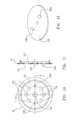
FIG. 9 is a front view of a front plate of another embodiment according to the present invention;
FIG. 10 is a front view of a front plate without being disposed with a thread of another embodiment according to the present invention;
FIG. 11 is a cross sectional view taken along line C-C of the embodiment in FIG. 10 according to the present invention;
FIG. 12 is a perspective view of a non-return valve of an embodiment according to the present invention;
FIG. 13 is a schematic drawing showing water shooting of an embodiment in use according to the present invention;
FIG. 14 is a schematic drawing showing an embodiment used for inflating a ball with an inflating needle according to the present invention;
FIG. 15 is a schematic drawing showing an embodiment connected to a bike pump hose while in use according to the present invention;
FIG. 16 is a drawing showing the water gun according to the present invention being filled using outside water being sucked into the inner space of the barrel.
DETAILED DESCRIPTION OF THE PREFERRED EMBODIMENT
Refer to FIG. 1 and FIG. 2, a water gun of the present invention includes a barrel 10, a shaft 30, and a hand grip 20 disposed on a rear end of the shaft 30. The barrel 10 is formed by a front plate 13 and a rear plate 12. The shaft 30 is passed through a center of the rear plate 12 of the water gun. A cylinder valve 301 is disposed on a front end of the shaft 30 and is integrated with the shaft 30. A circular groove for receiving a rubber ring 302 is arranged around the cylinder valve 301. Thus the cylinder valve 301 is slideable and airtightly fit in the barrel 10.
Refer from FIG. 3 to FIG. 6, a jetting outlet 134 is disposed on the front plate 13 while at least one suction inlet 131 is arranged around the jetting outlet 134. The number of the suction inlet 131 is not limited. In this embodiment, there is only one suction inlet 131. As shown in FIG. 9, another embodiment of the present invention includes two suction inlets 131. Refer from FIG. 10 and FIG. 11, there are six suction inlets 131 arranged at the front plate 13. A non-return valve 132 is disposed on an inner face of the suction inlet 131 that is facing an inner space 101 of the barrel 10. The suction inlet 131 is covered by the non-return valve 132 in an opened or closed state for control of the water only able to enter the inner space 101 of the barrel 10 through the suction inlet 131 in a one-way manner, without being discharged.
The material for the non-return valve 132 is not limited. The material can be metal or plastic. Refer to FIG. 7 and FIG. 8, the non-return valve 132 is a plastic plate having a certain thickness and disposed with a connection pin 1321 on one end thereof. The connection pin 1321 is mounted into a fixing hole 133 on the front plate 13 so that the non-return valve 132 is positioned on the front plate 13 and is in a closed or opened state in relation to the suction inlet 131. Moreover, the shape of the non-return valve 132 and the way of the non-return valve 132 fixed on the front plate 13 are not limited. The non-return valve 132 can be arranged with one connection pin 1321 for closing a suction inlet 131, as shown in FIG. 5 to FIG. 8. Refer to FIG. 9, the non-return valve 132 can be set with one connection pin 1321 for closing two suction inlets 131 at the same time. Refer from FIG. 10 to FIG. 12, the non-return valve 132 can also be disposed with two connection pins 1321 for closing a plurality of (six) suction inlets 131.
Refer to FIG. 2, the non-return valve 132 is opened in relation to the suction inlet 131 due to a suction force when the hand grip 20 is pulled out. Thus water outside the water gun is sucked into the inner space 101 of the water gun through the suction inlet 131 and the jetting outlet 134.
FIG. 16 shows one example of outside water being sucked into the inner space of the barrel. A bucket 60, filled with water 62, having a surface 64 is provided. The water gun with the barrel 10, shaft 30 and hand grip 20 is inserted into the bucket of water so that the front end of the water gun is below the surface 64 of the water. When the hand grip 20 is moved upwardly in the direction of the arrow, suction is created in the barrel and water from the bucket enters the barrel through the suction inlet 131, which is open. This water 66 in the inner space has a surface 68, which may be above the surface 64 of the outer water. When the hand grip no longer moves upwardly, the suction inlet 131 closes and the water gun may be removed from the bucket to be used.
Now the jetting outlet 134 has functions of water suction and water jetting. When the hand grip 20 is pushed in, the inner space 101 is compressed by the cylinder valve 301. Thus the non-return valve 132 is closed in relation to the suction inlet 131 due to the pressure of the air. At the moment, the water stored in the inner space 101 is shot out through the jetting outlet 134. In this embodiment, a diameter of the suction inlet 131 can be designed to be a multiple times of a diameter of the jetting outlet 134. Thus water is drawn into the water gun rapidly through the at least one suction inlet 131. While shooting water, the water is shot further for a longer time due to the one jetting outlet 134 with a much smaller diameter. Therefore the present invention features on at least one suction inlet 131 and the jetting outlet 134 designed for water suction and water shooting respectively.
Refer from FIG. 1 to FIG. 4, an inner thread 135 is set on a projecting portion to form a threaded insert, located just outside the jetting outlet 134. The inner thread 135 can be engaged with an outer thread of a ball inflating needle 40 and/or a bike pump hose 50. Since air and water are both fluids, reacting the same way. The water gun of the present invention can also be applied to inflation of inflatable toys, balls and bike tires. This is another feature of the present invention.
Additional advantages and modifications will readily occur to those skilled in the art. Therefore, the invention in its broader aspects is not limited to the specific details, and representative devices shown and described herein. Accordingly, various modifications may be made without departing from the spirit or scope of the general inventive concept as defined by the appended claims and their equivalents.

Claims (5)

What is claimed is:
1. A water gun comprising:
a barrel having a cylindrical inner space, a front plate disposed with a jetting outlet, and a rear plate,
a hand grip disposed on a rear end of a shaft which is passed through a center of the rear plate of the barrel; and a cylinder valve arranged at a front end of the shaft and slideable airtightly in the cylindrical inner space of the barrel; wherein water outside is drawn into the cylindrical inner space through the jetting outlet when the hand grip is pulled out; wherein the cylindrical inner space is pressed by the cylinder valve so that water in the cylindrical inner space is sprayed out through the jetting outlet when the handle grip is pushed in;
wherein at least one suction inlet that works in a one-way manner is disposed around the jetting outlet;
wherein the water outside is sucked into the cylindrical inner space of the barrel through the at least one suction inlet when the hand grip is pulled out;
wherein the water in the cylindrical inner space of the barrel is unable to flow out through the at least one suction inlet when the hand grip is pushed in.
2. The device as claimed in claim 1, wherein a non-return valve is disposed on an inner face of the at least one suction inlet that is facing the cylindrical inner space of the barrel so that the at least one suction inlet is covered by the non-return valve in an opened or closed state; the non-return valve is in the opened state in relation to the at least one suction inlet due to a suction force and the water outside is sucked into the cylindrical inner space through the at least one suction inlet when the hand grip is pulled out; the cylindrical inner space is compressed by the cylinder valve so that the non-return valve is in the closed state in relation to the at least one suction inlet due to air pressure and water in the cylindrical inner space is unable to flow out through the at least one suction inlet when the hand grip is pushed in.
3. The device as claimed in claim 2, wherein the non-return valve is disposed with at least one connection pin; the at least one connection pin is fit into a fixing hole arranged at the front plate so that the non-return valve is positioned on the front plate and is in the closed state or the opened state in relation to the at least one suction inlet.
4. The device as claimed in claim 3, wherein the at least one connection pin is selected from the group consisting of one connection pin for closing one suction inlet, one connection pin for closing two suction inlets and two connection pins for closing a plurality of suction inlets.
5. The device as claimed in claim 1, wherein an inner thread is set on a projecting portion located just outside the jetting outlet; the inner thread is able to be engaged with an outer thread of a ball inflating needle or a bike pump hose.
US14/720,064 2015-05-22 2015-05-22 Water gun Active US9557135B2 (en)

Priority Applications (1)

Application Number Priority Date Filing Date Title
US14/720,064 US9557135B2 (en) 2015-05-22 2015-05-22 Water gun

Applications Claiming Priority (1)

Application Number Priority Date Filing Date Title
US14/720,064 US9557135B2 (en) 2015-05-22 2015-05-22 Water gun

Publications (2)

Publication Number Publication Date
US20160341515A1 US20160341515A1 (en) 2016-11-24
US9557135B2 true US9557135B2 (en) 2017-01-31

Family

ID=57325258

Family Applications (1)

Application Number Title Priority Date Filing Date
US14/720,064 Active US9557135B2 (en) 2015-05-22 2015-05-22 Water gun

Country Status (1)

Country Link
US (1) US9557135B2 (en)

Cited By (1)

* Cited by examiner, † Cited by third party
Publication number Priority date Publication date Assignee Title
US20170100645A1 (en) * 2015-02-22 2017-04-13 Jeffrey Scott Larson Illuminated ball

Families Citing this family (1)

* Cited by examiner, † Cited by third party
Publication number Priority date Publication date Assignee Title
CN107860261A (en) * 2017-11-20 2018-03-30 黄�俊 The peashooter of quick big flow water intaking

Citations (4)

* Cited by examiner, † Cited by third party
Publication number Priority date Publication date Assignee Title
US1971450A (en) * 1932-10-21 1934-08-28 Bernhard V Heitmulier Fire extinguisher and other pumplike device
US4733799A (en) * 1986-02-24 1988-03-29 Wiskur Darrell D Water cannon toy or like device
US20060200081A1 (en) * 2005-03-01 2006-09-07 Irving Mizus System for access into bodily cavity
US7913880B2 (en) * 2004-09-16 2011-03-29 Easebon Services Limited Squirting toy including a supplemental reservoir system and methods thereof

Patent Citations (4)

* Cited by examiner, † Cited by third party
Publication number Priority date Publication date Assignee Title
US1971450A (en) * 1932-10-21 1934-08-28 Bernhard V Heitmulier Fire extinguisher and other pumplike device
US4733799A (en) * 1986-02-24 1988-03-29 Wiskur Darrell D Water cannon toy or like device
US7913880B2 (en) * 2004-09-16 2011-03-29 Easebon Services Limited Squirting toy including a supplemental reservoir system and methods thereof
US20060200081A1 (en) * 2005-03-01 2006-09-07 Irving Mizus System for access into bodily cavity

Cited By (2)

* Cited by examiner, † Cited by third party
Publication number Priority date Publication date Assignee Title
US20170100645A1 (en) * 2015-02-22 2017-04-13 Jeffrey Scott Larson Illuminated ball
US10434376B2 (en) * 2015-02-22 2019-10-08 Jeffrey Scott Larson Illuminated ball

Also Published As

Publication number Publication date
US20160341515A1 (en) 2016-11-24

Similar Documents

Publication Publication Date Title
US8074838B1 (en) Combined water gun and water balloon launcher and associated method
US6955531B2 (en) Pump for inflating and deflating an inflatable object with a rotatable nozzle assembly
US20050184098A1 (en) Water shield
US9557135B2 (en) Water gun
US8701935B2 (en) Water gun
US20110186595A1 (en) Water Toy Gun
US6234347B1 (en) Pressurized water gun with selective pressurization
US9328834B2 (en) Air valve connecting device
US20110027004A1 (en) Spray brush
US7341504B1 (en) Adjustable sand blasting gun
US8303365B2 (en) Jet propulsion construction toy assembly
US8607774B2 (en) Vortex ring producing gun
US20020016127A1 (en) Water gun having pump with internal passageway
CN210292979U (en) Toy water pistol
US20070289995A1 (en) Steady stream water gun
JP4520864B2 (en) Hand pump
US9827576B2 (en) Nozzle assembly capable of performing suction and high pressure blowing
US10408203B2 (en) Hand air pump with air accumulation function
CN207622605U (en) The peashooter of quick big flow water intaking
TW201520506A (en) A water gun
US20160008832A1 (en) Device Of Spray Gun For Preventing Liquid From Flowing Backward
KR200188049Y1 (en) Air pump
CN109163604B (en) Children toy water gun
CN107860261A (en) The peashooter of quick big flow water intaking
CN210696301U (en) Water gun umbrella

Legal Events

Date Code Title Description
AS Assignment

Owner name: DONGGUAN TIGER POINT METAL & PLASTIC PRODUCTS CO.,

Free format text: ASSIGNMENT OF ASSIGNORS INTEREST;ASSIGNOR:LIANG, FA-KUANG;REEL/FRAME:035745/0360

Effective date: 20150512

STCF Information on status: patent grant

Free format text: PATENTED CASE

FEPP Fee payment procedure

Free format text: SURCHARGE FOR LATE PAYMENT, SMALL ENTITY (ORIGINAL EVENT CODE: M2554); ENTITY STATUS OF PATENT OWNER: SMALL ENTITY

MAFP Maintenance fee payment

Free format text: PAYMENT OF MAINTENANCE FEE, 4TH YR, SMALL ENTITY (ORIGINAL EVENT CODE: M2551); ENTITY STATUS OF PATENT OWNER: SMALL ENTITY

Year of fee payment: 4