US9554087B2 - Information processing device including an image transmission control function - Google Patents
Information processing device including an image transmission control function Download PDFInfo
- Publication number
- US9554087B2 US9554087B2 US13/974,554 US201313974554A US9554087B2 US 9554087 B2 US9554087 B2 US 9554087B2 US 201313974554 A US201313974554 A US 201313974554A US 9554087 B2 US9554087 B2 US 9554087B2
- Authority
- US
- United States
- Prior art keywords
- image
- state
- terminal
- communication counterpart
- picked
- Prior art date
- Legal status (The legal status is an assumption and is not a legal conclusion. Google has not performed a legal analysis and makes no representation as to the accuracy of the status listed.)
- Active, expires
Links
Images


Classifications
-
- H—ELECTRICITY
- H04—ELECTRIC COMMUNICATION TECHNIQUE
- H04N—PICTORIAL COMMUNICATION, e.g. TELEVISION
- H04N7/00—Television systems
- H04N7/14—Systems for two-way working
- H04N7/141—Systems for two-way working between two video terminals, e.g. videophone
-
- H—ELECTRICITY
- H04—ELECTRIC COMMUNICATION TECHNIQUE
- H04N—PICTORIAL COMMUNICATION, e.g. TELEVISION
- H04N23/00—Cameras or camera modules comprising electronic image sensors; Control thereof
- H04N23/60—Control of cameras or camera modules
- H04N23/61—Control of cameras or camera modules based on recognised objects
- H04N23/611—Control of cameras or camera modules based on recognised objects where the recognised objects include parts of the human body
-
- H04N5/23219—
-
- H—ELECTRICITY
- H04—ELECTRIC COMMUNICATION TECHNIQUE
- H04N—PICTORIAL COMMUNICATION, e.g. TELEVISION
- H04N7/00—Television systems
- H04N7/14—Systems for two-way working
- H04N7/141—Systems for two-way working between two video terminals, e.g. videophone
- H04N7/142—Constructional details of the terminal equipment, e.g. arrangements of the camera and the display
-
- H—ELECTRICITY
- H04—ELECTRIC COMMUNICATION TECHNIQUE
- H04N—PICTORIAL COMMUNICATION, e.g. TELEVISION
- H04N7/00—Television systems
- H04N7/14—Systems for two-way working
- H04N7/141—Systems for two-way working between two video terminals, e.g. videophone
- H04N7/147—Communication arrangements, e.g. identifying the communication as a video-communication, intermediate storage of the signals
-
- H—ELECTRICITY
- H04—ELECTRIC COMMUNICATION TECHNIQUE
- H04N—PICTORIAL COMMUNICATION, e.g. TELEVISION
- H04N7/00—Television systems
- H04N7/14—Systems for two-way working
- H04N7/141—Systems for two-way working between two video terminals, e.g. videophone
- H04N7/142—Constructional details of the terminal equipment, e.g. arrangements of the camera and the display
- H04N2007/145—Handheld terminals
Definitions
- the disclosures made herein relate to an information processing device including an image transmission control function.
- a mobile phone terminal including a video call function has been widespread as an example of an information processing device that transmits/receives a facial image.
- This video call function allows voice information and image information, which is obtained through real-time photographing (image pickup) with a camera, to be transmitted/received bidirectionally between a mobile phone terminal used by a calling party and a mobile phone terminal used by a called party. As a result, it is possible to visually grasp a situation of a communication counterpart, which is insufficient with only voice. However, a broad transmission bandwidth is necessary for a communication path including a network due to the bidirectional transmission/reception of the image information.
- the patent documents include one that discloses a technology for performing face recognition processing based on the image information photographed with the camera of the mobile phone terminal and shifting to a voice call mode when a face cannot be recognized.
- a shift is made to the voice call mode even when an attempt is made to look at a picture of a communication counterpart, and hence it is not possible to look at the picture of the communication counterpart.
- an information processing device includes an image pickup unit that picks up an image including a facial image of a speaker; a transmission unit that transmits a picked-up image; a reception unit that receives an image including a facial image picked up by a communication counterpart device; a display unit that displays a received image; and a transmission control unit that inhibits transmission of the image picked up by the image pickup unit in a case where the facial image is not being picked up by the communication counterpart device.
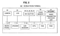
- FIG. 1 illustrates a mobile phone terminal according to an embodiment
- FIG. 2 is a block diagram illustrating a configuration of the mobile phone terminal according to the embodiment
- FIG. 3A is a diagram for illustrating first image transmission control processing
- FIG. 3B is a diagram for illustrating first image transmission control processing
- FIG. 4A is a state transition diagram for illustrating the first image transmission control processing
- FIG. 4B is a state transition diagram for illustrating the first image transmission control processing
- FIG. 4C is a state transition diagram for illustrating the first image transmission control processing
- FIG. 5A is a flowchart for illustrating the first image transmission control processing
- FIG. 5B is a flowchart for illustrating the first image transmission control processing
- FIG. 5C is a flowchart for illustrating the first image transmission control processing
- FIG. 6A is a diagram for illustrating second image transmission control processing
- FIG. 6B is a diagram for illustrating second image transmission control processing
- FIG. 7A is a state transition diagram for illustrating the second image transmission control processing
- FIG. 7B is a state transition diagram for illustrating the second image transmission control processing
- FIG. 7C is a state transition diagram for illustrating the second image transmission control processing
- FIG. 7D is a state transition diagram for illustrating the second image transmission control processing
- FIG. 8A is a flowchart for illustrating the second image transmission control processing
- FIG. 8B is a flowchart for illustrating the second image transmission control processing
- FIG. 8C is a flowchart for illustrating the second image transmission control processing
- FIG. 8D is a flowchart for illustrating the second image transmission control processing
- FIG. 9 is a diagram for illustrating third image transmission control processing.
- FIG. 10 is a diagram for illustrating the third image transmission control processing.
- FIG. 1 and FIG. 2 illustrate a configuration of a mobile phone terminal MT including an image transmission control function according to an embodiment.
- Any portable information terminal such as a laptop personal computer, that includes a control function unit, a communication function unit, an information input function unit, an information display function unit, an information designation function unit, an information retaining function unit, and an image pickup function unit may be employed as the mobile phone terminals MT used by a calling party (calling speaker) and a called party (called speaker) involved in a video call.
- control function unit includes a central processing unit (CPU) serving as a processor, a random access memory (RAM) serving as a work memory, and a read only memory (ROM) that stores a boot program for a startup.
- CPU central processing unit
- RAM random access memory
- ROM read only memory
- the communication function unit includes an antenna 10 , a radio transmitter/receiver unit 11 , a microphone 12 , a speaker 13 , and an ear receiver 14 .
- the information input function unit includes a numeric keypad 20 and various function buttons (keys) 21 and 22
- the information display function unit includes a display 30
- the information designation function unit includes a pointing unit 40 and a cursor moving unit 41 .
- the information retaining function unit includes a nonvolatile flash memory 50 that saves an operating system (OS), various application programs, and various kinds of information (including data) in a rewritable manner
- the image pickup function unit includes a camera 60 .
- the CPUs expand this image transmission control program into the RAMs and execute the program in response to triggers such as requests from the calling party and the called party involved in the video call, in other words, origination of a call through a video call button 22 and answering the call through the video call button 22 .
- the image transmission control program carries out image transmission control processing in cooperation with the above-mentioned hardware components such as the control function unit, the communication function unit, the information input function unit, the information display function unit, the information designation function unit, the information retaining function unit, and the image pickup function unit.
- the mobile phone terminal MT used by the calling party or the called party involved in the video call has a feature in that whether or not an own terminal is allowed to transmit a picked-up image is controlled based on whether or not a facial image is being picked up on a communication counterpart terminal.
- an image transmission inhibition message “inhibition msg” is transmitted from the A-side terminal MT(A) to a mobile phone terminal (B-side terminal) MT(B) used by the called party.
- the B-side terminal MT(B) that has received this image transmission inhibition message “inhibition msg” is inhibited from transmitting the image photographed with the camera 60 of the B-side terminal MT(B).
- an image transmission inhibition cancelling message “inhibition cancelling msg” is transmitted from the A-side terminal MT(A) to the B-side terminal MT(B).
- the B-side terminal MT(B) that has received this image transmission inhibition cancelling message “inhibition cancelling msg” restarts the transmission of the image photographed with the camera 60 of the B-side terminal MT(B).
- FIG. 3A and FIG. 3B illustrate an outline of the first image transmission control processing in time series.
- a state of No. 1 by bidirectionally transmitting/receiving pieces of image information (transmitting/receiving moving images) photographed with the camera 60 of the A-side terminal MT(A) and the camera 60 of the B-side terminal MT(B), the facial image is displayed on the display (LCD) 30 of the communication counterpart terminal.
- LCD display
- a state of No. 2, to which a transition is made from the state of No. 1, indicates a case where the face cannot be recognized (face recognition NG) because a subject other than A's face (here, flower) is being photographed with the camera 60 of the A-side terminal MT(A).
- face recognition NG face recognition NG
- the image transmission inhibition message “inhibition msg” (hereinafter sometimes referred to simply as “inhibition msg”) is transmitted from the A-side terminal MT(A) to the B-side terminal MT(B).
- the B-side terminal MT(B) that has received this “inhibition msg” is controlled so as not to transmit the facial image photographed with the camera 60 of the B-side terminal MT(B) to the A-side terminal MT(A) (stop transmission).
- a state of No. 3, to which a transition is made from the state of No. 2, indicates a case where A's face photographed with the camera 60 of the A-side terminal MT(A) is recognized (face recognition OK).
- the image transmission inhibition cancelling message “inhibition cancelling msg” (hereinafter sometimes referred to simply as “inhibition cancelling msg”) is transmitted from the A-side terminal MT(A).
- the B-side terminal MT(B) that has received this “inhibition cancelling msg” transmits the facial image photographed with the camera 60 of the B-side terminal MT(B) to the A-side terminal MT(A). Therefore, the state returns to a bidirectional image transmission/reception state.
- a state of No. 4, to which a transition is made from the state of No. 3, indicates the case where the face cannot be recognized because, contrary to No. 2, a subject other than B's face (here, automobile) is being photographed with the camera 60 of the B-side terminal MT(B).
- the “inhibition msg” is transmitted from the B-side terminal MT(B) to the A-side terminal MT(A).
- the A-side terminal MT(A) that has received this “inhibition msg” is controlled so as not to transmit the image photographed with the camera 60 of the A-side terminal MT(A) to the B-side terminal MT(B).
- a state of No. 5, to which a transition is made from the state of No. 4, indicates the case where the face cannot be recognized because, in addition, the subject other than A's face is being photographed with the camera 60 of the A-side terminal MT(A).
- the “inhibition msg” is transmitted from the A-side terminal MT(A) to the B-side terminal MT(B).
- the B-side terminal MT(B) that has received this “inhibition msg” is controlled so as not to transmit the image photographed with the camera 60 of the B-side terminal MT(B) to the A-side terminal MT(A). Therefore, a bidirectional image transmission/reception stopped state is effected.
- a state of No. 6, to which a transition is made from the state of No. 5, indicates the case where B's face photographed with the camera 60 of the B-side terminal MT(B) is recognized.
- the “inhibition cancelling msg” is transmitted from the B-side terminal MT(B) to the A-side terminal MT(A).
- the A-side terminal MT(A) that has received the “inhibition cancelling msg” transmits the image photographed with the camera 60 of the A-side terminal MT(A) to the B-side terminal MT(B).
- a state [0] is an initial state in which communication (voice call) using a video call is not being performed, and hence the cameras 60 and the displays (LCDs) 30 are in a stopped state on the mobile phone terminal (A-side terminal) MT(A) used by the calling party and the mobile phone terminal (B-side terminal) MT(B) used by the called party.
- a state [1] is a state in which the image being photographed with the camera 60 of the own terminal (for example, A-side terminal MT(A)) is being transmitted and the image received from the communication counterpart terminal (for example, B-side terminal MT(B)) is not being displayed on the display 30 (image transmitting and display stopped state).
- a state [2] is a state in which the image being photographed with the camera 60 of the own terminal is being transmitted and the image received from the communication counterpart terminal is being displayed on the display 30 (image transmitting and displaying state).
- a state [3] is a state in which the image being photographed with the camera 60 of the own terminal is not being transmitted and the image received from the communication counterpart terminal is being displayed on the display 30 (transmission stopped and displaying state).
- a state [4] is a state in which the image being photographed with the camera 60 of the own terminal is not being transmitted and the image received from the communication counterpart terminal is not being displayed on the display 30 (transmission stopped and display stopped state).
- the image transmission inhibition cancelling message “inhibition cancelling msg” is transmitted to the communication counterpart terminal, and the state remains the state [1].
- the display 30 is stopped from displaying, and a transition is made to the state [1].
- the “inhibition cancelling msg” is transmitted to the communication counterpart terminal, and the state remains the state [2].
- the display 30 is stopped from displaying, and a transition is made to the state [4].
- the “inhibition cancelling msg” is transmitted to the communication counterpart terminal, and the state remains the state [3].
- the “inhibition cancelling msg” is transmitted to the communication counterpart terminal, and the state remains the state [4].
- [S 4 ] It is verified whether or not the face is recognized based on the image being photographed with the camera 60 of the own terminal. If the face is recognized, the procedure advances to Step S 5 , and if the face cannot be recognized, the procedure advances to Step S 19 .
- [S 5 ] It is verified whether or not the “inhibition msg” has been transmitted to the communication counterpart terminal. If the “inhibition msg” has been transmitted, the procedure advances to Step S 20 , and if the “inhibition msg” has not been transmitted, the procedure advances to Step S 6 .
- [S 6 ] It is verified whether or not the “inhibition msg” has been received from the communication counterpart terminal. If the “inhibition msg” has been received, the procedure advances to Step S 21 , and if the “inhibition msg” has not been received, the procedure advances to S 7 .
- [S 7 ] It is verified whether or not the “inhibition cancelling msg” has been received from the communication counterpart terminal. If the “inhibition cancelling msg” has been received, the procedure advances to Step S 22 , and if the “inhibition cancelling msg” has not been received, the procedure advances to S 8 .
- [S 8 ] It is verified whether or not the video call is to be ended. If the video call is to be ended, the procedure advances to Step S 9 , and if the video call is not to be ended, the procedure advances to Step S 2 .
- [S 9 ] It is verified whether or not the image is being transmitted. If being transmitted, the procedure advances to Step S 10 , and if not being transmitted, the procedure advances to Step S 11 .
- Step S 15 It is verified whether or not the “inhibition msg” has been transmitted to the communication counterpart terminal. If the “inhibition msg” has been transmitted, the procedure advances to Step S 25 , and if the “inhibition msg” has not been transmitted, the procedure advances to Step S 16 .
- Step S 16 It is verified whether or not the “inhibition msg” has been received from the communication counterpart terminal. If the “inhibition msg” has been received, the procedure advances to Step S 26 , and if the “inhibition msg” has not been received, the procedure advances to S 17 .
- Step S 17 It is verified whether or not the “inhibition cancelling msg” has been received from the communication counterpart terminal. If the “inhibition cancelling msg” has been received, the procedure advances to Step S 27 , and if the “inhibition cancelling msg” has not been received, the procedure advances to S 18 .
- Step S 18 It is verified whether or not the video call is to be ended. If the video call is to be ended, the procedure advances to Step S 9 , and if the video call is not to be ended, the procedure advances to Step S 13 .
- [S 20 ] The “inhibition cancelling msg” is transmitted to the communication counterpart terminal.
- [S 21 ] The image being photographed with the camera 60 of the own terminal is stopped from being transmitted to the communication counterpart terminal.
- [S 22 ] The image being photographed with the camera 60 of the own terminal is transmitted to the communication counterpart terminal.
- [S 23 ] The image being received from the communication counterpart terminal is displayed on the display 30 .
- the mobile phone terminal (B-side terminal) MT(B) used by the called party verifies whether or not the mobile phone terminal (A-side terminal) MT(A) used by the calling party is referring to the image information obtained from the B-side terminal MT(B) by recognizing the face based on the image information being received by the B-side terminal MT(B).
- the image information being photographed with the camera on the B-side terminal MT(B) side is inhibited from being transmitted to the A-side terminal MT(A), to thereby inhibit needless image information from being transmitted to each other through a special interface.
- FIG. 6A and FIG. 6B illustrate an outline of the second image transmission control processing in time series.
- a state of No. 1 by bidirectionally transmitting/receiving pieces of image information (transmitting/receiving moving images) photographed with the camera 60 of the A-side terminal MT(A) and the camera 60 of the B-side terminal MT(B), the facial image is displayed on the display (LCD) 30 of the communication counterpart terminal.
- LCD display
- the subject other than A's face (here, flower) is being photographed with the camera 60 of the A-side terminal MT(A).
- the B-side terminal MT(B) cannot recognize A's face based on the image received from the A-side terminal MT(A).
- face recognition NG face recognition NG
- the B-side terminal MT(B) is controlled so as not to transmit the facial image photographed with the camera 60 of the B-side terminal MT(B) to the A-side terminal MT(A) (stop transmission).
- a state [0] is an initial state in which communication (voice call) using a video call is not being performed, and hence the cameras 60 and the displays 30 are in a stopped state on the mobile phone terminal (A-side terminal) MT(A) used by the calling party and the mobile phone terminal (B-side terminal) MT(B) used by the called party.
- a state [1] is an image unreceived state in which the image being photographed with the camera 60 of the own terminal (for example, A-side terminal MT(A)) is being transmitted and the image received from the communication counterpart terminal (for example, B-side terminal MT(B)) is not being displayed on the display (LCD) 30 .
- a state [2] is a bidirectional communication state in which the image being photographed with the camera 60 of the own terminal is being transmitted and the image received from the communication counterpart terminal is being displayed on the display 30 .
- a state [3] is an image transmission stopped state in which the image being photographed with the camera 60 of the own terminal is not being transmitted and the image received from the communication counterpart terminal is being displayed on the display 30 .
- the state [4] is the voice-call-in-progress state, and the cameras 60 and the displays 30 included in the own terminal and the communication counterpart terminal are in the stopped state.
- the display 30 is stopped from displaying, and a transition is made to the state [1].
- the display 30 is stopped from displaying, and a transition is made to the state [1].
- Step S 34 It is verified whether or not the face is recognized based on the image received from the communication counterpart terminal. If the face can be recognized, the procedure advances to Step S 35 , and if the face cannot be recognized, the procedure advances to Step S 37 .
- Step S 35 It is verified whether or not the switching is to be performed to the voice call. If the switching is to be performed to the voice call, the procedure advances to Step S 44 , and if the switching is not to be performed to the voice call, the procedure advances to Step S 36 .
- Step S 36 It is verified whether or not the video call is to be ended. If the video call is to be ended, the procedure advances to Step S 47 , and if the video call is not to be ended, the procedure advances to Step S 58 .
- Step S 37 The image photographed with the camera 60 of the own terminal is stopped from being transmitted to the communication counterpart terminal.
- Step S 38 It is verified whether or not the face can be recognized for the fixed time based on the image photographed with the camera 60 of the own terminal. If the face can be recognized, the procedure advances to Step S 39 , and if the face cannot be recognized, the procedure advances to Step S 45 .
- Step S 39 It is verified whether or not the switching is to be performed to the voice call. If the switching is to be performed to the voice call, the procedure advances to Step S 45 , and if the switching is not to be performed to the voice call, the procedure advances to Step S 57 .
- [S 40 ] The image is not being received from the communication counterpart terminal, and hence the display 30 is stopped from displaying.
- [S 41 ] It is verified whether or not the image is being received from the communication counterpart terminal. If the image is being received from the communication counterpart terminal, the procedure advances to Step S 50 , and if the image is not being received from the communication counterpart terminal, the procedure advances to Step S 42 .
- [S 42 ] It is verified whether or not the switching is to be performed to the voice call. If the switching is to be performed to the voice call, the procedure advances to Step S 51 , and if the switching is not to be performed to the voice call, the procedure advances to Step S 43 .
- Step S 43 It is verified whether or not the video call is to be ended. If the video call is to be ended, the procedure advances to Step S 49 , and if the video call is not to be ended, the procedure advances to Step S 41 .
- Step S 44 The image photographed with the camera 60 of the own terminal is stopped from being transmitted to the communication counterpart terminal.
- Step S 45 The display 30 is stopped from displaying.
- S 46 The camera 60 is stopped.
- [S 52 ] The voice call is started. [S 53 ] It is verified whether or not the switching is to be performed to the video call. If the switching is to be performed to the video call, the procedure advances to Step S 55 , and if the switching is not to be performed to the video call, the procedure advances to Step S 54 . [S 54 ] It is verified whether or not the voice call is to be ended. If the voice call is to be ended, the procedure advances to Step S 56 , and if the voice call is not to be ended, the procedure advances to Step S 52 . [S 55 ] The voice call ending processing is performed. [S 56 ] The voice call ending processing is performed.
- [S 57 ] It is verified whether or not the video call is to be ended. If the video call is to be ended, the procedure advances to Step S 48 , and if the video call is not to be ended, the procedure advances to Step S 32 .
- [S 58 ] It is verified whether or not the transmission of the own image is being stopped. If the transmission of the image is being stopped, the procedure advances to Step S 59 , and if the transmission of the image is not being stopped, the procedure advances to Step S 32 .
- [S 59 ] The image photographed with the camera 60 of the own terminal starts to be transmitted to the communication counterpart terminal.
- FIG. 9 illustrates a first outline of third image transmission control processing in time series.
- This first outline of the third image transmission control processing indicates a case where the mobile phone terminal (A-side terminal) MT(A) used by the calling party has the above-mentioned second image transmission control processing function but the mobile phone terminal (B-side terminal) MT(B) used by the called party does not have the above-mentioned second image transmission control processing function.
- This state of No. 1 corresponds to the state [2] illustrated in the state transition diagrams of the second image transmission control processing illustrated in FIG. 7A , FIG. 7B , FIG. 7C and FIG. 7D .
- the A-side terminal MT(A) and the B-side terminal MT(B) repeat the processing of a loop that starts from Step S 31 and returns to Step S 32 through Steps S 32 , S 33 , S 34 , S 35 , S 36 , and S 58 of the flowcharts illustrated in FIG. 8A , FIG. 8B , FIG. 8C and FIG. 8D .
- the subject other than B's face (here, automobile) is being photographed with the camera 60 of the B-side terminal MT(B).
- the A-side terminal MT(A) cannot recognize B's face based on the image received from the B-side terminal MT(B).
- face recognition NG face recognition NG
- the A-side terminal MT(A) is controlled so as not to transmit the facial image photographed with the camera 60 of the A-side terminal MT(A) to the B-side terminal MT(B) (stop transmission).
- This state of No. 2 corresponds to the states [1] and [3] illustrated in the state transition diagrams of the second image transmission control processing illustrated in FIG. 7A , FIG. 7B , FIG. 7C and FIG. 7D .
- the A-side terminal MT(A) repeats the processing of a loop that starts from Step S 32 and returns to Step S 32 through Steps S 33 , S 34 , S 37 , S 38 , S 39 , and S 57 of the flowcharts illustrated in FIG. 8A , FIG. 8B , FIG. 8C and FIG. 8D .
- the B-side terminal MT(B) repeats the processing of a loop that starts from Step S 32 and returns to Step S 41 through Steps S 40 , S 41 , S 42 , and S 43 of the flowcharts illustrated in FIG. 8A , FIG. 8B , FIG. 8C and FIG. 8D .
- the subject other than A's face is being photographed with the camera 60 of the A-side terminal MT(A).
- the A-side terminal MT(A) comes to a state in which the face cannot be recognized based on the image photographed with the camera 60 of the A-side terminal MT(A). Therefore, it is determined that the images are being stopped bidirectionally, and bearer switching to the voice call is performed, to thereby set a voice-call-in-progress state represented by the state of No. 4.
- This state of No. 3 corresponds to a transient state [*] that transitions from the state [3] to the state [4] in the state transition diagrams of the second image transmission control processing illustrated in FIG. 7A , FIG. 7B , FIG. 7C and FIG. 7D .
- the state of No. 4 corresponds to the state [4] illustrated in the state transition diagrams of the second image transmission control processing illustrated in FIG. 7A , FIG. 7B , FIG. 7C and FIG. 7D .
- the A-side terminal MT(A) repeats the processing of a loop that starts from Step S 38 and returns to Step S 52 through Steps S 45 , S 46 , S 52 , S 53 , and S 54 of the flowcharts illustrated in FIG. 8A , FIG. 8B , FIG. 8C and FIG. 8D .
- the B-side terminal MT(B) repeats the processing of a loop that starts from Step S 42 and returns to Step S 52 through Steps S 51 , S 46 , S 52 , S 53 , and S 54 of the flowcharts illustrated in FIG. 8A , FIG. 8B , FIG. 8C and FIG. 8D .
- FIG. 10 illustrates a second outline of the third image transmission control processing in time series.
- This second outline of the third image transmission control processing indicates a case where the A-side terminal MT(A) has the above-mentioned second image transmission control processing function but the B-side terminal MT(B) does not have the above-mentioned second image transmission control processing function.
- This state of No. 1 corresponds to the state [2] illustrated in the state transition diagrams of the second image transmission control processing illustrated in FIG. 7A , FIG. 7B , FIG. 7C and FIG. 7D .
- the A-side terminal MT(A) and the B-side terminal MT(B) repeat the processing of a loop that starts from Step S 31 and returns to Step S 32 through Steps S 32 , S 33 , S 34 , S 35 , S 36 , and S 58 of the flowcharts illustrated in FIG. 8A , FIG. 8B , FIG. 8C and FIG. 8D .
- the subject other than A's face (here, flower) is being photographed with the camera 60 of the A-side terminal MT(A).
- the image transmission control function according to the embodiment is not installed, and hence the image of the subject other than A's face received from the A-side terminal MT(A) is displayed as it is, and the image of B's face photographed with the camera 60 of the B-side terminal MT(B) is transmitted to the A-side terminal MT(A) as it is.
- This state of No. 2 of the A-side terminal MT(A) corresponds to the state [2] illustrated in the state transition diagrams of the second image transmission control processing illustrated in FIG. 7A , FIG. 7B , FIG. 7C and FIG. 7D . Further, in the state of No. 2, the A-side terminal MT(A) repeats the processing of a loop that starts from Step S 31 and returns to Step S 32 through Steps S 32 , S 33 , S 34 , S 35 , S 36 , and S 58 of the flowcharts illustrated in FIG. 8A , FIG. 8B , FIG. 8C and FIG. 8D .
- the subject other than B's face here, automobile
- the A-side terminal MT(A) cannot recognize the face based on the image received from the B-side terminal MT(B), and hence the A-side terminal MT(A) is controlled so as not to transmit the image photographed with the camera 60 of the A-side terminal MT(A) to the B-side terminal MT(B) (stop transmission).
- This state of No. 3 of the A-side terminal MT(A) corresponds to the state [3] illustrated in the state transition diagrams of the second image transmission control processing illustrated in FIG. 7A , FIG. 7B , FIG. 7C and FIG. 7D . Further, in the state of No. 3, the A-side terminal MT(A) repeats the processing of a loop that starts from Step S 32 and returns to Step S 32 through Steps S 33 , S 34 , S 37 , S 38 , S 39 , and S 57 of the flowcharts illustrated in FIG. 8A , FIG. 8B , FIG. 8C and FIG. 8D .
- the subject other than A's face is being photographed with the camera 60 of the A-side terminal MT(A).
- the A-side terminal MT(A) comes to a state in which the face cannot be recognized based on the image photographed with the camera 60 of the A-side terminal MT(A). Therefore, it is determined that the images are being stopped bidirectionally, and bearer switching to the voice call is performed, to thereby set a voice-call-in-progress state represented by the state of No. 5.
- This state of No. 4 corresponds to a transient state [*] that transitions from the state [3] to the state [4] in the state transition diagrams of the second image transmission control processing illustrated in FIG. 7A , FIG. 7B , FIG. 7C and FIG. 7D .
- the state of No. 5 corresponds to the state [4] illustrated in the state transition diagrams of the second image transmission control processing illustrated in FIG. 7A , FIG. 7B , FIG. 7C and FIG. 7D .
- the A-side terminal MT(A) repeats the processing of a loop that starts from Step S 38 and returns to Step S 52 through Steps S 45 , S 46 , S 52 , S 53 , and S 54 of the flowcharts illustrated in FIG. 8A , FIG. 8B , FIG. 8C and FIG. 8D .
- the processing of the embodiment described above is provided as a computer-executable program, and can be provided by a recording medium such as a CD-ROM or a flexible disk or via a communication line.
Landscapes
- Engineering & Computer Science (AREA)
- Multimedia (AREA)
- Signal Processing (AREA)
- Two-Way Televisions, Distribution Of Moving Picture Or The Like (AREA)
- Telephone Function (AREA)
- Telephonic Communication Services (AREA)
Abstract
Description
-
- [Patent document 1] Japanese Patent Laid-Open Publication No. JP 2009-4959
- [Patent document 2] Japanese Patent Laid-Open Publication No. JP 2009-60277
Claims (4)
Applications Claiming Priority (1)
| Application Number | Priority Date | Filing Date | Title |
|---|---|---|---|
| PCT/JP2011/057987 WO2012131932A1 (en) | 2011-03-30 | 2011-03-30 | Information processing device including image transmission control function |
Related Parent Applications (1)
| Application Number | Title | Priority Date | Filing Date |
|---|---|---|---|
| PCT/JP2011/057987 Continuation WO2012131932A1 (en) | 2011-03-30 | 2011-03-30 | Information processing device including image transmission control function |
Publications (2)
| Publication Number | Publication Date |
|---|---|
| US20130342633A1 US20130342633A1 (en) | 2013-12-26 |
| US9554087B2 true US9554087B2 (en) | 2017-01-24 |
Family
ID=46929758
Family Applications (1)
| Application Number | Title | Priority Date | Filing Date |
|---|---|---|---|
| US13/974,554 Active 2031-12-22 US9554087B2 (en) | 2011-03-30 | 2013-08-23 | Information processing device including an image transmission control function |
Country Status (4)
| Country | Link |
|---|---|
| US (1) | US9554087B2 (en) |
| EP (1) | EP2693745A4 (en) |
| JP (1) | JP5614494B2 (en) |
| WO (1) | WO2012131932A1 (en) |
Families Citing this family (8)
| Publication number | Priority date | Publication date | Assignee | Title |
|---|---|---|---|---|
| KR20180039402A (en) * | 2016-10-10 | 2018-04-18 | 주식회사 하이퍼커넥트 | Device and method of displaying images |
| US11553157B2 (en) | 2016-10-10 | 2023-01-10 | Hyperconnect Inc. | Device and method of displaying images |
| JP6967065B2 (en) * | 2017-03-09 | 2021-11-17 | 株式会社 資生堂 | Information processing equipment, programs, and information processing methods |
| KR101932844B1 (en) | 2017-04-17 | 2018-12-27 | 주식회사 하이퍼커넥트 | Device and method of making video calls and method of mediating video calls |
| KR102282963B1 (en) | 2019-05-10 | 2021-07-29 | 주식회사 하이퍼커넥트 | Mobile, server and operating method thereof |
| KR102311603B1 (en) | 2019-10-01 | 2021-10-13 | 주식회사 하이퍼커넥트 | Mobile and operating method thereof |
| KR102293422B1 (en) | 2020-01-31 | 2021-08-26 | 주식회사 하이퍼커넥트 | Mobile and operating method thereof |
| KR20210115442A (en) | 2020-03-13 | 2021-09-27 | 주식회사 하이퍼커넥트 | Report evaluation device and operating method thereof |
Citations (8)
| Publication number | Priority date | Publication date | Assignee | Title |
|---|---|---|---|---|
| EP1631084A2 (en) | 2004-08-30 | 2006-03-01 | Nec Corporation | Communication terminal apparatus, television telephone control method, and television telephone control program |
| JP2006253775A (en) | 2005-03-08 | 2006-09-21 | Canon Inc | Video phone equipment |
| US20070003254A1 (en) | 2005-06-30 | 2007-01-04 | Sony Corporation | Interactive communication apparatus and status signaling method |
| JP2008182466A (en) | 2007-01-24 | 2008-08-07 | Funai Electric Co Ltd | Video telephone |
| JP2009004959A (en) | 2007-06-20 | 2009-01-08 | Toshiba Corp | Mobile device |
| JP2009060277A (en) | 2007-08-30 | 2009-03-19 | Casio Hitachi Mobile Communications Co Ltd | Portable terminal device and portable terminal processing program |
| US7564476B1 (en) * | 2005-05-13 | 2009-07-21 | Avaya Inc. | Prevent video calls based on appearance |
| US20100097440A1 (en) * | 2008-10-21 | 2010-04-22 | Samsung Electronics Co., Ltd. | Communication mode switching method and apparatus for mobile terminal |
Family Cites Families (4)
| Publication number | Priority date | Publication date | Assignee | Title |
|---|---|---|---|---|
| JP2004350315A (en) * | 2004-07-22 | 2004-12-09 | Toshiba Corp | Communication terminal device |
| JP2006100980A (en) * | 2004-09-28 | 2006-04-13 | Nec Access Technica Ltd | Portable telephone terminal with tv telephone function and on/off-control method of its video image and voice |
| JP4468418B2 (en) * | 2007-07-24 | 2010-05-26 | 株式会社エヌ・ティ・ティ・ドコモ | Control device and mobile communication system |
| US20100315483A1 (en) * | 2009-03-20 | 2010-12-16 | King Keith C | Automatic Conferencing Based on Participant Presence |
-
2011
- 2011-03-30 JP JP2013506939A patent/JP5614494B2/en not_active Expired - Fee Related
- 2011-03-30 EP EP11862357.8A patent/EP2693745A4/en not_active Withdrawn
- 2011-03-30 WO PCT/JP2011/057987 patent/WO2012131932A1/en not_active Ceased
-
2013
- 2013-08-23 US US13/974,554 patent/US9554087B2/en active Active
Patent Citations (11)
| Publication number | Priority date | Publication date | Assignee | Title |
|---|---|---|---|---|
| EP1631084A2 (en) | 2004-08-30 | 2006-03-01 | Nec Corporation | Communication terminal apparatus, television telephone control method, and television telephone control program |
| US20060050141A1 (en) * | 2004-08-30 | 2006-03-09 | Nec Corporation | Communication terminal apparatus, television telephone control method, and television telephone control program |
| JP2006067436A (en) | 2004-08-30 | 2006-03-09 | Nec Corp | Communication terminal unit, videophone control method and its program |
| JP2006253775A (en) | 2005-03-08 | 2006-09-21 | Canon Inc | Video phone equipment |
| US7564476B1 (en) * | 2005-05-13 | 2009-07-21 | Avaya Inc. | Prevent video calls based on appearance |
| US20070003254A1 (en) | 2005-06-30 | 2007-01-04 | Sony Corporation | Interactive communication apparatus and status signaling method |
| JP2007013693A (en) | 2005-06-30 | 2007-01-18 | Sony Corp | Bidirectional communication device and status notification method |
| JP2008182466A (en) | 2007-01-24 | 2008-08-07 | Funai Electric Co Ltd | Video telephone |
| JP2009004959A (en) | 2007-06-20 | 2009-01-08 | Toshiba Corp | Mobile device |
| JP2009060277A (en) | 2007-08-30 | 2009-03-19 | Casio Hitachi Mobile Communications Co Ltd | Portable terminal device and portable terminal processing program |
| US20100097440A1 (en) * | 2008-10-21 | 2010-04-22 | Samsung Electronics Co., Ltd. | Communication mode switching method and apparatus for mobile terminal |
Non-Patent Citations (4)
| Title |
|---|
| International Preliminary Report on Patentability dated Oct. 10, 2013 in application No. PCT/JP2011/057987. |
| International Search Report dated Jun. 7, 2011 in application No. PCT/JP2011/057987. |
| Notice of Reason for Rejection mailed May 27, 2014 issued in corresponding Japanese Patent Application No. 2013-506939. |
| The extended European search report of European Patent Application No. 11862357.8 dated Feb. 27, 2015. |
Also Published As
| Publication number | Publication date |
|---|---|
| EP2693745A1 (en) | 2014-02-05 |
| WO2012131932A1 (en) | 2012-10-04 |
| JP5614494B2 (en) | 2014-10-29 |
| EP2693745A4 (en) | 2015-04-01 |
| US20130342633A1 (en) | 2013-12-26 |
| JPWO2012131932A1 (en) | 2014-07-24 |
Similar Documents
| Publication | Publication Date | Title |
|---|---|---|
| US9554087B2 (en) | Information processing device including an image transmission control function | |
| CN103139370B (en) | Communication electronic device, display device and method for switching conversation between devices | |
| US9277173B2 (en) | Communication device | |
| EP3913945A1 (en) | Data switching method, data switching apparatus and storage medium | |
| US10063781B2 (en) | Imaging control device, imaging control method, imaging system, and program | |
| US20250126349A1 (en) | Camera switching method and related electronic device | |
| CN110875769A (en) | Wireless communication device and antenna switching method | |
| WO2022217473A1 (en) | Method and apparatus for distinguishing paging capability of base station, and communication device | |
| CN119088328A (en) | Screen projection method of application window and electronic device | |
| CN111800836A (en) | A communication method, device, electronic device and storage medium | |
| CN110933773B (en) | Link monitoring method and device | |
| US12389441B2 (en) | Resource selection method and device | |
| US12346626B2 (en) | Display method and electronic device | |
| JP2009267663A (en) | Imaging device, imaging method, imaging control program, and mobile terminal device | |
| US12170914B2 (en) | Downlink transmission detecting method and device, configuration information transmission method and device, and downlink transmission method and device | |
| CN112463234A (en) | Shutdown management method and device, intelligent terminal and readable storage medium | |
| EP4344164B1 (en) | Call processing method, storage medium, and electronic device | |
| US20250088915A1 (en) | Methods and apparatuses for reconfiguring a cell | |
| US11064415B2 (en) | Wireless communication method and apparatus | |
| CN105227891A (en) | A kind of video call method and device | |
| US11076367B2 (en) | Power headroom report transmission method and apparatus | |
| CN110798830B (en) | Method and device for searching for disconnection device | |
| CN107396415B (en) | Communication method and terminal of dual-card intelligent terminal | |
| WO2022133967A1 (en) | Photographing method, and terminal and computer storage medium | |
| CN120111606A (en) | Network control method and device, electronic device, and storage medium |
Legal Events
| Date | Code | Title | Description |
|---|---|---|---|
| AS | Assignment |
Owner name: FUJITSU LIMITED, JAPAN Free format text: ASSIGNMENT OF ASSIGNORS INTEREST;ASSIGNORS:IKEDA, HITOSHI;SATO, YOSUKE;SIGNING DATES FROM 20130722 TO 20130726;REEL/FRAME:031072/0102 |
|
| STCF | Information on status: patent grant |
Free format text: PATENTED CASE |
|
| AS | Assignment |
Owner name: FUJITSU CONNECTED TECHNOLOGIES LIMITED, JAPAN Free format text: ASSIGNMENT OF ASSIGNORS INTEREST;ASSIGNOR:FUJITSU LIMITED;REEL/FRAME:047577/0943 Effective date: 20181101 |
|
| MAFP | Maintenance fee payment |
Free format text: PAYMENT OF MAINTENANCE FEE, 4TH YEAR, LARGE ENTITY (ORIGINAL EVENT CODE: M1551); ENTITY STATUS OF PATENT OWNER: LARGE ENTITY Year of fee payment: 4 |
|
| AS | Assignment |
Owner name: FCNT LIMITED, JAPAN Free format text: CHANGE OF NAME;ASSIGNOR:FUJITSU CONNECTED TECHNOLOGIES LIMITED;REEL/FRAME:066832/0399 Effective date: 20210401 |
|
| AS | Assignment |
Owner name: YAMATO KANZAI LIMITED, JAPAN Free format text: CHANGE OF NAME;ASSIGNOR:FCNT LIMITED;REEL/FRAME:066854/0942 Effective date: 20231001 |
|
| AS | Assignment |
Owner name: FCNT LLC, JAPAN Free format text: ASSIGNMENT OF ASSIGNORS INTEREST;ASSIGNOR:YAMATO KANZAI LIMITED;REEL/FRAME:066908/0856 Effective date: 20240305 |
|
| MAFP | Maintenance fee payment |
Free format text: PAYMENT OF MAINTENANCE FEE, 8TH YEAR, LARGE ENTITY (ORIGINAL EVENT CODE: M1552); ENTITY STATUS OF PATENT OWNER: LARGE ENTITY Year of fee payment: 8 |