US9548154B2 - Integrated reactors with high frequency optimized hybrid core constructions and methods of manufacture and use thereof - Google Patents
Integrated reactors with high frequency optimized hybrid core constructions and methods of manufacture and use thereof Download PDFInfo
- Publication number
- US9548154B2 US9548154B2 US14/942,556 US201514942556A US9548154B2 US 9548154 B2 US9548154 B2 US 9548154B2 US 201514942556 A US201514942556 A US 201514942556A US 9548154 B2 US9548154 B2 US 9548154B2
- Authority
- US
- United States
- Prior art keywords
- lamination
- blocks
- permeability
- reactor
- leg
- Prior art date
- Legal status (The legal status is an assumption and is not a legal conclusion. Google has not performed a legal analysis and makes no representation as to the accuracy of the status listed.)
- Active
Links
Images


Classifications
-
- H—ELECTRICITY
- H01—ELECTRIC ELEMENTS
- H01F—MAGNETS; INDUCTANCES; TRANSFORMERS; SELECTION OF MATERIALS FOR THEIR MAGNETIC PROPERTIES
- H01F27/00—Details of transformers or inductances, in general
- H01F27/24—Magnetic cores
- H01F27/26—Fastening parts of the core together; Fastening or mounting the core on casing or support
- H01F27/263—Fastening parts of the core together
-
- H—ELECTRICITY
- H01—ELECTRIC ELEMENTS
- H01F—MAGNETS; INDUCTANCES; TRANSFORMERS; SELECTION OF MATERIALS FOR THEIR MAGNETIC PROPERTIES
- H01F27/00—Details of transformers or inductances, in general
- H01F27/02—Casings
-
- H—ELECTRICITY
- H01—ELECTRIC ELEMENTS
- H01F—MAGNETS; INDUCTANCES; TRANSFORMERS; SELECTION OF MATERIALS FOR THEIR MAGNETIC PROPERTIES
- H01F27/00—Details of transformers or inductances, in general
- H01F27/28—Coils; Windings; Conductive connections
-
- H—ELECTRICITY
- H01—ELECTRIC ELEMENTS
- H01F—MAGNETS; INDUCTANCES; TRANSFORMERS; SELECTION OF MATERIALS FOR THEIR MAGNETIC PROPERTIES
- H01F27/00—Details of transformers or inductances, in general
- H01F27/28—Coils; Windings; Conductive connections
- H01F27/29—Terminals; Tapping arrangements for signal inductances
-
- H—ELECTRICITY
- H01—ELECTRIC ELEMENTS
- H01F—MAGNETS; INDUCTANCES; TRANSFORMERS; SELECTION OF MATERIALS FOR THEIR MAGNETIC PROPERTIES
- H01F27/00—Details of transformers or inductances, in general
- H01F27/28—Coils; Windings; Conductive connections
- H01F27/30—Fastening or clamping coils, windings, or parts thereof together; Fastening or mounting coils or windings on core, casing, or other support
-
- H—ELECTRICITY
- H01—ELECTRIC ELEMENTS
- H01F—MAGNETS; INDUCTANCES; TRANSFORMERS; SELECTION OF MATERIALS FOR THEIR MAGNETIC PROPERTIES
- H01F30/00—Fixed transformers not covered by group H01F19/00
- H01F30/06—Fixed transformers not covered by group H01F19/00 characterised by the structure
- H01F30/12—Two-phase, three-phase or polyphase transformers
Definitions
- the instant invention relates to three phase reactors and methods of manufacture and use thereof.
- line reactors are current-limiting devices and oppose rapid changes in current because of their impedance. Typically, they hold down any spikes of current and limit any peak currents.
- an exemplary inventive device of the instant invention is a reactor which includes at least the following: at least one core, including: at least one leg, including: at least one first lamination, where the at least one first lamination is made from at least one first high permeability material, where the at least one first high permeability material has a magnetic permeability that is at least 1000 times greater than the permeability of air; at least one second lamination, where the at least one second lamination is made from at least one second high permeability material, where the at least one second high permeability material has the magnetic permeability that is at least 1000 times greater than the permeability of air; at least one bracket, where the at least one bracket is configured to secure the at least one first lamination and the at least one second lamination in a spatial arrangement to have a space between each other; and a plurality of blocks made from at least one low permeability material, where the at least one low permeability material has the magnetic permeability that is less than 100 times the permeability of air.
- the at least one first high permeability material and the at least one second high permeability material are made from the same magnetic silicon steel material.
- the reactor further includes at least one nonmagnetic insulation positioned in at least one gap between: i) at least two blocks of the plurality of blocks, or ii) at least one block and one of the at least one first lamination and the at least one second lamination.
- each of the plurality of blocks is made from at least one material, selected from the group, consisting of: i) sendust material, ii) molypermalloy material, iii) FluxsanTM material, iv) Hi-FluxTM material, and v) OptilloyTM material.
- the plurality of blocks are configured to be vary in at least one spatial characteristic, where the at least one spatial characteristic is one of: i) a shape, and ii) a size.
- the plurality of blocks include: at least one first block, and at least one second block where the at least one first block and the at least one second block are configured to: i) differ in the at least one spatial characteristic, and ii) fit with each other in the space between the at least one first lamination and the at least one second lamination.
- the plurality of blocks are configured to fit with each other in the space between the at least one first lamination and the at least one second lamination so that at least one gap is absent.
- the plurality of blocks are configured to fit with each other in the space between the at least one first lamination and the at least one second lamination to result in at least one gap fittable to be filled with at least one nonmagnetic insulation.
- the reactor is a three phase reactor, and the at least one core further includes: at least one first leg, configured as the at least one leg; at least one second leg, configured as the at least one leg; and at least one third leg, configured as the at least one leg.
- FIGS. 1-4 are schematic snapshots that illustrate certain aspects of the instant invention in accordance with some embodiments of the instant invention.
- the term “or” is an inclusive “or” operator, and is equivalent to the term “and/or,” unless the context clearly dictates otherwise.
- the term “based on” is not exclusive and allows for being based on additional factors not described, unless the context clearly dictates otherwise.
- the meaning of “a,” “an,” and “the” include plural references.
- the meaning of “in” includes “in” and “on.”
- core(s) of the integrated three phase reactors in accordance with principles of the instant invention can be based on sendust material and/or other similarly suitable materials.
- a composition of the sendust material is typically 85% iron, 9% silicon and 6% aluminum.
- sendust cores have low core loss at higher frequencies (almost zero (0) magnetostriction); low coercivity (5 A/m) good temperature stability and saturation flux density up to 1 T.
- Sendust typically exhibits simultaneously zero (0) magnetostriction and zero (0) magneto crystalline anisotropy constant K1.
- the sendust-based core(s) of the integrated three phase reactors in accordance with principles of the instant invention are integrated three phase cores with low permeability blocks that have balanced inductance.
- Suitable manufacturers of sendust material include, but not limited to, Hengdian Group DMEGC Magnetics Co., Ltd (China, http://www.chinadmegc.com); Micrometals Arnold Powder Cores, Inc. (Anaheim, Calif.; http://www.micrometalsarnoldpowdercores.com); Magnetics (Pittsburgh, Pa.; http://mag-inc.com).
- inventive core(s) of the exemplary inventive integrated three phase reactors in accordance with principles of the instant invention can be made from the following materials produced by Micrometals Arnold Powder Cores:
- Molypermalloys containing nickel, iron molybdenum alloy powder material
- FluxsanTM containing 6.5% silicon, iron alloy powder material
- Hi-FluxTM containing 50/50 nickel, iron alloy powder material
- inventive core(s) of the inventive integrated three phase reactors in accordance with principles of the instant invention can be made from any other material which is similarly suitable in its composition and/or properties to at least one material which is specifically identified herein.
- an exemplary core of an exemplary integrated three phase reactor constructed in accordance with principles of the instant invention at least can have laminations ( 1 and 2 ) and sendust blocks ( 3 ) in the exemplary core structure between the laminations ( 1 and 2 ).
- the laminations ( 1 and 2 ) can be constructed from magnetic silicon steel and/or any other similarly suitable material of comparable magnetic characteristics.
- the sendust blocks ( 3 ) can have various shapes (e.g., quadrilateral (e.g., square, rectangular, trapezoid, etc.), etc.) and sizes (e.g., 3 inch ⁇ 1.5 inch ⁇ 4 inch) if they still fit together to fill in a space between the laminations ( 1 and 2 ) and have no gapes between the sendust blocks ( 3 ).
- the sendust blocks ( 3 ) can have various shapes and sizes within the same core leg and/or the same core if they still fit together to fill in a space between the laminations ( 1 and 2 ) and have no gapes between the sendust blocks ( 3 ).
- FIG. 1 shows numerous similarly sized front views of the Sendust blocks 3 .
- the nonmagnetic insulation in the gaps ( 13 , 14 , 15 ) can be made from various suitable materials such as Dupont Nomex and/or fiberglass-reinforced thermoset polyesters, manufactured by Glastic Corporation, Cleveland, Ohio.
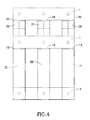
- the exemplary three phase reactor constructed in accordance with principles of the instant invention has a winding ( 4 ) with terminals ( 7 , 8 ); a winding ( 5 ) with terminals ( 9 , 10 ); and a winding ( 6 ) with terminals ( 11 , 12 ).
- FIG. 2 showing an exemplary three phase reactor constructed in accordance with principles of the instant invention.
- FIG. 3 shows an exemplary partial construction of an exemplary three phase reactor constructed in accordance with principles of the instant invention.
- the exemplary three phase reactor has a winding ( 4 ) with terminals ( 7 , 8 ) and a winding ( 5 ) with terminals ( 9 , 10 ) and a winding ( 6 ) with terminals ( 11 , 12 ).
- the exemplary core structure has six vertical non-magnetic straps ( 22 , 24 , 25 , 23 , 26 , and 27 ). As shown in FIGS.
- a space between laminations there can be at least 2 blocks of the instant invention placed between the laminations. In some embodiments, depending on the size, shape, and a space between laminations, there can be at least 5 blocks of the instant invention placed between the laminations. In some embodiments, depending on the size, shape, and a space between laminations, there can be at least 10 blocks of the instant invention placed between the laminations. In some embodiments, depending on the size, shape, and a space between laminations, there can be at least 20 blocks of the instant invention placed between the laminations.
- core(s) of the integrated three phase reactors in accordance with principles of the instant invention can have sufficient performance, when, for example but not limited to, are used in filters that operate in frequency ranges from 2 to 16 kHz. In some embodiments, core(s) of the integrated three phase reactors in accordance with principles of the instant invention sufficiently reduce(s) the fringing fields along the core legs, minimizing or preventing any appreciable (e.g., measurable) amount of winding ( 4 , 5 , 6 ) heating due to the gaps. In some embodiments, the high permeability of the laminations ( 1 , 2 ) can balance the inductances of each of the phases.
- high permeability means a magnetic permeability that is at least 1000 times greater than the permeability of air
- low permeability means a magnetic permeability that is less than 100 times the permeability of air
- core(s) of the integrated three phase reactors in accordance with principles of the instant invention can be implemented consistent with the U.S. Pat. No. 7,142,081 to Shudarek.
- bridges are laminations 1 , 2 , 3 and at least three of the legs 36 , 32 , 31 are constructed from sendust low permeability material.
- the legs 37 , 38 , 39 are constructed from laminations.
- gaps 13 , 14 , 15 , 33 , 34 , 35 ) have nonmagnetic material.
- core(s) of the integrated three phase reactors in accordance with principles of the instant invention can be used with multiple windings consistent with U.S. Pat. No. 7,378,754 to Shudarek, enclosed hereinto and hereby incorporated by references for such purposes.
- core(s) of the integrated three phase reactors in accordance with principles of the instant invention can be used with multiple windings consistent with US Patent Application Pub. No. 20140300433, DRIVE OUTPUT HARMONIC MITIGATION DEVICES AND METHODS OF USE THEREOF, enclosed hereinto and hereby incorporated by references for such purposes.
- an exemplary inventive device of the instant invention is a reactor which includes at least the following: at least one core, including: at least one leg, including: at least one first lamination, where the at least one first lamination is made from at least one first high permeability material, where the at least one first high permeability material has a magnetic permeability that is at least 1000 times greater than the permeability of air; at least one second lamination, where the at least one second lamination is made from at least one second high permeability material, where the at least one second high permeability material has the magnetic permeability that is at least 1000 times greater than the permeability of air; at least one bracket, where the at least one bracket is configured to secure the at least one first lamination and the at least one second lamination in a spatial arrangement to have a space between each other; and a plurality of blocks made from at least one low permeability material, where the at least one low permeability material has the magnetic permeability that is less than 100 times the permeability of air.
- the at least one first high permeability material and the at least one second high permeability material are made from the same magnetic silicon steel material.
- the reactor further includes at least one nonmagnetic insulation positioned in at least one gap between: i) at least two blocks of the plurality of blocks, or ii) at least one block and one of the at least one first lamination and the at least one second lamination.
- each of the plurality of blocks is made from at least one material, selected from the group, consisting of: i) sendust material, ii) molypermalloy material, iii) FluxsanTM material, iv) Hi-FluxTM material, and v) OptilloyTM material.
- the plurality of blocks are configured to be vary in at least one spatial characteristic, where the at least one spatial characteristic is one of: i) a shape, and ii) a size.
- the plurality of blocks include: at least one first block, and at least one second block where the at least one first block and the at least one second block are configured to: i) differ in the at least one spatial characteristic, and ii) fit with each other in the space between the at least one first lamination and the at least one second lamination.
- the plurality of blocks are configured to fit with each other in the space between the at least one first lamination and the at least one second lamination so that at least one gap is absent. In some embodiments, the plurality of blocks are configured to fit with each other in the space between the at least one first lamination and the at least one second lamination to result in at least one gap fittable to be filled with at least one nonmagnetic insulation.
- the reactor is a three phase reactor, and the at least one core further includes: at least one first leg, configured as the at least one leg; at least one second leg, configured as the at least one leg; and at least one third leg, configured as the at least one leg.
Landscapes
- Engineering & Computer Science (AREA)
- Power Engineering (AREA)
- Soft Magnetic Materials (AREA)
Abstract
Description
Claims (9)
Priority Applications (1)
| Application Number | Priority Date | Filing Date | Title |
|---|---|---|---|
| US14/942,556 US9548154B2 (en) | 2014-11-14 | 2015-11-16 | Integrated reactors with high frequency optimized hybrid core constructions and methods of manufacture and use thereof |
Applications Claiming Priority (2)
| Application Number | Priority Date | Filing Date | Title |
|---|---|---|---|
| US201462080054P | 2014-11-14 | 2014-11-14 | |
| US14/942,556 US9548154B2 (en) | 2014-11-14 | 2015-11-16 | Integrated reactors with high frequency optimized hybrid core constructions and methods of manufacture and use thereof |
Publications (2)
| Publication Number | Publication Date |
|---|---|
| US20160148746A1 US20160148746A1 (en) | 2016-05-26 |
| US9548154B2 true US9548154B2 (en) | 2017-01-17 |
Family
ID=55955270
Family Applications (1)
| Application Number | Title | Priority Date | Filing Date |
|---|---|---|---|
| US14/942,556 Active US9548154B2 (en) | 2014-11-14 | 2015-11-16 | Integrated reactors with high frequency optimized hybrid core constructions and methods of manufacture and use thereof |
Country Status (2)
| Country | Link |
|---|---|
| US (1) | US9548154B2 (en) |
| WO (1) | WO2016077831A2 (en) |
Families Citing this family (3)
| Publication number | Priority date | Publication date | Assignee | Title |
|---|---|---|---|---|
| KR102318230B1 (en) * | 2014-12-11 | 2021-10-27 | 엘지이노텍 주식회사 | Inductor |
| CN109411223B (en) * | 2018-11-15 | 2021-01-05 | 宁夏银利电气股份有限公司 | How to make a high frequency transformer |
| CN112635168A (en) * | 2020-12-31 | 2021-04-09 | 上海意兰可电力电子设备有限公司 | Soft characteristic reactor |
Citations (8)
| Publication number | Priority date | Publication date | Assignee | Title |
|---|---|---|---|---|
| US3659191A (en) * | 1971-04-23 | 1972-04-25 | Westinghouse Electric Corp | Regulating transformer with non-saturating input and output regions |
| US5371486A (en) * | 1990-09-07 | 1994-12-06 | Kabushiki Kaisha Toshiba | Transformer core |
| US20060250207A1 (en) * | 2005-05-03 | 2006-11-09 | Mte Corporation | Multiple three-phase inductor with a common core |
| US20100171580A1 (en) | 2007-01-15 | 2010-07-08 | Toru Abe | Reactor core and reactor |
| US7978044B2 (en) * | 2009-01-09 | 2011-07-12 | Hitachi Industrial Equipment Systems Co., Ltd. | Transformer |
| US20110234360A1 (en) | 2008-09-03 | 2011-09-29 | Kenji Nakanoue | Wound iron core for static apparatus, amorphous transformer and coil winding frame for transformer |
| US20120256719A1 (en) | 2011-01-24 | 2012-10-11 | Mte Corporation | Harmonic mitigation devices and applications thereof |
| US20120326822A1 (en) | 2010-05-25 | 2012-12-27 | Toyota Jidosha Kabushiki Kaisha | Reactor |
-
2015
- 2015-11-16 WO PCT/US2015/060914 patent/WO2016077831A2/en not_active Ceased
- 2015-11-16 US US14/942,556 patent/US9548154B2/en active Active
Patent Citations (9)
| Publication number | Priority date | Publication date | Assignee | Title |
|---|---|---|---|---|
| US3659191A (en) * | 1971-04-23 | 1972-04-25 | Westinghouse Electric Corp | Regulating transformer with non-saturating input and output regions |
| US5371486A (en) * | 1990-09-07 | 1994-12-06 | Kabushiki Kaisha Toshiba | Transformer core |
| US20060250207A1 (en) * | 2005-05-03 | 2006-11-09 | Mte Corporation | Multiple three-phase inductor with a common core |
| US20100171580A1 (en) | 2007-01-15 | 2010-07-08 | Toru Abe | Reactor core and reactor |
| US20110234360A1 (en) | 2008-09-03 | 2011-09-29 | Kenji Nakanoue | Wound iron core for static apparatus, amorphous transformer and coil winding frame for transformer |
| US7978044B2 (en) * | 2009-01-09 | 2011-07-12 | Hitachi Industrial Equipment Systems Co., Ltd. | Transformer |
| US20120326822A1 (en) | 2010-05-25 | 2012-12-27 | Toyota Jidosha Kabushiki Kaisha | Reactor |
| US20120256719A1 (en) | 2011-01-24 | 2012-10-11 | Mte Corporation | Harmonic mitigation devices and applications thereof |
| US8692644B2 (en) * | 2011-01-24 | 2014-04-08 | Mte Corporation | Harmonic mitigation devices and applications thereof |
Non-Patent Citations (1)
| Title |
|---|
| International Search Report and Written Opinion from International Application No. PCT/US2015/060914 dated Jan. 27, 2016. |
Also Published As
| Publication number | Publication date |
|---|---|
| WO2016077831A2 (en) | 2016-05-19 |
| US20160148746A1 (en) | 2016-05-26 |
| WO2016077831A3 (en) | 2016-08-11 |
Similar Documents
| Publication | Publication Date | Title |
|---|---|---|
| US11587726B2 (en) | Coupled inductor structure | |
| JP5689338B2 (en) | Reactor device and power conversion device using the reactor device | |
| US8692644B2 (en) | Harmonic mitigation devices and applications thereof | |
| CN105895328B (en) | Three-phase five-limb iron core and stationary electromagnetic equipment | |
| US9667062B2 (en) | Fault current limiter | |
| AU2012209150A1 (en) | Harmonic mitigation devices and applications thereof | |
| CN110832607B (en) | memory choke | |
| US9548154B2 (en) | Integrated reactors with high frequency optimized hybrid core constructions and methods of manufacture and use thereof | |
| CN106057395A (en) | Permanent magnet biased magnetic element assembly and method for implementing same | |
| US9123461B2 (en) | Reconfiguring tape wound cores for inductors | |
| JP2011159851A (en) | Reactor | |
| US20170323717A1 (en) | Gapless core reactor | |
| Aguilar et al. | Method for introducing bias magnetization in ungaped cores:“The Saturation-Gap” | |
| KR101201291B1 (en) | Transformer with backward double winding coil transformer for protceting electro-static shield, surge and eletromagnetic noise | |
| JP2004288882A (en) | Noise filter | |
| CN205943635U (en) | Magnetic element assembly with permanent magnetism bias magnetic | |
| US10325712B2 (en) | Adjustable integrated combined common mode and differential mode three phase inductors with increased common mode inductance and methods of manufacture and use thereof | |
| Jeong et al. | Comparison of iron loss at different manufacturing process of actual stator core | |
| Balehosur et al. | Packet-to-packet variation of flux density in a three-phase, three-limb power transformer core | |
| CN108231366A (en) | Three-phase high frequency transformer | |
| CN104021919A (en) | Blocky combined magnetic core for filter inductor | |
| CN204441077U (en) | A kind of winding construction adopting single magnetic core to realize multiple independent magnetic cell | |
| CA3021004C (en) | Adjustable integrated combined common mode and differential mode three phase inductors with increased common mode inductance and methods of manufacture and use thereof | |
| Yuan et al. | A novel topology of hybrid saturated core fault current limiter considering permanent magnets stability performance | |
| CN102737823A (en) | transformer |
Legal Events
| Date | Code | Title | Description |
|---|---|---|---|
| AS | Assignment |
Owner name: MTE CORPORATION, WISCONSIN Free format text: ASSIGNMENT OF ASSIGNORS INTEREST;ASSIGNOR:SHUDAREK, TODD;REEL/FRAME:039336/0806 Effective date: 20160708 |
|
| STCF | Information on status: patent grant |
Free format text: PATENTED CASE |
|
| AS | Assignment |
Owner name: PNC BANK, NATIONAL ASSOCIATION, PENNSYLVANIA Free format text: SECURITY INTEREST;ASSIGNORS:BLACK HAWK ENERGY SERVICES LTD.;HANDY & HARMAN;HANDYTUBE CORPORATION;AND OTHERS;REEL/FRAME:044678/0939 Effective date: 20171114 |
|
| MAFP | Maintenance fee payment |
Free format text: PAYMENT OF MAINTENANCE FEE, 4TH YEAR, LARGE ENTITY (ORIGINAL EVENT CODE: M1551); ENTITY STATUS OF PATENT OWNER: LARGE ENTITY Year of fee payment: 4 |
|
| MAFP | Maintenance fee payment |
Free format text: PAYMENT OF MAINTENANCE FEE, 8TH YEAR, LARGE ENTITY (ORIGINAL EVENT CODE: M1552); ENTITY STATUS OF PATENT OWNER: LARGE ENTITY Year of fee payment: 8 |
|
| AS | Assignment |
Owner name: MTE, LLC, WISCONSIN Free format text: CONVERSION;ASSIGNOR:MTE CORPORATION;REEL/FRAME:071270/0959 Effective date: 20250430 |
|
| AS | Assignment |
Owner name: MTE, LLC, NEW YORK Free format text: CHANGE OF NAME;ASSIGNOR:MTE CORPORATION;REEL/FRAME:072039/0477 Effective date: 20250430 |